Table of Contents
Advertisement
Quick Links
Advertisement
Table of Contents

Related Manuals for Ekra E1

Summary of Contents for Ekra E1
- Page 1 E1 Semi-automatic screen printer System Manual 30.8.02...
- Page 2 EKRA Eduard Kraft GmbH Maschinenfabrik Zeppelinstrasse 16 D-74357 Bönnigheim Subject to change without notice - No part of this manual may be reproduced, duplicated or translated. In this manual, usually no mention is made of any existing patents, utility model rights or trademark rights applicable to any products.
- Page 3 Screen Printing Machines and Printer Lines of the following models: Microtronic II, Microtronic III, Microtronic IV, Microtronic V, Microtronic VI, Microtronic VII,M8 Mat-S15, Mat-S20, Mat-S30, Mat-S40, Mat-S45, Mat-S50, Mat-S55, E1, E3XL, E4, E5 Series, X5 Series, High Speed Printer, Microtronic III Line, Varistor Printing Line, Glass Printing Machine...
-
Page 4: Table Of Contents
Cleaning the machine and disposal ..............1-14 First aid ......................1-14 2 Safety / Hazards ................2-1 Safety precautions .....................2-1 Safety devices ....................2-2 Emergency-stop switch ..................2-2 Cover......................2-3 Cleaning flap ....................2-3 EKRA / Doku Eisermann E1_020101_E_PDFIVZ.fm E1 Semi-automatic screen printer 30.8.02 System Manual... - Page 5 Setting the pneumatics ..................5-1 Presetting....................5-1 Aligning the PCB....................5-2 Aligning a stencil ....................5-3 Setting up the printing program..............5-4 Setting the down stop..................5-5 Adjusting the printing table................5-7 Printing modes ....................5-8 EKRA / Doku Eisermann E1_020101_E_PDFIVZ.fm E1 Semi-automatic screen printer 30.8.02 System Manual...
- Page 6 Pneumatic parts list ...................8-9 Electric parts list .....................8-10 Electric partslist ....................8-11 Electric drawings .....................8-11 9 Maintenance .................. 9-1 General ......................9-1 Cleaning the machine ..................9-2 Squeegee unit....................9-2 Printing table ....................9-2 EKRA / Doku Eisermann E1_020101_E_PDFIVZ.fm E1 Semi-automatic screen printer 30.8.02 System Manual...
- Page 7 Pneumatic service unit...................9-3 Casing......................9-3 PC positioning system MOPS ................9-4 Bearings and guideways ................9-4 10 Vendor Documentation ............. 10-1 Ordering spare parts ..................10-1 Vendor documentation ..................10-2 Declaration of Trained Personnel EKRA / Doku Eisermann E1_020101_E_PDFIVZ.fm E1 Semi-automatic screen printer 30.8.02 System Manual...
-
Page 8: Introduction
Safety and accident prevention All E1 printers incorporate the very latest technology and are totally reli- able. Nevertheless, a number of rules which will protect the machine and reduce the risk of injury must be observed. -
Page 9: Structure Of The User's Manual
Chapter 4 Switching On and Off explains how to switch on / switch off and start the printer. Chapter 5 Operation explains the procedures used for operating the E1 semi-automatic printer. Chapter 6 Manual Optical Positioning System explains the way the MOPS works and how to use it. -
Page 10: Symbols
You will see this term used in some chapters. Notation CAPITALS indicate commands, instructions/functions and button/key label- ling. Italics are used for the requirements necessary for an action. EKRA / Doku Eisermann 01_EINFUEHRUNG_PDF.FM E1 Semi-automatic screen printer 30.8.02 System Manual... -
Page 11: Taking Delivery Of The Machine
Personnel must not stand under suspended loads. The lifting fork of the fork-lift truck or the platform of the low-lift platform truck must be positioned centrally under the bearing frame construction of the printer. EKRA / Doku Eisermann 01_EINFUEHRUNG_PDF.FM E1 Semi-automatic screen printer 30.8.02 System Manual... -
Page 12: Commissioning
EKRA. EKRA must be notified of any repair work carried out by the owner during the warranty period. If problems or faults occur which you cannot rectify yourself and which are not described in this user’s manual, please contact the EKRA Service Hot-... -
Page 13: Basic Safety Instructions
• to read the chapter on safety and the warnings in this user’s manual and to verify that they have understood their content by signing the last page. EKRA / Doku Eisermann 01_EINFUEHRUNG_PDF.FM E1 Semi-automatic screen printer 30.8.02 System Manual... -
Page 14: Possible Hazards When Operating The Machine
Faults, which may have a detrimental effect on safety, must be rectified immediately. Proper use The E1 semi-automatic printer is intended for printing printable SMT mate- rials (solder paste, SMD adhesive). The machine can also be used for printing hybrid and solar cell media. -
Page 15: Warranty And Liability
Only EKRA Eduard Kraft GmbH is permitted to issue promises of warranty. If defects or damage are repaired by the customer or by a third party with- out the prior agreement of EKRA Eduard Kraft GmbH, the latter shall refuse all liability for consequential damage and cannot acknowledge any further warranty claims. -
Page 16: Safety Regulations
Organisational measures All fitted safety devices must be inspected regularly. Safety devices The E1 semi-automatic printer is equipped with the following safety devices: Emergency-stop switches Emergency-stop switches interrupt the supply of power to the printer. An emergency-stop switch is fitted. -
Page 17: Using Safety Devices
Caution: The operator must not disable any of the safety devices. The printer must never be operated without the enclosures. 1-10 EKRA / Doku Eisermann 01_EINFUEHRUNG_PDF.FM E1 Semi-automatic screen printer 30.8.02 System Manual... -
Page 18: Bypassing The Locks
Checking safety devices • Cover Start the machine while the cover is open. ⇒ The E1 printer should not start. Open the cover during a printing cycle. ⇒ An emergency stop must be triggered. • Cleaning flap Start the machine while the cleaning flap is open. -
Page 19: Informal Safety Measures
• The machine must be inspected for visible damage and checked to ensure that its safety devices are functioning correctly at least once per shift. 1-12 EKRA / Doku Eisermann 01_EINFUEHRUNG_PDF.FM E1 Semi-automatic screen printer 30.8.02 System Manual... -
Page 20: Electrical Hazards
Check loosened screw connections to ensure that they are secure. • Once the maintenance work has been completed, check to ensure that the safety devices are fitted and are functioning correctly. 1-13 EKRA / Doku Eisermann 01_EINFUEHRUNG_PDF.FM E1 Semi-automatic screen printer 30.8.02 System Manual... -
Page 21: Structural Modifications To The Machine
• If pastes or adhesives containing solvents are used, the owner of the E1 printer must ensure that sufficient ventilation is provided. Further- more, the concentration of vapours containing solvents must be contin- ually monitored in order to avoid situations which are detrimental to the health of personnel. -
Page 22: Safety / Hazards
E1 semi-automatic printer. Caution: Always switch off the power supply at the main switch of the E1 printer before starting repair or maintenance work on the machine. The printer must not be operated if the safety devices are not func- tioning correctly. -
Page 23: Safety Devices
Main switch Fig. 1. Safety devices Emergency-stop switch An emergency-stop switch is fitted on the front left-hand side of the E1 semi-automatic printer. Pressing the emergency-stop switch interrupts the supply of power. The emergency-stop switch should only be pressed in emergencies. The emergency-stop switch must be released before the machine is restarted. -
Page 24: Cover
Checking safety devices • Cover Start the machine while the cover is open. ⇒ The E1 printer should not start. Open the cover during a printing cycle. ⇒ An emergency stop must be triggered. • Cleaning flap Start the machine while the cleaning flap is open. -
Page 25: Hazards
Failure to do so could result in hand injuries if the operator reaches into the area containing moving parts. Preventive measures: The operator should only reach into the area containing moving parts when the machine is switched off. EKRA / Doku Eisermann 02_SICHERHEIT_PDF.FM E1 Semi-automatic screen printer 30.8.02 System Manual... -
Page 26: Other Hazards
Do not allow vapours to be produced. Do not allow the solder paste to overheat in the machine. Always wash hands before eating, smoking and drinking. Do not allow solder paste to come into contact with skin. Change contami- nated clothing. EKRA / Doku Eisermann 02_SICHERHEIT_PDF.FM E1 Semi-automatic screen printer 30.8.02 System Manual... -
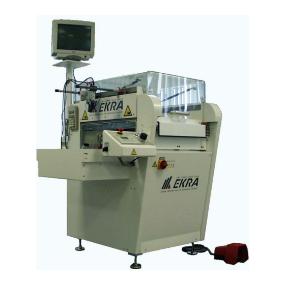
Page 27: Description Of The Machine
Printing can be performed on flexible or rigid base materials such as glass, ceramics, plastic or metal, with a material thickness of up to 10 mm. The E1 semi-automatic screen printer is operated with the aid of a control panel and other operating elements. -
Page 28: Overview Of The Machine Components
9 Emergency-stop switch hand side 4 Protective cover 10 Control desk 5 Print area 11 Printing table guideway 6 Screen for manual optical positioning sys- 12 Foot switch tem (MOPS) EKRA / Doku Eisermann 03_SYSTEM_PDF.FM E1 Semi-automatic screen printer 30.8.02 System Manual... -
Page 29: Electrical Equipment
This is fixed in place with four screws. PC positioning system MOPS Valve terminal Cable feed-through PC with MOPS image processing Fig. 5. PC positioning system / rear of machine EKRA / Doku Eisermann 03_SYSTEM_PDF.FM E1 Semi-automatic screen printer 30.8.02 System Manual... -
Page 30: Snap-Off Setting
1 mm snap-off Fig. 6. Snap-off setting Pneumatic setting Pressure gauge Pressure gauge main operating pressure screen clamping Pressure gauge film tensioning frame Service unit Fig. 7. Pneumatic control unit EKRA / Doku Eisermann 03_SYSTEM_PDF.FM E1 Semi-automatic screen printer 30.8.02 System Manual... -
Page 31: Print Area, With Cover Open
Once the screen fits perfectly in the guideways, lock all levers. To clamp , actuate the screen clamping switch. The clamping cylinders are behind pressurised and clamp the screen in place. Note: Always align the screen layout centrally. EKRA / Doku Eisermann 03_SYSTEM_PDF.FM E1 Semi-automatic screen printer 30.8.02 System Manual... -
Page 32: Printing Table
6 MOPS operating keypad On the E1, the printing screen is fixed and the print material (substrate etc.) is aligned with the screen. To do this, place the test print film in the machine and perform a printing cycle. Then align the PCB with the printed image on the film by adjusting the printing table manually. -
Page 33: Squeegee Unit
To allow cleaning of the screen the cleaning flap can be opened forwards, enabling the underside of the screen to be cleaned. Note: If the screen is removed for cleaning, a new alignment procedure is required. EKRA / Doku Eisermann 03_SYSTEM_PDF.FM E1 Semi-automatic screen printer 30.8.02 System Manual... -
Page 34: Control Desk
The PCB clamping is released automatically. "I": Set the switch to the "I" position to switch on screen clamping manu- ally, and to the "0" position to switch it off again. EKRA / Doku Eisermann 03_SYSTEM_PDF.FM E1 Semi-automatic screen printer 30.8.02... -
Page 35: Functional Description Of The Operating Elements
Up: press this button to move up through the main menu on the display. Down: press this button to move down through the main menu on the display. EKRA / Doku Eisermann 03_SYSTEM_PDF.FM E1 Semi-automatic screen printer 30.8.02 System Manual... -
Page 36: Main Menu Display
Help function. The ON and OFF buttons for switching the control voltage on and off are always active. 3-10 EKRA / Doku Eisermann 03_SYSTEM_PDF.FM E1 Semi-automatic screen printer 30.8.02 System Manual... -
Page 37: Cursor Keys
Enter key: confirm your selection by pressing this key. After you have entered values, they are accepted by the system when you confirm entry with this key. 3-11 EKRA / Doku Eisermann 03_SYSTEM_PDF.FM E1 Semi-automatic screen printer 30.8.02 System Manual... -
Page 38: Technical Data
3a Print - Print (both squeegees unpressurised in parking position) 4 Print 4a Print (both squeegees unpressurised in parking position) Manual optical positioning system (MOPS - option) Cameras 2 manually adjustable CCD cameras 3-12 EKRA / Doku Eisermann 03_SYSTEM_PDF.FM E1 Semi-automatic screen printer 30.8.02 System Manual... - Page 39 1270 mm x 1100 mm x 1420 Working height 850 mm ± 25 mm (adjustable) Weight 350 kg Permissible operating +10°C - +40°C temperature Relative air humidity 30 - 90% 3-13 EKRA / Doku Eisermann 03_SYSTEM_PDF.FM E1 Semi-automatic screen printer 30.8.02 System Manual...
-
Page 40: Switching On And Off
"ON" position. ⇒ Electricity is supplied to the machine. ⇒ The display lights up. ⇒ The following message appears: EKRA E1 CV 2.1 Software version Start reference drive Press the ON button ⇒ The OK and RUN LEDs light up (green). -
Page 41: Switching Off
⇒ The screen printer performs a reference drive. Note: If the cover is opened during the printing process without the Stop button having been pressed first, an emergency stop is triggered. EKRA / Doku Eisermann 04_EIN_AUS_PDF.FM E1 Semi-automatic screen printer 30.8.02 System Manual... -
Page 42: Operation
Do not set the screen clamping to a higher figure than 4 bar. Otherwise the clamping cylinders may be severely damaged. Danger: Do not reach into the printer in the vicinity of the moving printing table. EKRA / Doku Eisermann 05_BEDIEN_PDF.FM E1 Semi-automatic screen printer 30.8.02 System Manual... -
Page 43: Aligning The Pcb
After this, press the ON button and press the foot switch again. The printer performs a reference drive. EKRA / Doku Eisermann 05_BEDIEN_PDF.FM E1 Semi-automatic screen printer 30.8.02 System Manual... -
Page 44: Aligning A Stencil
Close the cover. Press the Stop button again to end the printing process. STOP The printing cycle is brought to an end and the printing table moves out. EKRA / Doku Eisermann 05_BEDIEN_PDF.FM E1 Semi-automatic screen printer 30.8.02 System Manual... -
Page 45: Setting Up The Printing Program
Press either of these two keys until the front squeegee position is set in mm (0 - 550 mm). Confirm entry of the parameter by pressing ENTER EKRA / Doku Eisermann 05_BEDIEN_PDF.FM E1 Semi-automatic screen printer 30.8.02 System Manual... -
Page 46: Setting The Down Stop
(squeegees are lifted out). Close the cover. Press the key and select the PRINTING MODE parameter. Press either of these two keys until printing mode 3 is selected. EKRA / Doku Eisermann 05_BEDIEN_PDF.FM E1 Semi-automatic screen printer 30.8.02 System Manual... - Page 47 Turn the micrometer another 1 to 2 revolutions (2 revolutions = 1mm adjustment distance), depending on the squeegee type (lowering the squeegee). Close the cover. Press the Stop button again. ⇒ The printing cycle is ended STOP EKRA / Doku Eisermann 05_BEDIEN_PDF.FM E1 Semi-automatic screen printer 30.8.02 System Manual...
-
Page 48: Adjusting The Printing Table
Refer to the section on using the manual optical positioning system in this manual. Remove the test print film from the printing table and start the printing process. EKRA / Doku Eisermann 05_BEDIEN_PDF.FM E1 Semi-automatic screen printer 30.8.02 System Manual... -
Page 49: Printing Modes
The forward print- ing process is carried out. After this, the rear squeegee is raised and the front squeegee is lowered. The squeegee unit moves to the rear and a EKRA / Doku Eisermann 05_BEDIEN_PDF.FM E1 Semi-automatic screen printer 30.8.02... -
Page 50: Stencil Printing Mode 3A
A rearward printing process is carried out. A forward printing process then starts again, etc. This procedure continues until the button is pressed. EKRA / Doku Eisermann 05_BEDIEN_PDF.FM E1 Semi-automatic screen printer 30.8.02 System Manual... -
Page 51: Saving A File
Repeat this entry procedure for each character of the file name. When entry of the file name is complete, press the Enter key ⇒ The file name is saved and the main menu appears. 5-10 EKRA / Doku Eisermann 05_BEDIEN_PDF.FM E1 Semi-automatic screen printer 30.8.02 System Manual... -
Page 52: Loading A File
Press either of these two keys until the DELETE FILE function is selected. Confirm selection of the function by pressing ENTER ⇒ The list of file names appears. 5-11 EKRA / Doku Eisermann 05_BEDIEN_PDF.FM E1 Semi-automatic screen printer 30.8.02 System Manual... - Page 53 Chapter 5 Operation Press either of these two keys until the required file is selected. Confirm selection of the file by pressing ENTER ⇒ The file is deleted. 5-12 EKRA / Doku Eisermann 05_BEDIEN_PDF.FM E1 Semi-automatic screen printer 30.8.02 System Manual...
-
Page 54: Manual Optical Positioning System
Chapter 6 Manual Optical Positioning System Manual Optical Positioning System EKRA / Doku Eisermann 06_MOPS_PDF.FM E1 Semi-automatic screen printer 30.8.02 System Manual... -
Page 73: Drawings And Mechanical Parts Lists
Polycarbonate cover (clear, antistatic) 2208000016 MOPS (Manual Optical Positioning System) 2250000006 Universal printing nest E1 350 mm 76012F 2283000010 Universal printing nest E1 450 mm (standard) 73632F 2283000012 Universal printing nest E1 550 mm 73726F 2283000011 Vacuum suction with PICOLINO VTE 6 pump... - Page 75 Parts List 2223000003 Table lifting drive E1 Date of 23.03.2001 Date of change: 20.04.2001 Drawing 77657F design: Variation: Item Var. Quant. Designation Dimension Article 1,00 plate 15*220*500 4052000061 piece 4,00 plate 50*12*164 4052000062 piece 2,00 shaft 30h6*310 4036000006 piece 2,00...
- Page 76 Parts List 2223000003 Table lifting drive E1 Date of 23.03.2001 Date of change: 20.04.2001 Drawing 77657F design: Variation: Item Var. Quant. Designation Dimension Article 1,00 bearing 40*40*45 4057000005 piece 1,00 ledger 24*20*44 4053000060 piece 1,00 angle L30*20*3*14 4056000045 piece 1,00...
- Page 77 Parts List 2223000003 Table lifting drive E1 Date of 23.03.2001 Date of change: 20.04.2001 Drawing 77657F design: Variation: Item Var. Quant. Designation Dimension Article 2,00 pressure piece 10*12 4039000005 piece 2,00 ledger 80*12*80 4053000061 piece 1,00 support 15*8*100 4054000030 piece...
- Page 78 Parts List 2223000003 Table lifting drive E1 Date of 23.03.2001 Date of change: 20.04.2001 Drawing 77657F design: Variation: Item Var. Quant. Designation Dimension Article 4,00 housing unit DW=30 5013080002 piece 2,00 high-performance-joint head DIN ISO 5013120001 piece 12240-4 D=10 right-hand thread...
- Page 80 Parts List 2230000003 Printing table E1 Date of 27.03.2001 Date of change: 11.09.2001 Drawing 77735E design: Variation: Item Var. Quant. Designation Dimension Article 3,00 handle 35*35 4039000006 piece 3,00 flange 65*45 4039000007 piece 2,00 adjustable spindle left-hand thread M16*1*75 4033000010...
- Page 81 Parts List 2230000003 Printing table E1 Date of 27.03.2001 Date of change: 11.09.2001 Drawing 77735E design: Variation: Item Var. Quant. Designation Dimension Article 1,00 bolt 12h6*38 4034000008 piece 1,00 angle L20*20*3*44 4056000055 piece 600,00 energy chain series 06 E2 B=16.5 R=28...
- Page 83 Parts List 2213000003 Screen clamping E1 Date of 28.03.2001 Date of change: 12.09.2001 Drawing 77859E design: Variation: Item Var. Quant. Designation Dimension Article 2,00 angle L50*45*10*170 4056000056 piece 4,00 cylinder holder 50*20*80 4052000085 piece 2,00 angle L50*50*5.5*60 4056000057 piece 2,00...
- Page 85 Parts List 2210000003 Upper part E1 Date of 18.04.2001 Date of change: 18.04.2001 Drawing 77843F design: Variation: Item Var. Quant. Designation Dimension Article 2,00 angle L60*60*6*875 4056000063 piece 2,00 bearing block 4057000006 piece 2,00 instep block 12*10*40 4053000030 piece 2,00...
- Page 86 Parts List 2210000003 Upper part E1 Date of 18.04.2001 Date of change: 18.04.2001 Drawing 77843F design: Variation: Item Var. Quant. Designation Dimension Article 2,00 housing unit DW=20 5013080001 piece 4,00 shaft bracket 1055 für shaft d=16 5031180001 piece 2,00 shaft...
- Page 88 Parts List 2216000001 Squeegee device E1 stroke 60 Date of 19.04.2001 Date of change: 16.05.2001 Drawing 77844E design: Variation: Item Var. Quant. Designation Dimension Article 2,00 angle 52*52*166 4053000083 piece 1,00 plate 100*6*160 4052000097 piece 2,00 stud bolt 12*50 4034000011...
- Page 89 Parts List 2216000001 Squeegee device E1 stroke 60 Date of 19.04.2001 Date of change: 16.05.2001 Drawing 77844E design: Variation: Item Var. Quant. Designation Dimension Article 4,00 knurled head screw DIN 464-M6*18-St- 6*18 5050000051 piece zinced 2,00 DU-bush cylindric 10*12*10 5012070005...
- Page 90 2,00 distance 18*213 4033000014 piece 1,00 distance 18*100 4033000015 piece 1,00 bearing 20*8*33 4057000007 piece 1,00 cover ring E1 4032000005 piece 1,00 panel housing 5392000005 piece 1,00 mounting sheet emtal 2.5*90*280 4040000137 piece 1,00 angle L100*40*5*40 4056000065 piece 1,00...
- Page 91 Parts List 2297000001 Casing E1 Date of 30.03.2001 Date of change: 05.12.2001 Drawing 77325 design: Variation: Item Var. Quant. Designation Dimension Article 1,00 Rollo-cover 5900000013 piece 2,00 sheet metal 1.5*239*989 4040000141 piece 2,00 sheet metal 1.5*99*715 4040000142 piece 2,00 sheet metal 1.5*131*779...
- Page 92 Plexiglass cover Date of 27.06.2001 Date of change: 14.11.2001 Drawing 77326 design: Variation: Item Var. Quant. Designation Dimension Article 1,00 cover E1 XT clear 5075000006 piece 1,00 stiffening angle L80*80*6*30 4056000094 piece 1,00 stiffening angle L80*80*6*30 4056000095 piece 2,00 stiffening angle...
- Page 93 Date of 27.06.2001 Date of change: 05.07.2001 Drawing 68027 design: Variation: Item Var. Quant. Designation Dimension Article 1,00 cover E1 PC clear antistatic 5075000007 piece 1,00 stiffening angle L80*80*6*30 4056000094 piece 1,00 stiffening angle L80*80*6*30 4056000095 piece 2,00 stiffening angle...
- Page 94 2,00 angle L50*22*3*100 4056000070 piece 2,00 block 15*15*80 4053000122 piece 2,00 ledger 7.5*30 4035000010 piece 1,00 plate for plug E1 3*74*205 4052000188 piece 1,00 plate 10*162*686 4052000189 piece 1,00 plate 10*60*686 4052000190 piece 1,00 linear guidance Bgr.15 SSR 2 carrier...
- Page 96 4,00 pin ISO 28734-3*8-A-St 5055000005 piece 2,00 spring DIN 2098-1.10*9.20*26.00 5023000011 piece stainless 4,00 Polymer plain bearing 10*12*14.5 5012050001 piece 1,00 tightening unit EV-10/30 stroke 3mm 5027020003 piece 1,00 print plate EV-10/30-DP 5027020004 piece Seite/Page 1 © EKRA 10.04.02...
- Page 98 4,00 pin ISO 28734-3*8-A-St 5055000005 piece 2,00 spring DIN 2098-1.10*9.20*26.00 5023000011 piece stainless 4,00 Polymer plain bearing 10*12*14.5 5012050001 piece 1,00 tightening unit EV-10/30 stroke 3mm 5027020003 piece 1,00 print plate EV-10/30-DP 5027020004 piece Seite/Page 1 © EKRA 10.04.02...
- Page 100 4,00 pin ISO 28734-3*8-A-St 5055000005 piece 2,00 spring DIN 2098-1.10*9.20*26.00 5023000011 piece stainless 4,00 Polymer plain bearing 10*12*14.5 5012050001 piece 1,00 tightening unit EV-10/30 stroke 3mm 5027020003 piece 1,00 print plate EV-10/30-DP 5027020004 piece Seite/Page 1 © EKRA 10.04.02...
- Page 101 Parts List 2283000011 Universal print nest 550mm Date of 27.06.2001 Date of change: 14.09.2001 Drawing 73726F design: Variation: Item Var. Quant. Designation Dimension Article 1,00 table plate 15*440*580 4052000187 piece Seite/Page 2 © EKRA 10.04.02...
- Page 102 Schott-plug in connection di=4 auf di=4, 5673000032 piece thread M10 1,00 sheet metal 2*60*191 4040000233 piece 1,00 3pol. clutch box DIN 43 650 version B 5360000048 piece 1,00 illuminated seal for plug-in connector 5360000049 piece DIN 43 650 Seite/Page 1 © EKRA 10.04.02...
- Page 103 5677000017 piece outside 1,00 threaded elbow joint 90° di=10, R3/8 5677000018 piece outside 1,00 3pol. clutch box DIN 43 650 version B 5360000048 piece 1,00 illuminated seal for plug-in connector 5360000049 piece DIN 43 650 Seite/Page 1 © EKRA 10.04.02...
- Page 105 1*467*580 4040000128 piece 1,00 foil 520*0.5*380 4090000006 piece 2,00 bracket block 20*20*21 4053000072 piece 2,00 bracket block 60*20*78.5 4053000073 piece 2,00 drilling sleeve DIN 179-A 5.1*20 5027010002 piece 2,00 pin ISO 28734-5*40-A-St 5*40 5055000013 piece Seite/Page 1 © EKRA 10.04.02...
- Page 107 20*10*528 4054000140 piece 2,00 angle L30*30*3*737 4056000097 piece 2,00 rectangular tube 30*30*3*737 4010000066 piece 2,00 bracket 20*20*528 4054000141 piece 4,00 distance 20*4*27.5 4052000191 piece 4,00 cover prop for rectangular tube 30*30, 30*30 5900000028 piece black Seite/Page 1 © EKRA 10.04.02...
- Page 110 Parts List 4054000124 Magnet ledge 350 mm Date of 06.09.2001 Date of change: 29.01.2002 Drawing 75545D design: Variation: Item Var. Quant. Designation Dimension Article 1,00 cutting plate AlMgSi1 40*30*353 40*30*353 6361400009 piece Seite/Page 1 © EKRA 10.04.02...
- Page 112 Item Var. Quant. Designation Dimension Article 1,00 magnet strip 24.7*40*450 4054000142 piece 450,00 foil footsure 0.6*400 black (roll 9000mm) 5900000025 500,00 double side scotch tabe PVC 370 8012520004 b=38mm (roll=50m) 5,00 magnet blank Samarium-Cobalt 5900000020 piece Seite/Page 1 © EKRA 10.04.02...
- Page 113 Parts List 2299000011 Magnet pin Date of 25.04.2001 Date of change: 25.04.2001 Drawing 74554B design: Variation: Item Var. Quant. Designation Dimension Article 1,00 16*25,4 4039000013 piece 1,00 magnet round 10*3 5900000014 piece Seite/Page 1 © EKRA 10.04.02...
- Page 114 20,00 push-in fitting straight di=4 thread M5 5673000024 piece 1,00 push-in fitting angle di=6 thread R1/8 5673000033 piece 2,00 plug in connection ramification di=6 of 5673000034 piece di=6 1,00 silencer connection G1/8 outside 5690000012 Seite/Page 1 © EKRA 10.04.02...
- Page 115 5614000001 piece 10,00 screwed sealing plug DIN 908-M5-Al 5677000014 piece with SW7 outside 1,00 3pol. clutch box DIN 43 650 version B 5360000048 piece 1,00 illuminated seal for plug-in connector 5360000049 piece DIN 43 650 Seite/Page 2 © EKRA 10.04.02...
-
Page 116: Electrical And Pneumatic Equipment
Control cabinet X4.1 X2.1 A4.1 X1.0 X2.0 A3.1 Fig. 14. Control cabinet Control desk Emergency stop Squeegee pressure indicator Control panel Pressure reducer squeegee pressure Fig. 15. Control desk EKRA / Doku Eisermann 08_ELEKTRO_PNEU_PDF.FM E1 Semi-automatic screen printer 30.8.02 System Manual... -
Page 117: Snap-Off Control
Chapter 8 Electrical and Pneumatic Equipment Snap-off control S13 S14 M4.1 Fig. 16. Snap-off control Cleaning flap Fig. 17. Cleaning flap EKRA / Doku Eisermann 08_ELEKTRO_PNEU_PDF.FM E1 Semi-automatic screen printer 30.8.02 System Manual... -
Page 118: Snap-Off Control
Chapter 8 Electrical and Pneumatic Equipment Snap-off control S3.1 M4.1 Fig. 18. Snap-off control Cover safety switch Fig. 19. Cover safety switch EKRA / Doku Eisermann 08_ELEKTRO_PNEU_PDF.FM E1 Semi-automatic screen printer 30.8.02 System Manual... - Page 119 Electrical and Pneumatic Equipment Table drive motor, view from rear Fig. 20. Table drive motor, view from rear Table loading position sensors S2.1 Fig. 21. Table loading position sensors EKRA / Doku Eisermann 08_ELEKTRO_PNEU_PDF.FM E1 Semi-automatic screen printer 30.8.02 System Manual...
-
Page 120: Squeegee Position Sensor
Squeegee position sensor Fig. 22. Squeegee position sensor Squeegee motor Fig. 23. Squeegee motor Note: Other electrical components, such as motors and ….., are listed in the mechanical parts lists. EKRA / Doku Eisermann 08_ELEKTRO_PNEU_PDF.FM E1 Semi-automatic screen printer 30.8.02 System Manual... -
Page 121: Pneumatic Equipment
Service unit and pressure adjustment Pressure regulator main pneumatic connection Pressure regulator screen clamping Pressure regulator film tensioning frame Service unit Fig. 25. Service unit and pressure adjustment EKRA / Doku Eisermann 08_ELEKTRO_PNEU_PDF.FM E1 Semi-automatic screen printer 30.8.02 System Manual... -
Page 122: Squeegee Pressure
Chapter 8 Electrical and Pneumatic Equipment Squeegee pressure Squeegee pressure indicator Pressure reducer squeegee pressure Fig. 26. Saueegee pressure Snap-off Fig. 27. Snap-off EKRA / Doku Eisermann 08_ELEKTRO_PNEU_PDF.FM E1 Semi-automatic screen printer 30.8.02 System Manual... -
Page 123: Valve Terminal
Note: In the case of the Picoline VTE6 and VLT15 options and the venturi suction option, the valves are included in the mechanical parts list. EKRA / Doku Eisermann 08_ELEKTRO_PNEU_PDF.FM E1 Semi-automatic screen printer 30.8.02 System Manual... -
Page 124: Pneumatic Parts List
162806 HE-1/8-D-Mini Screen clamping valve SV-3-M5 006817 selector switch N-22 S black 009301 Display squeegee gauge 1/8"NW40/0-4bar 304/40 pressure Y14 Squeegee pres- pressure regulator 0,07-4,0 11-818-100 11-818-100 sure EKRA / Doku Eisermann 08_ELEKTRO_PNEU_PDF.FM E1 Semi-automatic screen printer 30.8.02 System Manual... -
Page 125: Electric Parts List
13.537.12 position limitation switch 1s 1ö 3SE3200-1D position limitation switch 1s 1ö 3SE3200-1D S2 / S2.1 proximity sensorM8x1 NJ1,5-8GM40-E2 15176 S3 / S3.1 proximity sensorM8x1 NJ1,5-8GM40-E2 15176 8-10 EKRA / Doku Eisermann 08_ELEKTRO_PNEU_PDF.FM E1 Semi-automatic screen printer 30.8.02 System Manual... -
Page 126: Electric Drawings
M 4/8 SF 011513106 Electric partslist The electric partlist 2499000127 and 2499000128 are following on the next pages Electric drawings The following pages contain the electric drawings 8-11 EKRA / Doku Eisermann 08_ELEKTRO_PNEU_PDF.FM E1 Semi-automatic screen printer 30.8.02 System Manual... - Page 127 Electrical Parts List 2499000127 Control E1 Date of 01.03.2002 Date of change: 12.04.2002 Circuit E1_006 design: diagram: Article description Order no. Frequency converter 0.9kVA 230V 5382000007 A3.1 Soldering terminal MP12 (12paired transition) 5360000055 A4.1 Overvoltage load module 5382000006 Basic module...
- Page 128 Electrical Parts List 2499000128 Machine E1 Date of 01.03.2002 Date of change: 12.04.2002 Circuit E1_006 design: diagram: Article description Order no. Analogue power controller 5382000005 Encoder 5355000003 for M3 Cable Ölflex-110CY 4G*1.5mm² with shield 5361000092 for M4 Cable Ölflex-110 3G*1.5mm²...
- Page 129 EKRA GmbH Zeppelinstr.16 D-74357 Bönnigheim Tel.: +49 (0) 7143 / 88 44-0 Fax: +49 (0) 7143 / 88 44 22 email: service@EKRA.com Kunde / Customer : Ort / City : Bönnigheim Anlage / System : E1-006 Maschinen-Nr. / Serial number : Auftrags-Nr.
- Page 130 Vakuumpumpe MOPS-B Vacuum pump Zuleitung 240V 50Hz power supply 240V 50Hz Vorsicherung max: 10A pre-fusing max: 10A Anlage Datum 20.09.99 Datum Name E1-006 EKRA GmbH Ersteller Heupel letzte Änderung 17.07.02 Heime Zeppelinstr.16 D-74357 Bönnigheim Blatt-Nr. Gepr. Einspeisung Tel.: +49 (0) 7143 / 88 44-0...
- Page 131 Schuzklappe vorne protection cover front -S04 Schutzhaube Protection cover /4.6 PV+24V /6.1 Anlage Datum 20.09.99 Datum Name E1-006 EKRA GmbH Ersteller Heupel letzte Änderung 16.07.02 Heime Zeppelinstr.16 D-74357 Bönnigheim Blatt-Nr. Gepr. Hauben und Haubenüberbrückung Tel.: +49 (0) 7143 / 88 44-0...
- Page 132 Table up footswitch Not-Aus Tisch ausgefahren Tisch eingefahren Tisch unten Tisch oben Fußtaster Anlage Datum 21.09.99 Datum Name E1-006 EKRA GmbH Ersteller Heupel letzte Änderung 17.07.02 Heime Zeppelinstr.16 D-74357 Bönnigheim Blatt-Nr. Gepr. Eingänge 1-6 Tel.: +49 (0) 7143 / 88 44-0...
- Page 133 /9.6 MOPS Freigabe Haube/Klappe offen Überwach. überwachen R.kopf mitte Hau./Kl. geschlossen Reserve Anlage Datum 21.09.99 Datum Name E1-006 EKRA GmbH Ersteller Heupel letzte Änderung 17.07.02 Heime Zeppelinstr.16 D-74357 Bönnigheim Blatt-Nr. Gepr. Eingänge 7-12 Tel.: +49 (0) 7143 / 88 44-0...
- Page 134 X6:12 /6.1 /4.8 /6.1 /2.5 /7.4 /2.5 /7.3 Anlage Datum 21.09.99 Datum Name E1-006 EKRA GmbH Ersteller Heupel letzte Änderung 17.07.02 Heime Zeppelinstr.16 D-74357 Bönnigheim Blatt-Nr. Gepr. Ausgänge 1-6 Tel.: +49 (0) 7143 / 88 44-0 Norm...
- Page 135 SUCTION AIR X6:12 /5.8 PV+24V PV+24V /2.8 /9.1 /5.8 /7.1 Anlage Datum 21.09.99 Datum Name E1-006 EKRA GmbH Ersteller Heupel letzte Änderung 17.07.02 Heime Zeppelinstr.16 D-74357 Bönnigheim Blatt-Nr. Gepr. Ausgänge 7-12 Tel.: +49 (0) 7143 / 88 44-0 Norm Bl von Anz...
- Page 136 -M4.1 -En4 Trenn.motor Rakelmotor R.Endcoder separate motor Squeegee motor squeegee Encoder Anlage Datum 28.09.99 Datum Name E1-006 EKRA GmbH Ersteller Heupel letzte Änderung 17.07.02 Heime Zeppelinstr.16 D-74357 Bönnigheim Blatt-Nr. Gepr. Rakel und Trenngeschwindigkeit Tel.: +49 (0) 7143 / 88 44-0...
- Page 137 Table motor Freq Motoranschluß U V W U V W PE Tischantrieb Table motor Anlage Datum 11.10.99 Datum Name E1-006 EKRA GmbH Ersteller Heupel letzte Änderung 16.07.02 Heime Zeppelinstr.16 D-74357 Bönnigheim Blatt-Nr. Gepr. Tischantrieb Tel.: +49 (0) 7143 / 88 44-0...
- Page 138 1N 4007 D11.1 1N 4007 BY 251 Lötsockel BY 251 0,47k 1,8k Anlage Datum 26.02.01 Datum Name E1-006 EKRA GmbH Ersteller Ralf Pfennigwerth letzte Änderung 16.07.02 Heime Zeppelinstr.16 D-74357 Bönnigheim Blatt-Nr. Gepr. Tischantrieb Tel.: +49 (0) 7143 / 88 44-0...
- Page 139 - P.Bus /11.1 X2.1:1 /11.1 X2.1:8 /11.1 Display-I/O Display-I/O Basismodul IM-880 Anlage Datum 12.10.99 Datum Name E1-006 EKRA GmbH Ersteller Heupel letzte Änderung 16.07.02 Heime Zeppelinstr.16 D-74357 Bönnigheim Blatt-Nr. Gepr. Display-I/O Tel.: +49 (0) 7143 / 88 44-0 Norm Bl von Anz...
- Page 140 - P.Bus /10.8 X2.1:1 /10.8 X2.1:8 /10.8 Motorregelung motor control Basismodul IM-880 Anlage Datum 12.10.99 Datum Name E1-006 EKRA GmbH Ersteller Heupel letzte Änderung 16.07.02 Heime Zeppelinstr.16 D-74357 Bönnigheim Blatt-Nr. Gepr. Motorregelung Tel.: +49 (0) 7143 / 88 44-0 Norm...
- Page 141 Rakeldruck squeegee pressure /13.1 Wartungseinheit: 5-6 bar Anlage Datum 18.09.00 Datum Name E1-006 EKRA GmbH Ersteller Thomas Illing letzte Änderung 17.07.02 Heime Zeppelinstr.16 D-74357 Bönnigheim Blatt-Nr. Gepr. Pneumatik / pneumatic Tel.: +49 (0) 7143 / 88 44-0...
- Page 142 PCB-clamping Vakuum Tisch vacuum table Folienspanrahmen Y11.1 screen tension frame /12.8 Anlage Datum 18.09.00 Datum Name E1-006 EKRA GmbH Ersteller Thomas Illing letzte Änderung 17.07.02 Heime Zeppelinstr.16 D-74357 Bönnigheim Blatt-Nr. Gepr. Pneumatik / pneumatic Tel.: +49 (0) 7143 / 88 44-0...
- Page 143 30x60x670 (Kabelkanal) 30x510 (Hutschiene) 30x60x300 (Kabelkanal) 30x60x510 (Kabalkanal) 30x60x100 (Kabalkanal) 30x460 (Hutschiene) 30x60x670 (Kabelkanal) Anlage Datum 21.10.99 Datum Name E1-006 EKRA GmbH Ersteller Heupel letzte Änderung 16.07.02 Heime Zeppelinstr.16 D-74357 Bönnigheim Blatt-Nr. Gepr. Montageplatte Tel.: +49 (0) 7143 / 88 44-0...
- Page 144 Gesperrt A3.1 Anlage Datum 21.10.99 Datum Name E1-006 EKRA GmbH Ersteller Heupel letzte Änderung 17.07.02 Heime Zeppelinstr.16 D-74357 Bönnigheim Blatt-Nr. Gepr. Montageplatte Tel.: +49 (0) 7143 / 88 44-0 Norm Bl von Anz 16/16...
-
Page 145: Maintenance
Caution: Switch off the main switch on the machine before starting mainte- nance work. Switch the E1 printer off at the main switch. Open the cover. Note: Only expert personnel who have received relevant training are permit- ted to carry out maintenance work. -
Page 146: Cleaning The Machine
Always keep the printing table clean in order to ensure that the PCB is positioned perfectly. Clean the clamping strips, PCB supports and the base plate of the printing table. EKRA / Doku Eisermann 09_WARTUNG_PDF.FM E1 Semi-automatic screen printer 30.8.02 System Manual... -
Page 147: Pneumatic Service Unit
Only use antistatic agents for cleaning the cover. Note: Other cleaning agents may cause damage to the covers (cracking). Note: The transport belts and toothed belts do not require maintenance. EKRA / Doku Eisermann 09_WARTUNG_PDF.FM E1 Semi-automatic screen printer 30.8.02 System Manual... -
Page 148: Pc Positioning System Mops
Clean the guideways with a dry, clean cloth. Note: If you intend not to use the E1 printer for a relatively long time, protect the guideways from rust by applying grease (anti-friction bearing grease conforming to DIN 51825, consistency class NLGI 2 or NLGI 3). -
Page 149: 10 Vendor Documentation
Telephone: ++49 (0) 71 43 88 44-0 Facsimile: ++49 (0) 71 43 88 44 22 Sales Dept. Facsimile: ++49 (0) 71 43 88 44 29 Service Dept. 10-1 EKRA / Doku Eisermann 10_ZULIEF_PDF.FM E1 Semi-automatic screen printer 30.8.02 System Manual... -
Page 150: Vendor Documentation
Chapter 10 Vendor Documentation Vendor documentation Manufacturer Designation Item no./ Order no. KEB Antriebstechnik Combivert 00.00EMV- User’s Manual K002 KEB Antriebstechnik Combivert 2 00.F4.SOB- User’s Manual K111 10-2 EKRA / Doku Eisermann 10_ZULIEF_PDF.FM E1 Semi-automatic screen printer 30.8.02 System Manual... -
Page 184: Declaration Of Trained Personnel
Declaration of Trained Personnel I herewith declare that I have attended an internal training course for the operation of the E1 semi-automatic screen printer and have been informed about all details regarding safety. I also declare that I have read and understood this operating manual in full and that I have entirely understood my subject matter.
Need help?
Do you have a question about the E1 and is the answer not in the manual?
Questions and answers