Table of Contents
Advertisement
Quick Links
Table of Contents
2017-11-2310
Operating manual
EC Declaration of Conformity
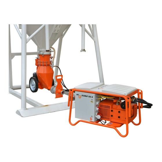
PFT CONVEYING SYSTEM
PFT SILOMAT XXL D RAL2004
Part 2 Overview – Operation - Spare parts lists
Article number of the operating manual: 00629976
Article number of the parts list PFT SILOMAT XXL D 50 Hz RAL2004
Article number of the parts list PFT SILOMAT XXL D 60 Hz RAL2004
Read the operating manual prior to starting any work!
-00606758
-00603707
Advertisement
Table of Contents
Troubleshooting

Related Manuals for Knauf PFT SILOMAT XXL D


Summary of Contents for Knauf PFT SILOMAT XXL D
- Page 1 PFT SILOMAT XXL D RAL2004 Part 2 Overview – Operation - Spare parts lists Article number of the operating manual: 00629976 Article number of the parts list PFT SILOMAT XXL D 50 Hz RAL2004 -00606758 Article number of the parts list PFT SILOMAT XXL D 60 Hz RAL2004 ...
- Page 2 © Knauf PFT GmbH & Co. KG P.O. Box no. 60 97343 Iphofen Einersheimer Straße 53 97346 Iphofen Germany Phone +49 9323 31-760 Fax +49 9323 31-770 Technical hotline +49 9323 31-1818 info@pf.net Internet: www.pft.net...
-
Page 3: Table Of Contents
10 Quality Control sticker ......10 22.1 Main switch ........28 22.2 Conveying process ......28 11 Dimension sheet PFT SILOMAT XXL D ... 11 22.3 Empty alarm of level sensor ....29 12 Assembly and functioning: ....... 12 22.4 Switching off ........30 12.1 Overview of the assembly units .. - Page 4 30.2 Check the slider width ......43 34.15 Carrier cmpl. SILOMAT XXL D ..62 30.3 Setting values of SILOMAT XXL D ..44 34.16 Carrier cmpl. SILOMAT XXL D ..63 34.17 Gear motor SILOMAT XXL D ..... 64 31 Monitor the pressure control ....
-
Page 5: Ec Declaration Of Conformity
(Dipl. in Industrial Engineering, University of Applied Sciences) Michael Duelli, Einersheimer Straße 53, 97346 Iphofen. The technical documentation is available from: Knauf PFT GmbH & Co. KG, Technical Department, Einersheimer Straße 53, 97346 Iphofen. Iphofen, Dr. York Falkenberg Managing director... -
Page 6: Inspection
PFT CONVEYING SYSTEM Part 2 Overview – Operation - Spare parts lists Inspection 3 Inspection 3.1 Inspection by machine operator Prior to each shift, the machine operator has to examine the effectiveness of the control and safety devices, as well as the proper fitting of the protection devices. ... -
Page 7: Division
PFT CONVEYING SYSTEM Part 2 Overview – Operation - Spare parts lists Accessories 4.3 Division The operating manual is divided into 2 books: Part 1 Safety General safety instructions about article number 00132670 Part 2 Overview, operation, service and spare parts lists. (This book) For safe operation of the device, both the parts have to be observed. -
Page 8: Technical Data
SILOMAT XXL D 50 Hz 00 60 67 58 SILOMAT XXL D 60 Hz 00 60 37 07 Weight of the complete conveying Detail Value Unit system SILOMAT XXL D 50 / 60Hz Detail Value Unit Length 1150 Width Height Carrier cmpl. -
Page 9: Connection Values 60 Hz
PFT CONVEYING SYSTEM Part 2 Overview – Operation - Spare parts lists Technical data 6.3 Connection values 60 Hz Electrical details Detail Value Unit Voltage 3Ph./ 50Hz Power consumption approximately 21.7 Power input 10.7 Connection Fuse protection, at least 32A type C Power Unit Designation... -
Page 10: Power Values 60 Hz
PFT CONVEYING SYSTEM Part 2 Overview – Operation - Spare parts lists Sound power level 6.6 Power values 60 Hz Detail Value Unit Pump capacity, approx. at 140m 20 kg/min Feed range in m* 140 Metre Operating pressure, max. 2.5 bar Compressor ventilation system 122 Nm³/h performance... -
Page 11: Dimension Sheet Pft Silomat Xxl D
PFT CONVEYING SYSTEM Part 2 Overview – Operation - Spare parts lists Dimension sheet PFT SILOMAT XXL D 11 Dimension sheet PFT SILOMAT XXL D 1410 1150 Fig. 5: Dimension sheet Page 11 22 April 2020 13:52:52 22 A pril 202 0 13: 52:5 2... -
Page 12: Assembly And Functioning
PFT CONVEYING SYSTEM Part 2 Overview – Operation - Spare parts lists Assembly and functioning: 12 Assembly and functioning: 12.1 Overview of the assembly units Fig. 6: Table of the assembly groups 1. Conveying air - Bypass 11. Squeeze valve 2. -
Page 13: Carrier Silomat Xxl D
PFT CONVEYING SYSTEM Part 2 Overview – Operation - Spare parts lists Assembly and functioning: 12.2 Carrier SILOMAT XXL D Fig. 7: Table of the assembly groups 1. Ventilation of the carrier 9. Power supply from the control box for the gear motor 2. -
Page 14: Xxl D
PFT CONVEYING SYSTEM Part 2 Overview – Operation - Spare parts lists Assembly and functioning: 12.3 Compressor / control box SILOMAT XXL D Fig. 8: Compressor / Control box SILOMAT XXL D 1. Solenoid valve for ventilating the carrier 11. Safety valve 2.2 bar 2. -
Page 15: Xxl D
PFT CONVEYING SYSTEM Part 2 Overview – Operation - Spare parts lists Assembly and functioning: 12.4 Overview of the control box SILOMAT XXL D Fig. 9: Description of the control box 1. Master switch is also emergency-stop switch 6. Power supply from the control box for the gear 2. -
Page 16: Operating Modes
PFT CONVEYING SYSTEM Part 2 Overview – Operation - Spare parts lists Function 12.5 Operating modes The air compressor can be operated in two different operating modes: AUTOMATIC (right) The air compressor operates if the rotary paddle switch requires material. MANUAL (left) The air compressor operates in the continuous mode in the “Hand”... - Page 17 PFT CONVEYING SYSTEM Part 2 Overview – Operation - Spare parts lists Function Conveying cycle: The conveying air is now converted from the bypass air to the conveying air so that the material is fluidised right at the end of the metering worm. The metering worm starts conveying the dry material to the conveyor hose with a delay of 3 seconds.
-
Page 18: Intended Use Air Compressor
PFT CONVEYING SYSTEM Part 2 Overview – Operation - Spare parts lists Intended use air compressor 14 Intended use air compressor 14.1 Intended purpose air compressor The tool is conceptualised and designed exclusively for the purpose of use specified here. Attention! The air compressor is intended exclusively for the generation of compressed air and is to be used with... -
Page 19: General Positioning Of The Air Compressor
PFT CONVEYING SYSTEM Part 2 Overview – Operation - Spare parts lists Intended use air compressor 14.3 General positioning of the air compressor The air compressor complies with the national and international safety regulations and can therefore also be used in damp rooms and/or outdoors. -
Page 20: Transport, Packing And Storage
PFT CONVEYING SYSTEM Part 2 Overview – Operation - Spare parts lists Transport, packing and storage 15 Transport, packing and storage 15.1 Safety instructions for transport Improper transport ATTENTION! Damage from improper transport! Improper transport may cause substantial property damage. Therefore: ... -
Page 21: Transport
PFT CONVEYING SYSTEM Part 2 Overview – Operation - Spare parts lists Transport, packing and storage 15.2 Transport Anchor points Anchor the Silomat system at the marked anchor points (1) for transport by crane. Attachment: 1. Anchor the hooks to the crane hooks accordingly. Fig. -
Page 22: Transport Inspection
PFT CONVEYING SYSTEM Part 2 Overview – Operation - Spare parts lists Transport, packing and storage 15.3 Transport inspection On receipt check the delivery immediately for completeness and transport damage. In case of externally visible transport damage, proceed as follows: ... -
Page 23: Operation
PFT CONVEYING SYSTEM Part 2 Overview – Operation - Spare parts lists Operation 16 Operation 16.1 Safety Personal protective equipment The following protective equipment has to be worn for all operative work: Protective clothing Protective goggles Protective gloves ... -
Page 24: Machine Preparations
PFT CONVEYING SYSTEM Part 2 Overview – Operation - Spare parts lists Machine preparations 17 Machine preparations Prior to operating the machine carry out the following steps for preparing the machine: Warning! SILOMAT systems for free-fall silos may be connected only to depressurised silos / containers. -
Page 25: Prepare The Carrier
PFT CONVEYING SYSTEM Part 2 Overview – Operation - Spare parts lists Prepare the carrier WARNING! Danger to life from rotating parts! Improper operation may lead to serious damage to persons or property. The motor must be operated only with the control cabinet of the machine. -
Page 26: Laying Conveyor Lines
PFT CONVEYING SYSTEM Part 2 Overview – Operation - Spare parts lists Connections 19.3 Laying conveyor lines NOTE! The conveyor line may not be laid level in order to ensure an optimum work flow of the system in case of long conveyor stretches. -
Page 27: Opening The Silo Discharge Flap Valve
PFT CONVEYING SYSTEM Part 2 Overview – Operation - Spare parts lists Opening the silo discharge flap valve 3. Connect the control cable from the CEE - socket outlet (1) to the rotary paddle switch of the injection hood (3). Fig. -
Page 28: Hazardous Dusts
PFT CONVEYING SYSTEM Part 2 Overview – Operation - Spare parts lists Switching on 21.1 Hazardous dusts Warning! In the long term, inhaled dust can lead to lung damage or have other adverse health effects. NOTE! The machine operator or the person working in the dusty area always has to wear a dust protection mask Fig. -
Page 29: Empty Alarm Of Level Sensor
The conveying system is controlled by the material consumption of the cleaning machine. The PFT SILOMAT XXL D can be connected to every free-fall silo and feeds approximately 20 kg of dry mortar per minute to a mixing pump, e.g. PFT G 4, up to 140 m. -
Page 30: Switching Off
PFT CONVEYING SYSTEM Part 2 Overview – Operation - Spare parts lists Shutdown in case of emergency 22.4 Switching off 1. Switch off the system by pressing the red push button control voltage “ON/OFF” (1). 2. Switch the hand - “0” - automatic switch (2) to “0”. 3. -
Page 31: Action In Case Of Power Cut
Fig. 28: Disconnecting the power supply NOTE! The SILOMAT XXL D is equipped with a restart interlock. In case of a power cut, the system must be restarted by pressing the green push button control voltage “ON/OFF”. -
Page 32: Work On Troubleshooting
PFT CONVEYING SYSTEM Part 2 Overview – Operation - Spare parts lists Work on troubleshooting 25 Work on troubleshooting 25.1 Reaction in the event of faults The following strictly applies: 1. In the event of faults presenting immediate danger to persons or property, activate the emergency OFF function immediately. -
Page 33: Safety
PFT CONVEYING SYSTEM Part 2 Overview – Operation - Spare parts lists Work on troubleshooting 25.4 Safety Personal protective equipment The following protective equipment has to be worn for all maintenance work: Protective clothing. Protective goggles, protective gloves, safety shoes, ear protection. ... - Page 34 PFT CONVEYING SYSTEM Part 2 Overview – Operation - Spare parts lists Work on troubleshooting Fault Possible cause Troubleshooting Rectification Programme Conveying time or requirement Check parts and replace them if Service does not start defect necessary engineer Limit switch on the actuator faulty or Replace limit switch or re-adjust it Service set incorrectly...
-
Page 35: Work On Troubleshooting
PFT CONVEYING SYSTEM Part 2 Overview – Operation - Spare parts lists Work on troubleshooting 25.6 Work on troubleshooting 25.6.1 Removal of clogging in hoses Implementation by operator. Additionally required personal protective equipment: Face guard NOTE! If there are faults, close the silo outlet valve (1). Fig. -
Page 36: End Of Work
4. Wait for the conveying process till the conveying hoses are blown out. NOTE! By pulling out the control plug, the SILOMAT XXL D material requirement to the cleaning machine is interrupted. The Silomat system blows the conveying Fig. 34: Remove control plug hoses until they are empty and ends the conveying process. -
Page 37: Remove The Carrier
PFT CONVEYING SYSTEM Part 2 Overview – Operation - Spare parts lists Cleaning the conveying system 26.2 Remove the carrier 1. Loosen the collar nuts (1). 2. Remove the carrier (2) from the silo / containers (3). Fig. 36: Remove the carrier 27 Cleaning the conveying system 27.1 Cleaning ... - Page 38 PFT CONVEYING SYSTEM Part 2 Overview – Operation - Spare parts lists Cleaning the conveying system 5. Close the actuator by turning the hand valve (3) to the “OFF” position. Fig. 39: Actuator 6. Set the main reversing switch (4) to position “I”. 7.
-
Page 39: Maintenance
PFT CONVEYING SYSTEM Part 2 Overview – Operation - Spare parts lists Maintenance 28 Maintenance 28.1 Safety Personnel The maintenance works described here can be carried out by the operator, unless marked otherwise. Some maintenance work must be carried out only by specially trained skilled personnel or exclusively by the manufacturer. - Page 40 PFT CONVEYING SYSTEM Part 2 Overview – Operation - Spare parts lists Maintenance DANGER! When carrying out any work on the SILOMAT system, ensure that the system is depressurised and de- energised. 1. Switch off the system by pressing the red push button (1) control voltage “ON / OFF”.
-
Page 41: Maintenance Plan
PFT CONVEYING SYSTEM Part 2 Overview – Operation - Spare parts lists Maintenance work 28.2 Maintenance plan The following paragraphs describe the maintenance works required for an optimal and trouble-free operation. In the event that increased wear is not detected during regular checks, the required maintenance intervals have to be shortened according to the actual signs of wear. -
Page 42: Clean The Filter
PFT CONVEYING SYSTEM Part 2 Overview – Operation - Spare parts lists Clean the filter 30 Clean the filter 30.1 Remove the filter cover 1. Loosen the knurled screws on the filter cover and remove the filter cover (1). Fig. 45: Remove the filter cover 2. -
Page 43: Check The Slider Width
PFT CONVEYING SYSTEM Part 2 Overview – Operation - Spare parts lists Clean the filter 30.2 Check the slider width Execution by a service technician. Check the slider width annually: 1. The minimum width of 30mm of the slider (1) may not be undershot. -
Page 44: Setting Values Of Silomat Xxl D
PFT CONVEYING SYSTEM Part 2 Overview – Operation - Spare parts lists Clean the filter 30.3 Setting values of SILOMAT XXL D Execution by service technician: Time relay Function Designation Setting value (1) Requirement 3 sec. (2) Fill time 10 sec. -
Page 45: Monitor The Pressure Control
PFT CONVEYING SYSTEM Part 2 Overview – Operation - Spare parts lists Monitor the pressure control 31 Monitor the pressure control Monitoring the pressure control 1. Bend the black pressure hose. 2. Let the set conveying time elapse. 3. Open the hose slowly. 4. -
Page 46: Disassembly
PFT CONVEYING SYSTEM Part 2 Overview – Operation - Spare parts lists Disassembly 33 Disassembly After the useful service life has been reached, the device has to be dismantled and disposed of in an environment-friendly manner. 33.1 Safety Personnel Disassembly must be carried out by specially trained technical personnel only. -
Page 47: Disassembly
PFT CONVEYING SYSTEM Part 2 Overview – Operation - Spare parts lists Disassembly Electrical system DANGER! Danger to life from electric current! There is danger to life if you come in contact with electrical components. Activated electrical components can carry out uncontrolled movements and cause serious injuries. -
Page 48: Spare Parts Drawing, Spare Parts List
PFT CONVEYING SYSTEM Part 2 Overview – Operation - Spare parts lists Spare parts drawing, spare parts list 34 Spare parts drawing, spare parts list 34.1 Supporting frame trans plus cmpl. article number 00140428... -
Page 49: Supporting Frame Trans Plus Cmpl
PFT CONVEYING SYSTEM Part 2 Overview – Operation - Spare parts lists Spare parts drawing, spare parts list 34.2 Supporting frame trans plus cmpl. article number 00140428 Pos. Quantity Art. no. Name 00140428 Supporting frame of SILOMAT trans RAL2004 cmpl. 20207810 Hex. -
Page 50: Rotary Compressor Kdt 3.145 T 7.5 / 9 Kw Article Number 00606202
PFT CONVEYING SYSTEM Part 2 Overview – Operation - Spare parts lists Spare parts drawing, spare parts list 34.3 Rotary compressor KDT 3.145 T 7.5 / 9 KW article number 00606202 The minimum width of 32mm of the slider may not be undershot. Filter cartridge C1112/2 20562600 Polyester filter... -
Page 51: Rotary Compressor Kdt 3.145 T 7.5 / 9 Kw Article Number 00606202
PFT CONVEYING SYSTEM Part 2 Overview – Operation - Spare parts lists Spare parts drawing, spare parts list 34.4 Rotary compressor KDT 3.145 T 7.5 / 9 KW article number 00606202 Pos. Quantity Art. no. Name Suction filter KDT 3.140 dry running water meter, complete 00104928 Suction filter KDT 3.140 dry running water meter 00090631... -
Page 52: Rotary Compressor Kdt 3.145 T 7.5 / 9 Kw Article Number 00606202
PFT CONVEYING SYSTEM Part 2 Overview – Operation - Spare parts lists Spare parts drawing, spare parts list 34.5 Rotary compressor KDT 3.145 T 7.5 / 9 KW article number 00606202... -
Page 53: Rotary Compressor Kdt 3.145 T 7.5 / 9 Kw Article Number 00606202
PFT CONVEYING SYSTEM Part 2 Overview – Operation - Spare parts lists Spare parts drawing, spare parts list 34.6 Rotary compressor KDT 3.145 T 7.5 / 9 KW article number 00606202 Pos. Art. no. Name Left filter-side fan cover KDT 3.140 / 3.100 RAL2004 (pos. 166) 00163010 Lantern KDT 3.140 / 3.100 RAL2004 (pos. -
Page 54: Pressure Control
PFT CONVEYING SYSTEM Part 2 Overview – Operation - Spare parts lists Spare parts drawing, spare parts list 34.7 Pressure control... -
Page 55: Pressure Control
PFT CONVEYING SYSTEM Part 2 Overview – Operation - Spare parts lists Spare parts drawing, spare parts list 34.8 Pressure control Pos. Quantity Art. no. Name 20567405 Silencer sintered bronze 1/4" external thread 00272042 Valve plug 48 V LED with 1.5 m cable 00010845 Solenoid valve 1/4", 42 V, 3/2-way 20131200... -
Page 56: Pressure Control
PFT CONVEYING SYSTEM Part 2 Overview – Operation - Spare parts lists Spare parts drawing, spare parts list 34.9 Pressure control... -
Page 57: Pressure Control
PFT CONVEYING SYSTEM Part 2 Overview – Operation - Spare parts lists Spare parts drawing, spare parts list 34.10 Pressure control Pos. Quantity Art. no. Name 00434669 Pressure hose DN25 TP-Geka / external thread 4,000 mm 00124372 Non-return valve 1" internal thread with bleeding 1/4" internal thread 00002773 Solenoid valve 1", 42 V type 6213 A 00090631... -
Page 58: Control Box Art. No. 00604695 50Hz, 00604698 60Hz
PFT CONVEYING SYSTEM Part 2 Overview – Operation - Spare parts lists Spare parts drawing, spare parts list 34.11 Control box art. no. 00604695 50Hz, 00604698 60Hz... -
Page 59: Control Box Art. No. 00604695 50Hz, 00604698 60Hz
PFT CONVEYING SYSTEM Part 2 Overview – Operation - Spare parts lists Spare parts drawing, spare parts list 34.12 Control box art. no. 00604695 50Hz, 00604698 60Hz Pos. Quantity Art. no. Name 00022170 Control transformer 400 V, 42 V / 230 V (190VA) 00090877 Control transformer 400V-48V/230V 190VA 50/60Hz (60Hz) 00462339... -
Page 60: Control Box Art. No. 00604695 50Hz, 00604698 60Hz
PFT CONVEYING SYSTEM Part 2 Overview – Operation - Spare parts lists Spare parts drawing, spare parts list 34.13 Control box art. no. 00604695 50Hz, 00604698 60Hz... -
Page 61: Control Box Art. No. 00604695 50Hz, 00604698 60Hz
PFT CONVEYING SYSTEM Part 2 Overview – Operation - Spare parts lists Spare parts drawing, spare parts list 34.14 Control box art. no. 00604695 50Hz, 00604698 60Hz Pos. Quantity Art. no. Name 00206458 Main switch 4-pin 00053767 Hinge 180° 00053835 Contact element 1 closer M22 - K10 00053881 Luminous element, white 12-30 V... -
Page 62: Carrier Cmpl. Silomat Xxl D
PFT CONVEYING SYSTEM Part 2 Overview – Operation - Spare parts lists Spare parts drawing, spare parts list 34.15 Carrier cmpl. SILOMAT XXL D... -
Page 63: Carrier Cmpl. Silomat Xxl D
PFT CONVEYING SYSTEM Part 2 Overview – Operation - Spare parts lists Spare parts drawing, spare parts list 34.16 Carrier cmpl. SILOMAT XXL D Pos. Quantity Art. no. Name 00089078 Shut-off unit NW 250 can be changed without actuator gasket RAL2004... -
Page 64: Gear Motor Silomat Xxl D
PFT CONVEYING SYSTEM Part 2 Overview – Operation - Spare parts lists Spare parts drawing, spare parts list 34.17 Gear motor SILOMAT XXL D... -
Page 65: Gear Motor Silomat Xxl D
PFT CONVEYING SYSTEM Part 2 Overview – Operation - Spare parts lists Spare parts drawing, spare parts list 34.18 Gear motor SILOMAT XXL D Pos. Quantity Art. no. Name 00632254 Gear motor 1.1 kW, 280 rpm with bushing RAL1015 00605938... -
Page 66: Carrier Cmpl. Silomat Xxl D
PFT CONVEYING SYSTEM Part 2 Overview – Operation - Spare parts lists Spare parts drawing, spare parts list 34.19 Carrier cmpl. SILOMAT XXL D... -
Page 67: Carrier Cmpl. Silomat Xxl D
PFT CONVEYING SYSTEM Part 2 Overview – Operation - Spare parts lists Spare parts drawing, spare parts list 34.20 Carrier cmpl. SILOMAT XXL D Pos. Quantity Art. no. Name 00676652 Conveying vessel with dosing tube and dosing wear zone, removable... -
Page 68: Carrier Cmpl. Silomat Xxl D
PFT CONVEYING SYSTEM Part 2 Overview – Operation - Spare parts lists Spare parts drawing, spare parts list 34.21 Carrier cmpl. SILOMAT XXL D... -
Page 69: Carrier Cmpl. Silomat Xxl D
PFT CONVEYING SYSTEM Part 2 Overview – Operation - Spare parts lists Spare parts drawing, spare parts list 34.22 Carrier cmpl. SILOMAT XXL D Pos. Quantity Art. no. Name 00676959 Rubber seal for dosing tube SILOMAT XXL-D 20202120 Claw coupling 1" internal thread malleable cast iron... -
Page 70: Connecting Piece Ventilates Silomat Xxl D Art. No. 00605864
PFT CONVEYING SYSTEM Part 2 Overview – Operation - Spare parts lists Spare parts drawing, spare parts list 34.23 Connecting piece ventilates SILOMAT XXL D art. no. 00605864... -
Page 71: Connecting Piece Ventilates Silomat Xxl D Art. No. 00605864
PFT CONVEYING SYSTEM Part 2 Overview – Operation - Spare parts lists Spare parts drawing, spare parts list 34.24 Connecting piece ventilates SILOMAT XXL D art. no. 00605864 Pos. Quantity Art. no. Name 00605864 Connecting piece of the carrier ventilates SILOMAT XXL-D completely 20706300 Gasket of silo connection Ø... - Page 72 PFT CONVEYING SYSTEM Part 2 Overview – Operation - Spare parts lists...
- Page 73 PFT CONVEYING SYSTEM Part 2 Overview – Operation - Spare parts lists Page 73 22 April 2020 13:52:52 22 A pril 202 0 13: 52:5 2...
-
Page 74: Index
Function ............. 16 Brief description ..........16 Functional sequence .......... 16 Carrier cmpl. SILOMAT XXL D ..66, 67, 68, 69 Gear motor SILOMAT XXL D ......64, 65 Carrier cmpl. SILOMAT XXL D ....62, 63 General information ......... 6, 8 Carrier SILOMAT XXL D ........ - Page 75 Operation ............23 Safety instructions for transport ......20 Overview of the assembly units ......12 Safety systems air compressor......18 Overview of the control box SILOMAT XXL D..15 Schutzausrüstung Bedienung ............23 Packaging ............22 Setting values of SILOMAT XXL D .....44 Periodic inspection ..........
- Page 76 PFT CONVEYING SYSTEM Part 2 Overview – Operation - Spare parts lists PFT - THE FLOW OF PRODUCTIVITY Knauf PFT GmbH & Co. KG P.O. Box no. 60 97343 Iphofen Einersheimer Straße 53 97346 Iphofen Germany Phone +49 9323 31-760...
Need help?
Do you have a question about the SILOMAT XXL D and is the answer not in the manual?
Questions and answers