Table of Contents
Advertisement
Advertisement
Table of Contents
Troubleshooting

Related Manuals for Nikon ECLIPSE Ti2-U


Summary of Contents for Nikon ECLIPSE Ti2-U
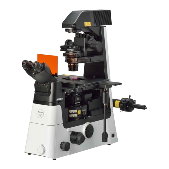
- Page 1 M702 E 21.2.NF.8 (1/2) *M702EN08* Inverted Research Microscope Instruction Manual...
-
Page 3: Introduction
The equipment described in this manual might differ from the actual product in its appearance. • Although every effort has been made to ensure the accuracy of this manual, errors or inconsistencies might remain. If you notice any points that are unclear or incorrect, please contact your local Nikon representative. •... -
Page 4: Table Of Contents
Contents Contents Introduction ..............................i Safety Precautions ............................vii Meaning of Symbols Used on the Product ................... vii WARNING and CAUTION Symbols Used in This Manual ............viii WARNING ..........................ix CAUTION ..........................xiv Handling of This Product ........................... xvii Chapter 1 Names of Parts and Their Functions .................. - Page 5 Contents 3.3.6 Operating the Contrast Shield (Optional) ............... 37 3.3.7 Using the D-LH/LC Precentered Lamphouse ..............38 Using the Condenser Section ...................... 41 3.4.1 Selecting a Suitable Condenser ..................41 3.4.2 Elevating the Condenser ....................42 3.4.3 Adjusting the Position of the Condenser (Centering) ............. 42 3.4.4 Using an Oil Immersion Condenser Lens ...............
- Page 6 Contents 3.15 Using a Centering C-mount Adapter .................... 78 Chapter 4 Microscopy Techniques ......................79 Details of Diascopic Bright-field (BF) Microscopy ................ 80 4.1.1 Principles of BF Microscopy ................... 80 4.1.2 Optical Elements Required for BF Microscopy ............... 81 4.1.3 Combination of Optical Elements ...................
- Page 7 Contents 6.1.3 Cleaning Off Immersion Oil ................... 117 6.1.4 Decontaminating the Product ..................117 Storing the Product ........................118 Regular Inspection (Charged) ....................118 Chapter 7 Assembly of the Devices ......................119 Ti2-U System Configuration ....................... 121 List of Components ........................123 Installing the Microscope Main Body (Base) ................
- Page 8 Contents 7.15.1 Position of Each Connector ..................170 7.15.2 Clamping Cables ......................171 7.16 Attaching Objectives ........................172 7.16.1 Attaching CFI60 Objectives ..................172 7.16.2 Parfocal Adjustment of Objectives without Correction Collar ........173 7.17 Attaching a Specimen Holder ..................... 175 7.17.1 Attaching a Specimen Holder for the Manual Stage .............
-
Page 9: Safety Precautions
Safety Precautions Safety Precautions Although this product is designed and manufactured to be completely safe during use, incorrect usage or failure to follow the safety instructions provided may cause personal injury or property damage. To ensure correct usage, carefully read this manual and the instruction manuals of products used together before using the product. -
Page 10: Warning And Caution Symbols Used In This Manual
Safety Precautions Symbol Description Hot surface Caution for heat symbol This symbol label is attached on the front and top surfaces of the motorized shutter unit to remind the user of the following precautions: • The motorized shutter may become hot if closed Hot surface during a period of illumination. - Page 11 Disassembly may cause malfunction and/or electrical shock, and will lead to the forfeiture of all claims against warranty. Do not disassemble any part other than those described in this manual. If you experience any problem with the microscope, contact your local Nikon representative. Confirm the input voltage.
- Page 12 Notes on handling flammable solvents The following flammable solvents are used with this product: • Immersion oil (Nikon immersion oil for oil immersion lenses) • Absolute alcohol (ethyl alcohol or methyl alcohol for cleaning optical components) • Petroleum benzine (for removing immersion oil) •...
- Page 13 Safety Precautions WARNING 10. Photobiological safety This product is designed and manufactured in accordance with the IEC62471 standard “Photobio- logical Safety of Lamps and Lamp Systems.” Light emitted from the dia-illumination section of the Ti2-U main body The photobiological safety of light emitted from the dia-illumination section (aperture of the con- denser lens) is classified into the risk group shown in the table below.
- Page 14 Safety Precautions WARNING 11. Do not attempt to view the illumination section. Dia-illumination and epi-illumination of the Ti2-U main body The following warning label indicating the highest risk: Risk group 3 in photobiological safety of the Ti2-U main body is affixed on the side surface of the dia-illumination section to remind the user of the following three precautions.
- Page 15 Safety Precautions WARNING 12. Cautions on replacing the filter cube The following caution label is affixed to the cover of the fluorescence filter cube replacement port of the FL turret. This label reminds you of the following precautions: Close the shutter before opening the cover of the filter cube slot.
- Page 16 Then, wipe off any moisture with a dry cloth. If any liquid or foreign matter gets inside the microscope, stop using the microscope, and contact your local Nikon representative. There is a higher possibility that liquid is accidentally spilled on the objective and the nosepiece which are positioned immediately below the stage.
- Page 17 Safety Precautions CAUTION Notes on cleaning • Petroleum benzine and absolute alcohol used for cleaning are highly flammable. Handle them with due care, keep them away from fire or sparks, and do not use them when turning the pow- er switch on and off. •...
- Page 18 Safety Precautions CAUTION 10. Cautions on carrying the microscope (continued) Before carrying the microscope, always remove the following protruding devices. - Camera - TI-BPU back port unit - Epi-fluorescence attachment (TI2-LA-BM, TI2-LA-BF, TI2-LA-BS) • Before carrying the microscope, remove detachable cables, and secure moving parts. - Be sure to clamp the pillar for dia-illumination.
-
Page 19: Handling Of This Product
In this case, Nikon recommends turning off the room light immediately above the microscope before use. • Install this product at least 10 cm away from nearby walls. - Page 20 When the fluorescence filter cubes are not to be used, Nikon recommends storing them in a desiccator or sealed container with a desiccant.
-
Page 21: Chapter 1 Names Of Parts And Their Functions
Chapter 1 Names of Parts and Their Functions Chapter 1 Names of Parts and Their Functions Chapter Names of Parts and Their Functions This chapter describes the name and function of each unit and operation section of the microscope system in a basic configuration. -
Page 22: System Configuration And Names Of Components
Chapter 1 Names of Parts and Their Functions System Configuration and Names of Components This manual describes the basic configuration of the microscope consisting of the following components: Diascopic illumination lamphouse Photobiological safety label Polarizer Pillar for dia-illumination Condenser turret Condenser lens Objective Shielding plate... - Page 23 In this manual, generic names are used to provide a general description of each device, and product names and model numbers are used to provide product-specific descriptions. Component name (generic) Product Model Main body Inverted Research Microscope ECLIPSE Ti2-U ECLIPSE Ti2-U Tube ER tube TC-T-ER Tube base unit...
-
Page 24: Nomenclature And Functions
Chapter 1 Names of Parts and Their Functions Nomenclature and Functions 1.2.1 Dia-illumination Section Fixed filter slot Lamphouse for Dia illumination Up to 2 filters can be inserted. ☞ Control this lamphouse by the 3.3.4) dia-illumination ON/OFF button and the light control volume. ☞... -
Page 25: Condenser Unit And Polarizer
Chapter 1 Names of Parts and Their Functions 1.2.2 Condenser Unit and Polarizer Condenser refocusing clamp Set the lower limit for the condenser's Polarizer vertical move. Change dia-illumination to polarized • Tighten the clamp: Set the lower illumination. limit at the current position. ☞... -
Page 26: Tube And Eyepiece
Chapter 1 Names of Parts and Their Functions 1.2.3 Tube and Eyepiece Ultraviolet light shielding plate This plate prevents ultraviolet light Eyepiece or strong light emitted from the Diopter can be adjusted according to objective from entering your eyes. the observer's eyesight. ☞... -
Page 27: Stage
Chapter 1 Names of Parts and Their Functions 1.2.5 Stage Holder mount The user can mount a specimen holder suitable for the specimen to be used. This figure shows a universal holder mounted. ☞ 3.8.1) Manual stage The stage can be moved with the stage handle. -
Page 28: Nosepiece
Chapter 1 Names of Parts and Their Functions 1.2.6 Nosepiece Objective ☞ 3.10) DIC slider slot Insert the DIC slider in this slot for DIC microscopy. ☞ 3.9.2) Nosepiece When switching the objective, turn the turret on the nosepiece. tter the shu cov er Clo se... -
Page 29: Fl Turret And Analyzer
Chapter 1 Names of Parts and Their Functions 1.2.8 FL Turret and Analyzer Turret address indication This indicates the address of the filter cube currently in the optical Turret ring path. When switching the filter cube, turn The address is displayed on the the turret ring until it clicks. -
Page 30: Epi-Fluorescence Attachments
Chapter 1 Names of Parts and Their Functions 1.2.9 Epi-fluorescence Attachments Epi-fluorescence attachment described in this manual This manual describes the following combination of units as the basic configuration. • TI2-LA-BF fixed main branch (Ti2-LAPP system) • TI2-LA-FL-2 EPI-FL module (Ti2-LAPP system) •... - Page 31 Chapter 1 Names of Parts and Their Functions Epi-fluorescence attachment (combination of a main branch, a sub branch, and two EPI-FL modules) When a main branch and a sub branch are used, multiple epi-illumination modules can be mounted. Switching the optical path of the main branch switches between the illumination modules mounted on the main branch and the illumination module mounted on the sub branch.
-
Page 32: Operation Sections Of The Microscope Main Body
Chapter 1 Names of Parts and Their Functions Operation Sections of the Microscope Main Body 1.3.1 Front Operation Panel Intermediate magnification dial Use this dial to switch the magnification of the entire microscope between 1.0x and 1.5x. ☞ 3.2.2) Front operation panel 1.3.2 Right and Left Operation Panels Coarse-focus knob torque... -
Page 33: Power Switch
Chapter 1 Names of Parts and Their Functions 1.3.3 Power Switch This power switch is for the Ti2-U main body. For details on the procedure for turning on the power, see "3.1 Power-related Operation." tte r the shu cov er Clo se ng the op eni... - Page 34 Chapter 1 Names of Parts and Their Functions This page is intentionally blank.
-
Page 35: Chapter 2 Microscopy
• Episcopic fluorescence (Epi-FL) microscopy (☞ 2.4) • Diascopic dark-field (DF) microscopy (☞ 2.5) • Nikon Advanced Modulation Contrast (NAMC) microscopy (☞ 2.6) System configuration The microscopy procedure is described based on a microscopy system in the basic configuration described in “Chapter 1 Names of Parts and Their Functions.”... -
Page 36: Diascopic Bright-Field (Bf) Microscopy
Chapter 2 Microscopy Diascopic Bright-field (BF) Microscopy Configure the microscope to the basic Set a sample and focus on it. state. 2-1 Open the dia-illumination shutter, and close 1-1 Turn on the power to the system. the FL turret shutter. ☞... - Page 37 Chapter 2 Microscopy Diascopic Bright-field (BF) Microscopy (Continued) Change the objective and observe the Center the condenser. specimen. 3-1 Turn the field diaphragm knob until the dia 4-1 Change the objective to the objective with a field diaphragm image becomes visible in the specified magnification.
-
Page 38: Diascopic Phase Contrast (Ph) Microscopy
Chapter 2 Microscopy Diascopic Phase Contrast (Ph) Microscopy Set up for Ph microscopy and adjust the phase Focus on the sample with BF plate ring and annular diaphragm. microscopy. 1.1 Perform the procedure from step to step 2-1 Change the objective to the objective for Ph in “2.1 Diascopic Bright-field (BF) Mi- microscopy. - Page 39 Chapter 2 Microscopy Diascopic Phase Contrast (Ph) Microscopy (Continued) Perform Ph microscopy. 3-1 Fully open the dia aperture diaphragm. ☞ [g] Aperture diaphragm open/close lever ( 3.4.5) ▼ 3-2 Adjust the size of the dia field diaphragm image. ☞ [h] Field diaphragm dial ( 3.3.3) ▼...
-
Page 40: Diascopic Dic / Imsi Microscopy
Chapter 2 Microscopy Diascopic DIC / IMSI Microscopy Set up for DIC microscopy / IMSI microscopy and Focus on the sample with BF adjust the azimuth of the polarizing plate. microscopy. 1-1 Check that the vessel of the sample is 2-1 Change the objective to the objective for DIC suitable for DIC / IMSI microscopy. - Page 41 Chapter 2 Microscopy Diascopic DIC / IMSI Microscopy (Continued) Perform DIC microscopy. 3-1 Place the condenser module for DIC 2-10 Loosen the clamp screw on the polarizer. microscopy or IMSI microscopy and the DIC ☞ [g] Polarizer ( 3.5.1) slider into the optical path. ▼...
-
Page 42: Episcopic Fluorescence (Epi-Fl) Microscopy
Chapter 2 Microscopy Episcopic Fluorescence (Epi-FL) Microscopy Change illumination to epi, set a sample, and Configure the microscope to the basic state. focus on it. 1-1 Turn on the power to the system. 2-1 To prevent the dia-illumination LED from emitting autofluorescence due to ☞... - Page 43 Chapter 2 Microscopy Episcopic Fluorescence (Epi-FL) Microscopy (Continued) Adjust the epi field diaphragm. Perform Epi-FL microscopy. 3-1 Turn the epi field diaphragm knob until the 4-1 Change the objective to the objective for field diaphragm image becomes visible in the fluorescence microscopy with a specified field of view.
-
Page 44: Diascopic Dark-Field (Df) Microscopy
Chapter 2 Microscopy Diascopic Dark-field (DF) Microscopy Configure the microscope to the basic Set a sample and focus on it. state. 2-1 Open the dia-illumination shutter, and close 1-1 Turn on the power to the system. the FL turret shutter. ☞... - Page 45 Chapter 2 Microscopy Diascopic Dark-field (DF) Microscopy (Continued) Adjust the condenser position to set up for DF Perform DF microscopy. microscopy. 3-1 Stop down the dia field diaphragm. 4-1 Change the objective to the objective with a ☞ specified magnification. [k] Field diaphragm dial ( 3.3.3) ☞...
-
Page 46: Namc Microscopy
[d] Centering telescope (☞ 3.6.4) ▼ Configuration of the microscope 2-7 Adjust the azimuth of the polarizer for To conduct Nikon Advanced Modulation Contrast (NAMC) NAMC/IMSI so that two slit diaphragms can microscopy, a polarizer for NAMC/IMSI, a condenser module be seen. - Page 47 Chapter 2 Microscopy NAMC Microscopy (Continued) Perform NAMC microscopy. 2-10 Adjust the position of the slit diaphragm. 3-1 Fully open the dia aperture diaphragm. ☞ ☞ [g] NAMC condenser module ( 3.4.8) [h] Aperture diaphragm open/close lever ( 3.4.5) Adjust the position to cause the portion of the slit ▼...
- Page 48 Chapter 2 Microscopy This page is intentionally blank.
-
Page 49: Chapter 3 Usage Of Components
Chapter 3 Usage of Components Chapter 3 Usage of Components Chapter Usage of Components This chapter provides details on how to use each module and device in the Ti2-U main body. CAUTION • Before using the product, thoroughly read the “Safety Precautions” at the beginning of this manual, and heed all warnings and cautions written therein. -
Page 50: Power-Related Operation
Chapter 3 Usage of Components Power-related Operation This section describes how to turn on and off the power to the microscope. Turning on the power to the microscope When turning on the power to the microscope, follow steps 1 and 2 in order. (1) Peripheral devices requiring dedicated power supply •... -
Page 51: Optical Parts In The Microscope Main Body
Chapter 3 Usage of Components Optical Parts in the Microscope Main Body 3.2.1 Switching the Output Port The optical image output port can be switched by setting the optical path changeover dial on the right side of the microscope to the required index mark (two protrusions) position. -
Page 52: Switching The Magnification Of The Device With The Intermediate Magnification Dial
• The settings of the intermediate magnification dial are valid for all optical image output ports (except the optional back port). • By replacing the 2nd tube lens inside the microscope, the magnification when the intermediate magnification dial is rotated to 2.0x can be changed. For replacement of the 2nd tube lens, contact your local Nikon representative. -
Page 53: Using The Dia-Illumination Section
Chapter 3 Usage of Components Using the Dia-illumination Section 3.3.1 Opening/Closing the Dia-Illumination Shutter The dia-illumination section has a shutter for blocking the optical path. Operation: Dia-illumination shutter Dia-illumination shutter knob Turn to the O (Open) side Open Dia-illumination Turn to the C (Close) side Close shutter knob... -
Page 54: Adjusting The Dia Field Diaphragm
Chapter 3 Usage of Components 3.3.3 Adjusting the Dia Field Diaphragm Field diaphragm is intended to restrict the observation range by changing the irradiation range of the illumination. Adjust the field diaphragm using the field diaphragm (F.S.) dial of the dia-illumination section. -
Page 55: Using A Filter For Dia-Illumination
Chapter 3 Usage of Components 3.3.4 Using a Filter for Dia-illumination Fixed Filter Up to two filters of any type can be inserted into the Optical path cover fixed filter slot of the dia-illumination section. For details on the procedure for setting the filter, see “7.8.3 Attaching a Fixed Filter for Dia-illumination.”... -
Page 56: Using The Dia-Illumination Pillar
• Be careful not to touch the lamphouse or its periphery as they might be very hot. Tilting clamp knob Nikon recommends tightening the pillar tilting clamp knob on the rear of the pillar to prevent the pillar from falling unintentionally even though the pillar is usable with the clamp released. -
Page 57: Operating The Contrast Shield (Optional)
Chapter 3 Usage of Components 3.3.6 Operating the Contrast Shield (Optional) The optional contrast shield is a device that blocks the ambient light irradiated from the above. For fluorescence microscopy, close the light shielding plate by operating the open/close knob. ... -
Page 58: Using The D-Lh/Lc Precentered Lamphouse
Chapter 3 Usage of Components 3.3.7 Using the D-LH/LC Precentered Lamphouse In place of the standard dia LED lamphouse, a D-LH/LC precentered D-LH/LC precentered lamphouse, which uses a lamphouse halogen lamp, can be attached. Connect D-LH/LC with the TI-PS100W/A power supply 100-240V/A before use. - Page 59 Chapter 3 Usage of Components Operating the Precentered Lamphouse Control the precentered lamphouse using the dia-illumination ON/OFF button and brightness adjuster on the left side of the microscope. Dia-illumination ON/OFF button Operation: Turning the lamp on or off Dia-illumination Dia-illumination Dia-illumination ON/OFF button...
- Page 60 Chapter 3 Usage of Components Using a motorized dia-illumination shutter When using a precentered lamphouse, an NI-SH-E Precentered motorized shutter can be attached to the lamphouse dia-illumination section. The motorized shutter can Motorized shutter be opened and closed with the NI-SH-CON controller for motorized shutter.
-
Page 61: Using The Condenser Section
Chapter 3 Usage of Components Using the Condenser Section 3.4.1 Selecting a Suitable Condenser The following four types of condensers can be used with this microscope: Select a condenser suitable for microscopy. Condenser turret (system condenser) Condenser module Up to seven condenser modules can be attached. Aperture replacement port Microscopy techniques can be switched by turning... -
Page 62: Elevating The Condenser
Chapter 3 Usage of Components 3.4.2 Elevating the Condenser Turn the condenser focus knob to vertically move the condenser so that the field diaphragm image can be seen clearly in the field. The movement of the condenser can also be limited so that it does not go below the designated position. -
Page 63: Using An Oil Immersion Condenser Lens
Chapter 3 Usage of Components 3.4.4 Using an Oil Immersion Condenser Lens When using the TI2-C-LHO HNA oil lens, use immersion oil to immerse between the prepared specimen slide and the top lens. Spread immersion oil, about the size of the diameter of the tip of the condenser lens, on the glass slides (or cover glass) of the prepared specimen, and then slowly lower the condenser... -
Page 64: Adjusting The Diascopic Aperture Diaphragm
Chapter 3 Usage of Components 3.4.5 Adjusting the Diascopic Aperture Diaphragm The aperture diaphragm adjusts the numerical aperture of the illumination system. Adjust the aperture diaphragm using the aperture diaphragm open/close lever of the condenser. Operation: Aperture diaphragm Aperture Aperture diaphragm open/close lever diaphragm... -
Page 65: Switching The Condenser Module
Chapter 3 Usage of Components 3.4.6 Switching the Condenser Module Condenser turret (system condenser) When switching the condenser module, manually turn the turret ring to place the module into the optical path. Operation: Turret ring Condenser turret Turn until it clicks into The front or rear module Position display position. - Page 66 Chapter 3 Usage of Components Usable condenser module list The following table shows the condenser modules mountable on the condenser turret and the condense slider. Table Condenser module list Microscopy Remarks Name technique ND filter TC-C-ML-PHL LWD Module TC-C-ME-PHL ELWD Module TC-C-ML-PH1 LWD Module TI2-C-MC-PH1 CLWD Module for PH1 TC-C-ME-PH1 ELWD Module...
-
Page 67: Adjusting The Ph Module Position
Chapter 3 Usage of Components 3.4.7 Adjusting the Ph Module Position It is necessary to center the annular diaphragm of the Ph module. Center the annular diaphragm using the centering telescope. Remove one eyepiece, attach the centering telescope, and then focus on the ring diaphragm image by turning the eyepiece section of the centering telescope. -
Page 68: Adjusting The Namc Module
Chapter 3 Usage of Components 3.4.8 Adjusting the NAMC Module Before performing NAMC microscopy, adjust the orientation of the modulator of the NAMC objective, and then adjust the position and the orientation of the NAMC module accordingly. Image quality and adjustment of the modulator of the NAMC objective NAMC objectives have a modulator with a dark region and gray region pattern as shown on the right. - Page 69 Chapter 3 Usage of Components NAMC condenser slit image and slit diaphragm adjustment In the NAMC condenser module, there are two apertures (slit diaphragms) indicated by (1) and (2) in Dark region (D) the right figure, and a space called “bridge” indicated Objective pupil by (3) between the apertures.
-
Page 70: Using The Elwd-S Condenser
Chapter 3 Usage of Components 3.4.9 Using the ELWD-S Condenser Switching the condenser module The ELWD-S condenser allows BF microscopy and Ph Centering knob microscopy. Turn the turret manually to place the clamp screw module into the optical path. (both sides) ... -
Page 71: Using The Polarizer And Analyzer
Chapter 3 Usage of Components Using the Polarizer and Analyzer 3.5.1 Using the Polarizer When performing a DIC microscopy, NAMC microscopy, or IMSI microscopy, attach a polarizer to the condenser mount and place a polarization plate into the optical path. The following two types of polarizers are usable: Supported microscopy Polarizer... - Page 72 Chapter 3 Usage of Components Attaching a polarizer and adjusting the azimuth (to form Crossed Nicols) 1. Place the polarizer on the condenser mount. Do not tighten the clamp screw at this stage. 2. Remove the DIC condenser module and the DIC slider from the optical path.
-
Page 73: Using The Analyzer
Chapter 3 Usage of Components 3.5.2 Using the Analyzer In DIC microscopy and IMSI microscopy, place the polarizer and analyzer in the optical path at the same time, orthogonalize the orientations of both, and conduct observation in the Cross Nicol state. Inserting and removing the analyzer slider ... -
Page 74: Using The Tube And The Objective
Chapter 3 Usage of Components Using the Tube and the Objective 3.6.1 Adjusting the Angle of the Binocular Part (ER tube) When using the ER tube (TC-T-ER), the angle of the binocular part is adjustable within the range of 15 to 45 degrees. -
Page 75: Adjusting The Diopter Of The Eyepiece
Chapter 3 Usage of Components 3.6.2 Adjusting the Diopter of the Eyepiece By turning the diopter correction collar of the Diopter eyepiece, the diopter of the eyepiece can be adjustment adjusted according to the observer's eyesight. collar Operation: Diopter adjustment Diopter collar Turn it clockwise. -
Page 76: Adjusting Interpupillary Distance
Chapter 3 Usage of Components 3.6.3 Adjusting Interpupillary Distance Adjust the distance between the objectives to match the distance between the eyes of the observer. This adjustment makes it easier to perform observation with both eyes. Operation: Distance between Binocular part eyepieces Adjust the pupillary distance... -
Page 77: Using The Tube Base Unit
Chapter 3 Usage of Components Using the Tube Base Unit 3.7.1 Switching the Optical Path of the Tube Base Unit (Tube Base Unit with Port) The eyepiece tube base unit with port has a side port Tube base for a camera. The optical path can be switched side port between the eyepiece section and the side port by Optical path... -
Page 78: Using The Stage
Chapter 3 Usage of Components Using the Stage 3.8.1 Setting a Sample on the Manual Stage By attaching a specimen holder to the TC-S-SR manual stage, various types of specimens can be observed. Use a specimen holder appropriate for the specimen to be used. -
Page 79: Setting A Sample On The Plain Stage/Gliding Stage
Chapter 3 Usage of Components Using the 35-mm-diameter petri dish holder This holder is for use with 35-mm-diameter petri Fit it into the hole. dishes. Operation: • Insert the 35 mm petri dish into the central hole. 35 mm petri dish •... -
Page 80: Moving A Sample On The Stage
If the gliding stage is used beyond its warranty period, the power required to operate it might change. In that case, it is possible to restore to the original status by maintenance work (at a fee). For details, contact your local Nikon representative. -
Page 81: Using The Nosepiece
Chapter 3 Usage of Components Using the Nosepiece 3.9.1 Turning the Nosepiece to Switch the Objective When switching objectives, manually turn the turret ring of the nosepiece clockwise or counterclockwise Objective until it clicks into position. Operation: Turn until it clicks into position. -
Page 82: Using The Objective
Adjustment of the correction collar • Nikon recommends writing down the location of the correction collar of the best resolution. That will serve as a reference when a vessel with a different thickness of the cover glass is used. - Page 83 Chapter 3 Usage of Components Designated cover-glass thickness Objectives are labeled with the supported cover Glass slide glass thickness. For instance, “∞/0.17” indicates that a designated cover glass thickness of 0.17 mm. Cover glass ■ Glass thickness of 0.17 mm: When using the objective labeled “0.17”, use a cover glass with a thickness of 0.17 mm.
-
Page 84: Using Oil Immersion Objectives
• When using an oil immersion objective, fill the “Oil” mark gap between the tip of the objective and the specimen with oil (Nikon immersion oil). When performing fluorescence microscopy using an oil immersion objective for fluorescence mi- croscopy, use low-fluorescence oil. -
Page 85: Using A Water Immersion Objective
Chapter 3 Usage of Components CAUTION Take due care when handling absolute alcohol or petroleum benzine, as they are highly inflammable. Do not bring any ignition source or use the power switch near absolute alcohol or petroleum benzine. Checking for air bubbles •... -
Page 86: Using An Objective With A Diaphragm
Chapter 3 Usage of Components 3.10.4 Using an Objective with a Diaphragm When performing DF microscopy, use of an objective with diaphragm allows numerical aperture (NA) adjustment of the objective according to the NA of the DF condenser. Operation: Check the minimum NA of the DF condenser, and Diaphragm “Iris”... -
Page 87: Using The Focusing Device
Chapter 3 Usage of Components 3.11 Using the Focusing Device 3.11.1 Focusing on the Sample Turning the focus knobs on the microscope main body moves the objective vertically, enabling the user to focus on the specimen. The focus knobs are divided into the following two types. -
Page 88: Using The Coarse-Focus Knob Torque Adjustment Ring
Chapter 3 Usage of Components Using the focus knob To avoid malfunction, never perform the following operations: • Rotate the right and left focus knobs in opposite directions. • Attempt to rotate the coarse-focus or fine-focus knob beyond the rotation limit. 3.11.2 Using the Coarse-Focus Knob Torque Adjustment Ring The focus knob on the left side of the microscope is... -
Page 89: Using The Objective Refocusing Lever
Chapter 3 Usage of Components 3.11.3 Using the Objective Refocusing Lever The focus knob on the right side of the microscope is Objective equipped with an objective refocusing lever for refocusing lever Clamp setting the current objective position as the rotation limit of the coarse-focus knob by turn the lever to the vertical position (CLAMP). -
Page 90: Using The Fl Turret
Chapter 3 Usage of Components 3.12 Using the FL turret 3.12.1 Switching the Filter Cube Address When switching the filter cube, turn the turret ring Turret ring indication manually to the right or left and stop it at the click position. -
Page 91: Selecting Filter Cubes
For details on replacing the optical components, see “7.5.3, Replacing an Excitation Filter, a Barrier Filter, and a Dichroic Mirror.” C-FL-HQ filter cube Nikon provides a C-FL-HQ filter cube that does not include Barrier filter attachment position optical elements. Select a desired combination of three... -
Page 92: Using The Epi-Fluorescence Attachment
Chapter 3 Usage of Components 3.13 Using the Epi-fluorescence Attachment 3.13.1 Adjusting the Aperture Diaphragm of the Epi-fluorescence Attachment The aperture diaphragm is used to adjust the number of illumination apertures. In an optical Aperture diaphragm open/close lever system for the epi-fluorescence attachment, the aperture diaphragm adjusts the brightness of the image and the amount of stray light. -
Page 93: Using The Filter Slider
Chapter 3 Usage of Components 3.13.2 Using the Filter Slider Up to two filters with a diameter of 25 mm and a thickness of up to 5.5 mm can be attached to the filter slider. Operation: Filter slider Filter The front filter (on the Push in lever side) -
Page 94: Using The Field Diaphragm Slider
Chapter 3 Usage of Components 3.13.3 Using the Field Diaphragm Slider Inserting or removing the field diaphragm The field diaphragm is a diaphragm for restricting the illumination range. The entire field diaphragm can be placed into or removed from the optical path by inserting or removing the field diaphragm slider. - Page 95 Chapter 3 Usage of Components Adjust the position of the field diaphragm (centering adjustment) Focus on the sample in episcopic BF. Field diaphragm image Stop down the field diaphragm using the field diaphragm open/close lever. Turn the field diaphragm centering screw using a 2 mm hexagonal screwdriver to move the center of the field diaphragm image to the center of the field.
-
Page 96: Switching The Optical Path Of The Main Branch
The optical path of the main branch can be switched by inserting or removing the internal switching mirror. Although only full mirrors and half mirrors are provided by Nikon, a commercially-available dichroic mirror can also be attached according to the microscopy technique. -
Page 97: Using A Back Port Unit (Optional)
Chapter 3 Usage of Components 3.14 Using a Back Port Unit (Optional) An additional camera device can be mounted by Back port unit attaching a TI-BPU back port unit to the back port on C mount adapter the rear of the illumination pillar. Because a filter cube (dichroic mirror) in the FL turret is used to split the optical path to the back port, the FL turret can be used to select a wavelength. -
Page 98: Using A Centering C-Mount Adapter
Chapter 3 Usage of Components 3.15 Using a Centering C-mount Adapter Focusing and centering of the camera can be achieved using a centering C-mount adapter, if it is used for attaching the camera device. Centering screws (x 2) Focus adjustment fixing screw (x 1) Focus adjustment part (turn to adjust) Centering fixing screw (bottom, x 1) -
Page 99: Chapter 4 Microscopy Techniques
Chapter 4 Microscopy Techniques Chapter 4 Microscopy Techniques Chapter Microscopy Techniques This chapter explains the principles of each microscopy, and optical elements required for implementing each microscopy, and combinations of optical elements. -
Page 100: Details Of Diascopic Bright-Field (Bf) Microscopy
Chapter 4 Microscopy Techniques Details of Diascopic Bright-field (BF) Microscopy 4.1.1 Principles of BF Microscopy BF microscopy is a method of observing stained Light emitted from the aperture diaphragm is specimens, and serves as the basic method for converted by the condenser lens into a parallel implementing other microscopies. -
Page 101: Optical Elements Required For Bf Microscopy
Chapter 4 Microscopy Techniques Advantages of BF Microscopy • Because specimens can be illuminated brightly, this microscopy is suitable for stained specimens. This microscopy is also appropriate for focusing or searching for observation objects as a preparatory step for other microscopies. •... -
Page 102: Combination Of Optical Elements
Chapter 4 Microscopy Techniques Condenser lens Condenser lenses that allow BF microscopy are as follows: LWD condenser lens ELWD condenser lens CLWD condenser lens HNA condenser lens (dry) HNA condenser lens (oil) Usable condenser lens LWD condenser ELWD condenser CLWD condenser HNA condenser HNA condenser lens... -
Page 103: Details Of Phase Contrast (Ph) Microscopy
Chapter 4 Microscopy Techniques Details of Phase Contrast (Ph) Microscopy 4.2.1 Principles of Ph Microscopy Ph microscopy is a method of observing colorless, The light emitted from the light source is annularly transparent specimens such as living cells in an narrowed by the annular diaphragm. -
Page 104: Optical Elements Required For Ph Microscopy
Chapter 4 Microscopy Techniques Advantages of Ph microscopy • Ph microscopy is highly effective in detecting phase contrast. It is said that an optical path phase contrast of up to about 1/1000λ can be detected. • The image view remains the same regardless of the direction of the specimen placed. •... - Page 105 Chapter 4 Microscopy Techniques Characteristics of Ph objectives Ph objective View Contrast Latitude Application examples Spores of fungus, Phase contrast ordinary living cells, and absorbing Half tone thick specimens, objects (stained (the use fungus, stained Generally, objects with a objects) in the This is range is wide) specimens, insect...
-
Page 106: Combination Of Optical Elements
Chapter 4 Microscopy Techniques Condenser lens Condenser lenses that allow Ph microscopy are as follows: LWD condenser lens ELWD condenser lens CLWD condenser lens HNA condenser lens (dry) HNA condenser lens (oil) Specifications and details of condenser lenses Condenser turret (system condenser) HNA condenser slider LWD condenser ELWD condenser... -
Page 107: Details Of Diascopic Dic And Imsi Microscopies
Chapter 4 Microscopy Techniques Details of Diascopic DIC and IMSI Microscopies 4.3.1 Principles of DIC Microscopy DIC microscopy is a method of observing colorless, blocked by polarizing plate 2 (analyzer) on which transparent specimens such as living cells in an polarizing plate 1 and the optical axis intersect at unstained way using dia-illumination. -
Page 108: Optical Elements Required For Dic Microscopy
Chapter 4 Microscopy Techniques Advantages of DIC microscopy • This microscopy enables observation of the specimens thicker than those for Ph microscopy. • Unlike Ph microscopy, this microscopy is free from a halo phenomenon in a boundary of a large structure and therefore allow minute structure observation. - Page 109 Chapter 4 Microscopy Techniques DIC polarizer (NAMC/IMSI polarizer) Polarizers are classified as DIC polarizers and NAMC/IMSI polarizers. DIC polarizer NAMC/IMSI polarizer Polarizer DIC condenser module (IMSI condenser module) Use the DIC condenser module by attaching it to the Prism name condenser turret.
-
Page 110: Combination Of Optical Elements
Chapter 4 Microscopy Techniques DIC slider Insert the DIC slider in the DIC slider slot of the nosepiece. The combination of a DIC condenser module and a DIC slider depends on objectives to be used. Use a correct combination. Prism name DIC slider (DIC prism for objectives) Analyzer Analyzers used for DIC microscopy or IMSI microscopy include analyzer slider and analyzer cube. - Page 111 Chapter 4 Microscopy Techniques With the LWD condenser lens LWD condenser lens Standard combination High contrast High resolution Objective Condenser Condenser Condenser DIC slider DIC slider DIC slider module module module Plan Apo 10XA Plan Fluor 10X N1 Dry Plan Apo λ...
- Page 112 Chapter 4 Microscopy Techniques With the high NA condenser lens Dry-type high NA condenser lens Oil-type high NA condenser lens Standard combination High resolution Standard combination High resolution Objective Condenser DIC slider Condenser DIC slider Condenser Condenser DIC slider DIC slider module module...
- Page 113 Chapter 4 Microscopy Techniques Combination of IMSI objectives and DIC prisms (condenser side/objective side) To perform IMSI microscopy, it is necessary to use a correct combination of an IMSI objective, and DIC prisms (condenser side/objective side). Referring to the following table, check the correct combination of the objective, the condenser module and the DIC slider, and then place the optical components of the correct combination in the optical path.
-
Page 114: Details Of Episcopic Fluorescence (Epi-Fl) Microscopy
Dichroic Excitation filter Noise terminator (BA filter) mirror (EX filter) Noise terminator—a unique optical system in NIKON fluorescent microscopes—provides high-contrast fluorescent images by practically eliminating excitation light (not reflected by the dichroic mirror) from the observation optical system. Wavelength (nm) -
Page 115: Optical Elements Required For Epi-Fl Microscopy
Chapter 4 Microscopy Techniques Advantages of Epi-FL microscopy • Microscopy for only localization and behaviors of interest can be performed by applying fluorescent labeling to specific tissues, cells, or molecules. Use of multiple fluorescent labels enables several objects of interest to be observed simultaneously. •... -
Page 116: Combination Of Optical Elements
Chapter 4 Microscopy Techniques Light source The fluorescence LED illumination system is used for the epi-fluorescence attachment. For details on wavelength characteristics of the light source, see the instruction manual supplied with the light source. Filter cube The fluorescent filter cube (mounted on the turret) Barrier filter consists of three types of optical components: the excitation filter (EX filter), the barrier filter (BA filter),... -
Page 117: Details Of Diascopic Dark-Field (Df) Microscopy
Chapter 4 Microscopy Techniques Details of Diascopic Dark-field (DF) Microscopy 4.5.1 Principles of DF Microscopy DF microscopy is a technique for improving the contrast of unstained specimens using oblique illumination. Illumination Annular Unlike other diascopic microscopy techniques (Ph or diaphragm DIC) that form images of dark specimens on a bright background, this microscopy technique enables bright specimens to be visualized in high contrast on... - Page 118 Chapter 4 Microscopy Techniques Objective DF microscopy requires objectives (excluding 2x and 4x) with NA smaller than the minimum NA of the condenser. Using an objective with a diaphragm, the diaphragm in the objective can be adjusted, enabling DF microscopy. TI-DF dark-field condenser adapter Use the TI-DF dark-field condenser adapter to mount a darkfield condenser lens.
-
Page 119: Combination Of The Optical Elements Required For Df Microscopy
Chapter 4 Microscopy Techniques 4.5.3 Combination of the Optical Elements Required for DF Microscopy DF microscopy uses the following components. Condenser turrets or condenser sliders are not used. • Dark-field condenser adapter (TI-DF) • Darkfield condenser (darkfield condenser Oil or darkfield condenser Dry) •... -
Page 120: Details Of Namc Microscopy
Chapter 4 Microscopy Techniques Details of NAMC Microscopy 4.6.1 Principles of NAMC Microscopy NAMC microscopy (Nikon Advanced Modulation the specimen. The illumination changes the direction Contrast) is a method of observing colorless, of movement according to the shape of the specimen. -
Page 121: Optical Elements Required For Namc Microscopy
Chapter 4 Microscopy Techniques 4.6.2 Optical Elements Required for NAMC Microscopy NAMC microscopy requires the following components as well as the status of bright field. • NAMC objective • TC-C-DICPNI NAMC/IMSI Polarizer • NAMC condenser module (to be attached to the slit diaphragm and the condenser turret) •... -
Page 122: Combination Of Optical Elements
Chapter 4 Microscopy Techniques NAMC condenser lens or LWD condenser lens The NAMC condenser lens or the LWD condenser lens is required for NAMC microscopy. NAMC condenser lens LWD condenser lens Specifications and details of condenser lenses NAMC condenser lens LWD condenser lens 0.52 Working distance... -
Page 123: Chapter 5 Troubleshooting
When using devices or components not described in this manual, see the appropriate manual for each device or component. If you detect problems that are not described in this chapter or the problem still persists after measures are taken, turn off the device and contact your local Nikon representative. -
Page 124: Troubleshooting For Microscopy Techniques
Chapter 5 Troubleshooting Troubleshooting for Microscopy Techniques 5.1.1 Common Microscopy Troubles Problem Check item Assorted shutters ⃞ Open the dia-illumination shutter. (☞ 3.3.1) ⃞ Open the contrast shield. (☞ 3.3.6) ⃞ Open the motorized shutter. (☞ 3.3.7) ⃞ Adjusting the filed diaphragm and the aperture diaphragm. (☞ 3.3.3, 3.4.5, 3.13.1, 3.13.3) ⃞... - Page 125 Chapter 5 Troubleshooting Problem Check item Specimen / stage ⃞ Check the orientation of the cover glass surface of the specimen. (☞ 3.10.1) ⃞ Check if the cover glass thickness is appropriate. (☞ 3.10.1) ⃞ If uneven blurring occurs, or an out-of-focus condition occurs as a result of stage movement, check whether the specimen is tilted.
- Page 126 Chapter 5 Troubleshooting Problem Check item Assorted shutters ⃞ Open the dia-illumination shutter. (☞ 3.3.1) ⃞ Open the contrast shield. (☞ 3.3.6) ⃞ Open the motorized shutter. (☞ 3.3.7) ⃞ Adjusting the filed diaphragm and the aperture diaphragm. (☞ 3.3.3, 3.4.5, 3.13.2, 3.13.4) ⃞...
-
Page 127: Troubles In Bf Microscopy
Chapter 5 Troubleshooting 5.1.2 Troubles in BF Microscopy ■ Clarity of images Problem Check item Light source / illumination ⃞ Adjust the brightness using the brightness adjuster. (☞ 3.3.2, 3.3.7) Condenser The image is dark. ⃞ Make sure to perform focusing and centering for the condenser precisely. (☞ 3.4.2, 3.4.3) ⃞... - Page 128 If the objective does not have a stopper, the tip of the lens cannot be turned. Do not try to forcibly pull it out, and instead contact your local Nikon representative. Specimen / stage ⃞...
-
Page 129: Troubles In Ph Microscopy
Chapter 5 Troubleshooting 5.1.3 Troubles in Ph Microscopy Problem Check item Nosepiece / objective ⃞ Place the Ph objective into the optical path. (☞ 3.9.1, 4.2.2) Condenser module ⃞ Place the Ph module (annular diaphragm) for Ph microscopy into the optical path. There is no contrast in the phase (☞... -
Page 130: Troubles In Dic And Imsi Microscopies
Chapter 5 Troubleshooting 5.1.4 Troubles in DIC and IMSI Microscopies Problem Check item Condenser ⃞ Turn the condenser turret to the regular position. (☞ 3.4.6) ⃞ For an HNA condenser slider, move the slider to the limit position. (☞ 3.4.6) A portion of the field of view is missing. -
Page 131: Troubles In Epi-Fl Microscopy
⃞ When using ultraviolet or violet excitation light, use the specified objective. Nosepiece / objective ⃞ Use low-fluorescent oil (Nikon DF immersion oil). (☞ 3.10.2) Specimen / stage ⃞ Use a low-fluorescent glass slide and cover glass. Camera ⃞... -
Page 132: Troubles In Namc Microscopy
Chapter 5 Troubleshooting 5.1.7 Troubles in NAMC Microscopy Problem Check item Polarizer ⃞ Place the polarizer into the optical path. (☞ 3.5.1, 4.6.2) Nosepiece / objective ⃞ Place the NAMC objective into the optical path. (☞ 3.9.1, 4.6.2) Condenser module ⃞... -
Page 133: Troubleshooting For The Units
Chapter 5 Troubleshooting Troubleshooting for the Units 5.2.1 Microscope Main Body Problem Check item Power cannot be turned on even when ⃞ Correctly connect the AC adapter and the power cord. (☞ 7.15.1) the power switch is pressed. ⃞ The AUC port might be set to R80 (right side port 80%, eyepiece observation port No instructions on the AUX port 20%) or L80 (left side port 80%, eyepiece observation port 20%) according to the specification at the time of purchase. -
Page 134: Pillar For Dia Illumination And Condenser
Chapter 5 Troubleshooting 5.2.3 Pillar for Dia Illumination and Condenser Problem Check item The field diaphragm image is invisible ⃞ Switch the objective to a lower-magnification objective. (☞ 3.9.1) even though the field diaphragm is ⃞ Focus on the condenser. (☞ 3.4.2) stopped down. -
Page 135: Chapter 6 Maintenance And Storage Of The Device
Chapter 6 Maintenance and Storage of the Device Chapter 6 Maintenance and Storage of the Device Chapter Maintenance and Storage of the Device This chapter describes how to maintain and store the device. Maintenance work done incorrectly could affect the performance of the product. When performing maintenance work on the product, follow the instructions in this chapter. -
Page 136: Cleaning The Device
Chapter 6 Maintenance and Storage of the Device Cleaning the Device Clean or disinfect the lenses and other components according to the following instructions. Cleaning tools • Blower • Soft brush • Soft cotton cloth, lens cleaning tissue, gauze, etc. •... -
Page 137: Cleaning The Lenses
Chapter 6 Maintenance and Storage of the Device 6.1.1 Cleaning the Lenses Keep the lenses free of dust, fingerprints, and other dirt. Any dirt on lenses and filters will degrade the image quality. If the lenses become dirty, clean them according to the following procedure. Cleaning off minor dirt (such as dust) (1) Blow dust off using an air blower. -
Page 138: Storing The Product
• Do not cover this product unless the power switch on the main body of the microscope has been turned off (set it to “o”) and the lamphouse becomes sufficiently cool to touch (for approximately 30 minutes). Regular Inspection (Charged) To maintain the performance of this product, Nikon recommends periodic inspections (chargeable service). -
Page 139: Chapter 7 Assembly Of The Devices
Chapter 7 Assembly of the Devices Chapter 7 Assembly of the Devices Chapter Assembly of the Devices This chapter presents the system configuration diagram and components list for the Ti2-U microscope, and also explains how to assemble devices. WARNING • Before assembling or connecting devices, thoroughly read “Safety Precautions” at the beginning of this manual, and heed all warnings and cautions written therein. - Page 140 Be sure to turn off the power to the microscope and peripheral units before connecting a cable. Cable connection • Nikon recommends connecting cables at the end of the assembly. For details on the connector positions, see “7.15 Connection of Each Cable.”...
-
Page 141: Ti2-U System Configuration
Chapter 7 Assembly of the Devices Ti2-U System Configuration NI-SH-CON Controller for Motorized Shutter * NI-SH-E Motorized Shutter Assorted filters NI-SHADI Motorized Shutter Adapter for Dia-Illumination TI-PS100W/A Power Supply TI2-D-SF Filter Slider for Dia 100-240V/A * Illumination D-LH/LC precentered lamphouse TI2-D-LHLED LED Lamp House for Dia Illumination TI2-D-PD Pillar for Dia Assorted polarizers... - Page 142 Chapter 7 Assembly of the Devices Assorted stage rings C-S-WC 96 Well Clamper TC-S-SC Stage Clip Assorted specimen holders for the manual stage TC-S-SR Stage TI-SP Plain Stage TC-S-GS Gliding Stage TC-S-SRF F Stage Assorted handles Assorted CFI60 objectives TI-PFW Parfocality Washer Set TI2-N-PT Nosepiece Protection Tray Assorted DIC sliders TI2-N-N Sextuple Nosepiece...
-
Page 143: List Of Components
Chapter 7 Assembly of the Devices List of Components The following table shows the components of the ECLIPSE Ti2-U microscope. Some components may be unavailable, depending on when you purchased this product. For details, contact your local Nikon representative. Device... - Page 144 Chapter 7 Assembly of the Devices Device Description Model Remarks Diascopic Filter slider for dia illumination TI2-D-SF Recommended when a D-LH/LC illumination precentered lamphouse is used for filter dia-illumination. Usable filters: • TI2-D-D 45 Diffuser • MF45 GIF • MF45 NCB11 •...
- Page 145 Select either 50:50 or 100:0 (total reflection). For the lower-tier main branch when Stage-up lens TI-LA-SUL a stage-up kit is used For details, contact your local Nikon representative. EPI-FL module TI2-LA-FL-2 Required for a combination of each branch and an LED light source...
- Page 146 Carrying handles TI-BCH Microscope carry handle Fix plate for CF TI2-FP For fixing base plates. For details, contact your local Nikon representative. T-BP/E20L80 prism For splitting optical paths. For details, contact your local Nikon representative. T-BP/E20R80 prism For splitting optical paths.
-
Page 147: Installing The Microscope Main Body (Base)
Chapter 7 Assembly of the Devices Installing the Microscope Main Body (Base) Notes on installation work As this product is heavy, make sure at least two people are available when performing installation work. When lifting the microscope main body (base), firmly hold it by gripping the recess in the front bottom part and the handhold position in the rear part. -
Page 148: Mounting The Tube Base Unit
Chapter 7 Assembly of the Devices Mounting the Tube Base Unit Mount the eyepiece tube base unit (TI2-T-BC or TI2-T-BC) on the microscope main body (base). (Tool: 4 mm hex wrench, supplied with the microscope main body) Place the tube base unit on the front part of Hex socket head cap the microscope main body (base) while screws (M5, x 4) -
Page 149: Fl Turret (Required For Epi-Fl Microscopy)
(FL2). As with the case in which only the first tier is used, mount and connect the turret and register filter cubes. Stage-up kits must be mounted by Nikon personnel. For details, contact your local Nikon representative. -
Page 150: Mounting A Filter Cube
Chapter 7 Assembly of the Devices 7.5.2 Mounting a Filter Cube Mount a filter cube on the FL turret. Precautions on mounting or removing a filter cube • Before mounting or removing a filter cube, make sure that the assembly of other devices has been completed. •... -
Page 151: Replacing An Excitation Filter, A Barrier Filter, And A Dichroic Mirror
• When thickness of filter is ≥3.5 mm and <4.5 mm Place the spacer as its rear side faces the retaining Cross section of the spacer ring. * When attaching a non-Nikon excitation filter, ask the manufacturer the attaching direction in advance. - Page 152 (downward). Replacement of the barrier filter * When attaching a non-Nikon barrier filter, ask the manufacturer the attaching direction in advance. Replacing the dichroic mirror The dichroic mirror is fixed in the filter cube with the flat spring and mirror fixing part.
- Page 153 (dichroic mirror side.) * When attaching a non-Nikon barrier filter, ask the manufacturer the attaching direction in advance. Replacing the barrier filter The barrier filter is fixed to the mount hole of the dichroic mirror fixing part with the retaining plate.
- Page 154 Push it in until it is securely fixed to the filter cube with the latch on both sides. Attach the barrier filter and the retaining plate back to the original position. * When attaching a non-Nikon dichroic mirror, ask the manufacturer the attaching direction in advance.
-
Page 155: Attaching Optical Elements To The C-Fl-Hq Filter Cube
(inside the filter cube.) * When attaching a non-Nikon excitation filter, ask the manufacturer the attaching direction in advance. Barrier filter attachment Attach the barrier filter to the bottom of the filter cube. (Tool: 2 mm hexagonal screwdriver, supplied with the... - Page 156 Align the flat spring with the protrusion on the filter cube. Put the fixing plate back to the original position, and tighten the two fixing screws to fix the plate. * When attaching a non-Nikon dichroic mirror, ask the manufacturer the attaching direction in advance.
-
Page 157: Attaching A Nosepiece
Mounting a protection plate (optional) The TI2-N-PT nosepiece protection tray (water tray and protection tray) can also be attached between the nosepiece and the FL turret. The nosepiece protection tray should be mounted by Nikon personnel. For details, contact your local Nikon representative. -
Page 158: Mounting A Stage
If you hold other portions, the precision of the instrument might be affected and could result in failure. Using a manual stage • Nikon recommends attaching stage handles before mounting the stage on the microscope main body. (See §7.7.2.) • To restrict the stage strokes, remove the fixing tools of the stage beforehand. (See §7.7.4.) The basic mounting procedure is common to all stages. -
Page 159: Attaching A Stage Handle (Manual Stage Only)
Attaching a Stage Handle (Manual Stage Only) Attach the stage handle to the manual stage. Nikon recommends attaching stage handles before mounting the stage to the microscope main body. There are three types of stage handles: the TI2-S-HL long handle, the TC-S-HM middle handle, and the TC-S-HS short handle. - Page 160 Chapter 7 Assembly of the Devices Using a TC-S-HM middle handle Six M4 set screws are supplied with the middle handle. (Tool: 2 mm hexagonal screwdriver, supplied with the microscope main body) Remove each of the middle handle parts by turning them, and divide them into three parts.
-
Page 161: Removing A Fixing Tool Of The Stage
Chapter 7 Assembly of the Devices Using a TC-S-HS short handle Four M4 set screws are supplied with the short handle. (Tool: 2 mm hexagonal screwdriver, supplied with the microscope main body) Place the stage with its top surface facing downward while making sure that the top surface is not damaged. -
Page 162: Restriction On Stage Strokes (Manual Stage Only)
Chapter 7 Assembly of the Devices 7.7.4 Restriction on Stage Strokes (Manual Stage Only) The maximum movable range (stroke) of the manual stage is 114 mm (X direction) x 73 mm (Y direction) and this can be restricted. Two types of the stroke limit screws are supplied with the manual stage. Attach the stroke limit screw (knurled Reverse surface screw) at the restricting position of the X... -
Page 163: Mounting A Diascopic Illumination Pillar And A Lamphouse
Chapter 7 Assembly of the Devices Mounting a Diascopic Illumination Pillar and a Lamphouse 7.8.1 Mounting an Illumination Pillar Mount the TI2-D-PD pillar for dia illumination on the microscope main body. (Tool: 4 mm hex wrench, supplied with the microscope main body) Loosen the tilting clamp knob on the microscope main body to tilt the illumina- tion pillar mount to the front. -
Page 164: Attaching The Condenser Holder
Chapter 7 Assembly of the Devices 7.8.2 Attaching the Condenser Holder Attach the condenser holder to the illumination pillar. (Tool: 2 mm hexagonal screwdriver, supplied with the microscope main body) Remove the fall-stop screw (hex socket Fixing screw head cap screws) using a hexagonal screw- driver. -
Page 165: Attaching A Fixed Filter For Dia-Illumination
Chapter 7 Assembly of the Devices 7.8.3 Attaching a Fixed Filter for Dia-illumination Desired filters can be attached to the optical path cover for dia-illumination. (Tool: 2 mm hexagonal screwdriver, supplied with the microscope main body) Handling of the optical components Do not touch the surface of optical components such as the filter with bare hands. -
Page 166: Attaching A Filter Slider For Dia Illumination (Optional)
Chapter 7 Assembly of the Devices 7.8.4 Attaching a Filter Slider for Dia Illumination (Optional) Desired filters can be attached to the TI2-D-SF filter slider for dia illumination. (Tool: 2 mm hexagonal screwdriver, supplied with the microscope main body) The filter slider for dia-illumination is an option that is recommended when a D-LH/LC precentered lamphouse is used for dia-illumination. -
Page 167: Attaching A Motorized Dia-Illumination Shutter (Optional)
Take due care not to touch the shutter vanes when handling the motorized shutter. Mounting and removing the motorized shutter Motorized shutters must be mounted by Nikon personnel. If the motorized shutter needs to be mounted or removed, contact your local Nikon representative. -
Page 168: Mounting A Lamphouse For Dia-Illumination
Attaching a lamphouse Up to four cables can be routed through the cable clamp. Cable connection Nikon recommends connecting all cables together at the end of the assembly. For details on the connector positions, see “7.15 Connection of Each Cable.”... -
Page 169: Replacing A Dia-Illumination Lamp (Precentered Lamphouse Only)
Chapter 7 Assembly of the Devices 7.8.7 Replacing a Dia-Illumination Lamp (Precentered Lamphouse only) WARNING • There are predefined combinations of lamps, illumination pillars, and power supplies. Use the lamps, illumination pillars, and power supplies in correct combinations referring to “Diascopic illuminator” in “8.2 Performance Properties.”... -
Page 170: Attaching A Contrast Shield (Optional)
Chapter 7 Assembly of the Devices Attaching a Contrast Shield (Optional) Attach a contrast shield to prevent light from entering the objective when performing Epi-FL microscopy or DF microscopy. (Tool: 3 mm hex wrench, supplied with the microscope main body) If an LWD condenser is mounted, use a TS2R-LS contrast shield. -
Page 171: Attaching An Analyzer And A Polarizer (Required For Dic Microscopy)
Chapter 7 Assembly of the Devices 7.10 Attaching an Analyzer and a Polarizer (Required for DIC Microscopy) 7.10.1 Attaching an Analyzer Attach an analyzer to the microscope main body. Alternatively, an analyzer cube can be attached to the FL turret. The attachment procedure for analyzer cubes is the same for fluorescent filter cubes. -
Page 172: Attaching A Polarizer
Chapter 7 Assembly of the Devices 7.10.2 Attaching a Polarizer Attach a polarizer on the upper side of the mount of the condenser holder attached to the illumination pillar. (Tool: 2 mm hexagonal screwdriver, supplied with the microscope main body) Put the polarizer on the condenser mount and adjust the azimuth. -
Page 173: Attaching A Condenser
Chapter 7 Assembly of the Devices 7.11 Attaching a Condenser This section describes the procedures for mounting condenser modules, a condenser, and a condenser lens. Components to be attached for each microscopy Performing NAMC with DIC microscopy: • Use a polarizer, a condenser module (slit diaphragm), and an objective that support NAMC. •... -
Page 174: Attaching A Condenser Turret (System Condenser)
Chapter 7 Assembly of the Devices 7.11.2 Attaching a Condenser Turret (System Condenser) Attach a TC-C-TC condenser turret to the condenser mount of the illumination pillar. (Tool: 2 mm hexagonal screwdriver, supplied with the microscope main body) Assembling a system condenser Assemble a system condenser by inserting a condenser module into the condenser turret and a condenser lens on the bottom of the turret. - Page 175 Chapter 7 Assembly of the Devices Module clamp screw Module for DIC microscopy/IMSI microscopy Modules for DIC microscopy and IMSI microscopy have a positioning pin. Align the pin on the reverse side of the module with the notch of the turret, and insert the module into the module.
- Page 176 Chapter 7 Assembly of the Devices Attaching the system condenser Attach the assembled system condenser to the condenser mount of the illumination pillar. Insert the round dovetail joint of the Condenser clamp screw condenser turret into the bottom of the (in the hole on the side) condenser holder, and affix the joint by tightening the condenser clamp screw using...
-
Page 177: Attaching An Elwd-S Condenser
Chapter 7 Assembly of the Devices 7.11.3 Attaching an ELWD-S Condenser Attach an ELWD-S condenser TE-C to the condenser mount of the illumination pillar. (Tool: 2 mm hexagonal screwdriver, supplied with the microscope main body) Insert the round dovetail of the ELWD-S Condenser clamp screw condenser into the bottom of the condenser (in the hole on the side) -
Page 178: Attaching A High Na Condenser
Chapter 7 Assembly of the Devices 7.11.5 Attaching a High NA Condenser Attach a T-CHNA High N.A. common condenser lens unit and a manual condenser (TC-C-TC condenser turret or TI2-C-SCH HNA condenser slider), and a high NA condenser lens to the illumination pillar and the condenser mount. - Page 179 Insert the extension tube of the high NA (supplied with the high NA lens unit) lens unit into the bottom of the condenser mount so that the Nikon nameplate faces the Nikon label front (towards the observer), and tighten the position condenser clamp screw using a hexagonal screwdriver.
-
Page 180: Attaching The Tube And Eyepieces
Chapter 7 Assembly of the Devices 7.12 Attaching the Tube and Eyepieces Attach an eyepiece tube to the tube base unit and eyepieces to the binocular part of the eyepiece tube. (Tool: 2 mm hexagonal screwdriver, supplied with the microscope main body) The basic mounting procedure is common to all eyepiece tubes and eyepieces. -
Page 181: Attaching An Epi-Fluorescence Attachment
Chapter 7 Assembly of the Devices 7.13 Attaching an Epi-fluorescence Attachment To perform epi-fl microscopy, attach an FL turret, an epi-fluorescence attachment, and a light source for episcopic illumination to the microscope main body. Mounting FL turrets For details on the procedure for mounting the FL turret, see “7.5.1 Attaching an FL Turret.” 7.13.1 Mounting an EPI-FL Module (TI2-LA-FL-2) Remove the cover from the back port mount... - Page 182 Stage-up kits must be mounted by Nikon personnel. For details, contact your local Nikon representative. Cable connection Nikon recommends connecting all cables together at the end of the assembly. For details on the connector positions, see “7.15 Connection of Each Cable.”...
- Page 183 Chapter 7 Assembly of the Devices (2) Mount a switching mirror on the main branch. Mount the mirror (or dichroic mirror) to be used in the mirror unit provided, and then mount the mirror unit on the branch body. Retaining plate fixing screw (Tool: 2.5 mm hex wrench, supplied with the main branch) 1) Remove the two retaining plate fixing...
- Page 184 Chapter 7 Assembly of the Devices Attach an EPI-FL module to the illumination FL module module mount of the branch. Align the groove with the positioning pin of the illumination module mount, insert the EPI-FL module, and then tighten the three M5 set screws using a hexagonal screwdriver.
-
Page 185: Attaching A Field Diaphragm Slider
Chapter 7 Assembly of the Devices 7.13.2 Attaching a Field Diaphragm Slider Attach an Epi-FL field diaphragm slider (TI2-F-FSC circular field stop slider, TI2-F-FSS square field stop slider, or TI2-F-FSR rectangle field stop slider) to the dedicated slot of the microscope main body. (Tool: 2 mm hexagonal screwdriver, supplied with the microscope main body) Remove the cap attached to the field diaphragm slider slot on the left rear side of... -
Page 186: Attaching A Camera Device
Chapter 7 Assembly of the Devices 7.14 Attaching a Camera Device A camera device can be attached to the right or left side port on the microscope main body or to the back port of the microscope main body. Removing a camera device •... - Page 187 Chapter 7 Assembly of the Devices Example: Mounting a camera device on a centering C-mount adapter (optional) Firmly screw in the C-mount adapter suitable for the camera device to the C mount of the camera device. Insert the centering C-mount adapter into the C-mount adapter attached to the camera device, and affix it by tightening the three fixing screws supplied with the centering C-mount adapter.
-
Page 188: Attaching A Camera Device To The Side Port On The Tube Base Unit
Chapter 7 Assembly of the Devices 7.14.2 Attaching a Camera Device to the Side Port on the Tube Base Unit Attach the camera device to the side port on the side of the TI2-T-BC tube base unit. (Tool: 2 mm hexagonal screwdriver, supplied with the microscope main body) Side port of the tube base unit •... -
Page 189: Attaching The Back Port Unit (Optional)
Chapter 7 Assembly of the Devices 7.14.3 Attaching the Back Port Unit (Optional) As the second port for the camera device, attach the TI-BPU back port unit to the back port of the rear of the microscope main body, and attach the camera device. Insert the back port unit into the back port Screw for fixing the camera device adapter (x 2) on the rear of the microscope main body,... -
Page 190: Connection Of Each Cable
Chapter 7 Assembly of the Devices 7.15 Connection of Each Cable Connect the cable for each device. Cautions for connecting cables • Be sure to turn off the power to the microscope and peripheral units before connecting any cables. • Fully and securely insert the end of the cables to the connectors to connect the cables. 7.15.1 Position of Each Connector The position of each connector is as follows:... -
Page 191: Clamping Cables
Chapter 7 Assembly of the Devices 7.15.2 Clamping Cables Attaching a provided cable clamp appropriately helps to bind wiring cables. At the shipment of the product, there are no cable clamps attached. Attach them as required. Notes on attaching the cable clamp •... -
Page 192: Attaching Objectives
Notes on attaching an objective • If no stage is attached, attach one. • Nikon recommends attaching objectives after assembling all devices. However, remove stage rings, holders, and the like from the stage. • To prevent objectives from impacting the stage, turn the focus knobs to lower the nosepiece to the bottom position before attaching the objectives. -
Page 193: Parfocal Adjustment Of Objectives Without Correction Collar
Chapter 7 Assembly of the Devices 7.16.2 Parfocal Adjustment of Objectives without Correction Collar If parfocal adjustment is required for an objective without correction collar, use a TI-PFW parfocality washer set. While observing and adjusting the thickness of glass or the like through an objective correction collar, the parfocal position for each objective might differ and then the image might be blurry and out of focus when switching several objectives in a nosepiece. - Page 194 Chapter 7 Assembly of the Devices From the results on each objective obtained in step 4-5), find the objective with the longest distance to the focal point (the objective that can be moved to the lowest position while staying in focus). Then using that objective as the new reference, raise the level by installing some washers having the thickness equal to the difference be-...
-
Page 195: Attaching A Specimen Holder
Chapter 7 Assembly of the Devices 7.17 Attaching a Specimen Holder Attach a specimen holder to the stage. 7.17.1 Attaching a Specimen Holder for the Manual Stage The basic mounting procedure is common to all specimen holders for the manual stage. Place a specimen holder on the holder mount of the manual stage. -
Page 196: Moving The Microscope
Chapter 7 Assembly of the Devices 7.18 Moving the Microscope When moving the microscope, attach the TI-BCH carrying handles. The TI-BCH carrying handles are support handles that are used to move the microscope a short distance, such as when changing the room layout or when placing the microscope into a cart. Notes on moving the microscope Before moving the microscope, thoroughly read CAUTION “10. -
Page 197: Chapter 8 Specifications
Chapter 8 Specifications Chapter 8 Specifications Chapter Specifications This chapter describes the specifications and ratings of the Ti2-U microscope. -
Page 198: Principles Of Operation
Chapter 8 Specifications Principles of Operation Use the objectives and eyepieces of the microscope to optically magnify the details of cells and tissues, and manipulate the levers and knobs of the microscope to adjust the focus, move the observation position or change the magnification, and observe or capture an image of a specimen on a glass slide or in a vessel (such as a petri dish or microplate). -
Page 199: Performance Properties
Chapter 8 Specifications Performance Properties Ti2-U microscope main body Model ECLIPSE Ti2-U Optical system Infinity-corrected CFI60 optical system Observation optical system: Inverted observation; field number: 22 Device magnification: 1.0x/1.5x manual switching system (effective for all ports) Changeable to 1.0x / 2.0x by using an optional lens. - Page 200 Chapter 8 Specifications Diascopic illuminator TI2-D-PD Illumination method: Köhler illumination Pillar for Dia Illumination Magnification of the light source: LED1.3x, 1.7x (used with a high NA lens) Halogen lamp: 4.5x, 5.8x (used with a high NA lens) Field diaphragm: Diameter of 34 or more to diameter of 1.2 or less Shutter: Manual Condenser holder...
- Page 201 Chapter 8 Specifications Tube base unit TI2-T-BC Output port: Left side port, field number 16 Eyepiece Tube Base Unit Optical path changeover: Manual, lever changeover system with Port TI2-T-BS Output port: Observation port S Eyepiece Tube Base Unit Eyepiece tube TC-T-TS Binocular type: Siedentopf type...
- Page 202 Chapter 8 Specifications Epi-fluorescence attachment TI2-LA-BF Illumination module mount: Diameter 50 fitting, M5 fixing screw (x 3) Fixed main branch Field diaphragm: Supported with a field diaphragm slider (optional) TI2-LA-BF Illumination module mount: Diameter 50 fitting, M5 fixing screw (x 3) Main Branch Sub branch mount: Contact with the base surface, diameter 3 fitting, M3...
-
Page 203: Physical Properties
Chapter 8 Specifications Physical Properties Model ECLIPSE Ti2-U Electrical shock Class I protection class Class I (AC adapter) Environmental conditions Operation: Temperature: 0 to 40°C Humidity: 60% RH max. (at +40°C, no condensation) Storage and Transport: Temperature: -20 to +60°C Humidity: 90% RH max.
Need help?
Do you have a question about the ECLIPSE Ti2-U and is the answer not in the manual?
Questions and answers