Table of Contents
Advertisement
Quick Links
Advertisement
Table of Contents

Related Manuals for Baker Hughes Panametrics oxy.IQ


Summary of Contents for Baker Hughes Panametrics oxy.IQ
- Page 1 oxy.IQ Panametrics oxygen analyzer User’s manual...
- Page 3 oxy.IQ Panametrics oxygen analyzer User’s manual 910-296 rev. F September 2020...
- Page 4 [no content intended for this page]...
-
Page 5: Table Of Contents
Contents Product registration ................. vii Services . - Page 6 4.4 The output menu ................11 4.4.1 Range .
-
Page 7: Product Registration
Product registration Typographical conventions Thank you for purchasing a model oxy.IQ from Panametrics. Note: These paragraphs provide information that provides a Please register your product at https://info.bakerhughes. deeper understanding of the situation, but is not essential to com/New-Product-Registration-LP.html for product support the proper completion of the instructions. -
Page 8: Auxiliary Equipment
Auxiliary equipment Regulatory compliance Local safety standards Waste Electrical and Electronic Equipment (WEEE) directive The user must make sure that he/she operates all auxiliary Panametrics is an active participant in Europe’s Waste equipment in accordance with local codes, standards, Electrical and Electronic Equipment (WEEE) take-back regulations, or laws applicable to safety. -
Page 9: Chapter 1. Features And Capabilities
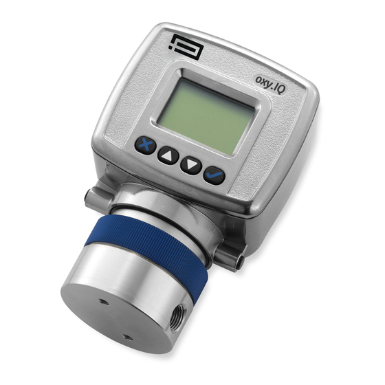
Chapter 1. Features and capabilities Introduction The oxy.IQ Panametrics oxygen transmitter (see figure 1 below) is a highly reliable and cost-effective two-wire, loop-powered transmitter with a linearized 4 to 20 mA output. It measures oxygen content in ten ppm ranges (10, 20, 50, 100, 200, 500, 1000, 2000, 5000 and 10000 ppm) and eight percentage ranges (1, 2, 5, 10, 21, 25, 50 and 100%). -
Page 10: Applications
Applications Sample systems Some typical applications for the oxy.IQ Panametrics In addition to the standard features and options, oxygen transmitter include the following: Panametrics offers a full line of sample handling systems for a variety of applications. If needed, Panametrics •... -
Page 11: Chapter 2. Installation
Chapter 2. Installation Mounting the oxy.IQ To install the oxy.IQ into the process or sample system, refer to figure 9 and/or figure 2 below and proceed to the next page. Connector 2.05 1.58 Note: All dimensions are inches [mm]. [52.1] [40.3] 2.75 [69.8]... -
Page 12: Wiring The Oxy.iq
2.2 Wiring the oxy.IQ To wire the oxy.IQ, refer to figure 14, then proceed as follows: 2. Connect the flying lead end of the cable as shown in the wiring diagram, according to one of the following conditions: WARNING! • No Zener barrier or galvanic isolator: For IS (intrinsically safe) applications, the –... -
Page 13: Installing An Oxygen Sensor
2.3 Installing an oxygen sensor To install a new or replacement oxygen sensor in the oxy.IQ, 7. Perform an air calibration on the new oxygen sensor refer to figure 6 below and complete the following steps: at this time. On the 0-25% oxygen scale, a properly calibrated oxygen sensor shows a reading of 20.9% on the display and generates a current of 17.4 mA at the 4-20 mA analog output terminals. -
Page 14: Chapter 3. Initial Setup And Operation
Chapter 3. Initial setup and operation The oxy.IQ display and keypad All programming of the oxy.IQ is done via the front panel keypad and display, as illustrated below. Display Down arrow Up arrow Cancel Enter Figure 7: oxy.IQ display and keypad The front panel components perform the following functions: •... -
Page 15: Adjusting And Calibrating The Oxy.iq
3.3 Adjusting and calibrating the oxy.IQ 3.3.2 Trimming the analog output Upon startup, the following five-step adjustment and calibration procedure must be performed on the oxy.IQ: To trim the analog output, calibrate the low (4 mA) end of 1. Select the desired output range. the output then the high (20 mA) end of the output. -
Page 16: Air Calibration
3.3.3 Air calibration 3.3.4 Span gas calibration An air calibration is always recommended upon installation Before beginning the span gas calibration, make sure the of a new oxygen sensor. However, because of the non- oxy.IQ is indicating an O level less than the span gas value, linearity of the oxygen sensor, a span gas calibration to ensure an accurate calibration. -
Page 17: Chapter 4. User Programming
Chapter 4. User programming Introduction IMPORTANT: The oxy.IQ service menu is for use by qualified service personnel only and requires a special passcode for access. That menu is not discussed in this chapter. This chapter provides instructions for programming all of the oxy.IQ menu options available to the user, which can be accessed without the use of a passcode. -
Page 18: The Display Menu
4.3 The display menu Proceed to the appropriate section to program the desired menu option. 4.3.1 Select the O parameter 4.3.3 Adjust the contrast To select the O parameter for display, complete the To adjust the display contrast, complete the following steps: following steps: 1. -
Page 19: The Output Menu
4.4 The output menu Proceed to the appropriate section to program the desired menu option. 4.4.1 Range 4.4.4 Error output See “selecting the output range.” To select the desired output value that will be sent to the analog output device upon an error, complete the following steps: 4.4.2 Trim 1. -
Page 20: Chapter 5. The Service Menu
Chapter 5. The service menu CAUTION! The service menu is intended for use by qualified service personnel only, and access to this menu requires entry of the service passcode. Misuse of the information in this menu may significantly impair the accuracy and performance of your oxy.IQ and may cause it to fail to meet its published specifications. -
Page 21: Chapter 6. Specifications
Chapter 6. Specifications Intrinsically safe (IS) installation Intrinsically safe installations require an MTL7706 Zener barrier, one IS cable, and one non-IS cable. Power requirements 24 to 28 VDC at 50 mA Cable P/N 704-1318-02 (2 m length) or p/n 704-1317-10 (10 m length) blue jacketed, twisted-pair with connector, 26 AWG conductors, with connector Output... -
Page 22: All Installations
6.3 All installations Process wetted materials Process connections SS process unit: 316 stainless steel, Viton® o-ring, 1/8” NPT-F inlet and outlet gold-plated sensor electrical contacts, and glass Dimensions User-selectable measurement ranges 4.10 x 2.75 x 2.05 in. (104.1 x 69.9 x 52.1 mm) •... -
Page 23: Appendix A. Outline And Installation Drawings
Appendix A. Outline and installation drawings This appendix includes the following oxy.IQ drawings: • Outline and installation (ref. dwg. 712-1840) • Cable, standard (ref. dwg. 704-1317, sh 1 of 2) • Cable, standard (ref. dwg. 704-1317, sh 2 of 2) •... - Page 24 Connector Notes: 1. Weight: 1.35 lb [612.3 g] 2. Color: metallic 3. Dimensions: inches [mm] 2.05 1.58 [52.1] [40.3] 2.75 [69.8] 4.10 [104.2] 0.32 1.33 [8.25] [33.9] 1.03 8-32 UNC-2B 1/8-27NPT-2B [26.27] .51 [12.9] max .27 [6.9] Ø .03 [.76] Ø...
- Page 25 Notes: 1. Cut cable to desired length according to length table shown. 2. Cut primaries & drain excluding brown & blue back to jacket as shown. 3. Strip & tin wires using lead free soder at end "b" , blue & brown, to a length of .250" as shown. End “B”...
- Page 26 Notes: 1. Interpet drawing in accordance with ASME Y14.5(M)-2009 2. Finished components to be ROHS compliant 3. Part to be clean of dirt/debris 4. Performance specification Rated current 2.0 A Rated voltage 24 VDC Operating temperature range -25 C TO 85 C Protection class meets NEMA type 1,3,4,6P and IEC IP67 Retention 6.75 lbs.
- Page 27 Hazardous location Non-hazardous location Power supply ZBB bus bar brown +24V green blue 24V return oxy.IQ transmitter MTL7706 IS ground 4-20MA analog IS cable 704-1318-xx input device (blue jacket) Non-IS cable 1. Equipment connected to barrier inputs must not use or generate more than 250V.
- Page 28 Hazardous or non-hazardous location Non-hazardous location Hazardous or non-hazardous location Class I, division 1, group ABCD Class I, division 2, group ABCD Class 1, zone 0, group IIC Non-hazardous location oxy.IQ oxy.IQ blue Loop-Power Device Loop terminal oxygen brown Note 4 blue Safety entity parameters: Associated...
-
Page 29: Appendix B. Menu Maps
Appendix B. Menu maps This appendix includes the oxy.IQ user menu maps (please note the service menu map is available to qualified Panametrics field service personnel only). - Page 30 Main menu Calibration Display Output Service Service Passcode Required Range ppm only Span value % only Trim Auto select Span gas 4 mA trim Display Range Flow span gas 20 mA trim Sensor life Error type Use days High O Contrast Low O Enter value...
- Page 31 Main Menu Calibration Display Output Service See User's Menu Map (no passcode required) Diagnostics Output mA Output % Temp °C Temp Res Gain OX-n (n=1-4) Sensor Type OX-1 OX-2 OX-3 OX-4 Figure 17: Service menu map...
- Page 32 [no content intended for this page]...
-
Page 33: Appendix C. Order String
Appendix C. Order string oxy.IQ BCD-E Model only oxy.IQ oxygen transmitter; 4 to 20 mA output Sensor No sensor Standard ppm, 0 to 10, 20, 50, 100, 200, 500, 1000 ppm Acid ppm, 0 to 10, 20, 50, 100, 200, 500, 1000 ppm Standard percent sensor Acid percent sensor Standard ppm, 0 to 100, 200, 500 and 1000 ppm... - Page 34 Appendix D. Panametrics oxy.IQ 1100 Technology Park Drive oxy.IQ safety manual Billerica, MA 01821 MODEL DWG NO. 714-1344 REV. C TITLE REL/ECO No. Drawn Date Checked Date Approved Date RN 7786 J. Ferro 1/8/15 1/8/15 J. Ferro 1/8/15 ECO-09423 CD SMART 1/19/16 CD SMART 1/19/16...
- Page 35 978 437 1000 inflammables ou combustibles, débrancher E-mail: Panametricstechsupport@bakerhughes.com l’alimentation avant l’entretien. Ireland AVERTISSEMENT Baker Hughes Sensing EMEA Free Zone East, Shannon, Remplacement des composants peut CO. CLARE, V14 V992, Ireland compromettre la sécurité intrinsèque. Tel: +35 361 470200 • Only trained, competent personnel may install, •...
- Page 36 Blue (+) Brown (-) Connection and wiring diagram The following diagram is the entity parameters for the oxy.IQ. Power connector Power requirements: Nominal operating parameters: 28VDC at 50mA...
- Page 37 EU DECLARATION CONFORMITY DOC-0046, Rev. C Panametrics 1100 Technology Park Drive Billerica, MA 01821 declare under our sole responsibility that the oxy.IQ™ Oxygen Transmitter to which this declaration relates, is in conformity with the following standards: • EN 60079-0:2012+A11:2013 • EN 60079-11:2012, II 1 G – Ex ia IIC T4 Ga QAN license 0795 : SGS Baseefa Ltd, Buxton SK17 9RZ, UK - NoBo# 1180 •...
- Page 38 Adjusting, oxy.IQ ..........7 Initial setup .
- Page 39 Display parameter, selecting ......23 Safety Order string ..........49 Auxiliary Equipment .
- Page 40 Tel: +1 978 437 1000 bakerhughes.com E-mail: Panametricstechsupport@ bakerhughes.com Panametrics, a Baker Hughes Business, provides solutions in the toughest applications and environments for moisture, oxygen, liquid and gas flow measurement. Experts in flare management, Panametrics technology also reduces flare emissions and optimizes performance.
Need help?
Do you have a question about the Panametrics oxy.IQ and is the answer not in the manual?
Questions and answers