Table of Contents
Advertisement
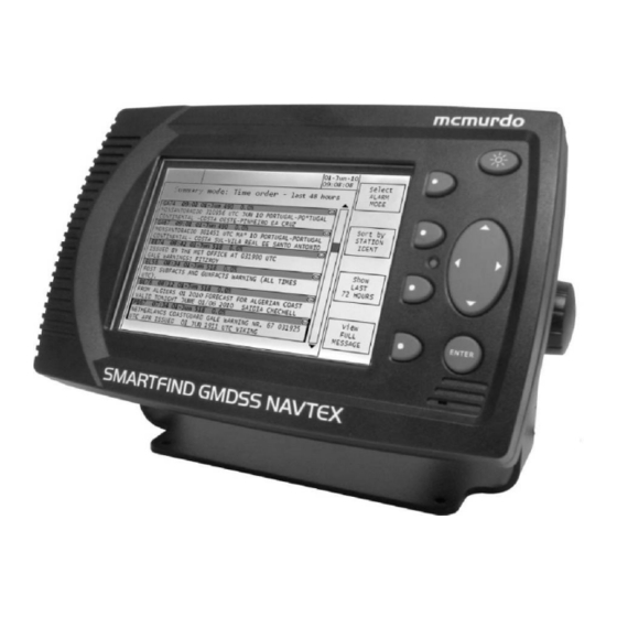
SMARTFIND GMDSS NAVTEX
USER & INSTALLATION MANUAL
GMDSS TRI-CHANNEL
NAVTEX RECEIVER
VESSEL IDENTIFICATION INFORMATION
Name
Call Sign
MMSI
SMARTFIND GMDSS
NAVTEX S/N
Antenna Type
RX frequencies
518 kHz
supported by antenna
490 kHz
4209.5 kHz
2015 Orolia Ltd
Part No: 93-204
Disclaimer
The information and illustrations contained in this publication are to the best of our
knowledge correct at the time of going to print. We reserve the right to change
specifications, equipment, installation and maintenance instructions without notice as
part of our policy of continuous product development and improvement. No part of this
publication may be reproduced, stored in a retrieval system or transmitted in any form,
electronic or otherwise without permission in writing from Orolia Ltd. No liability can be
accepted for any inaccuracies or omissions in the publication, although every care
has been taken to make it as complete and accurate as possible.
Advertisement
Table of Contents

Related Manuals for mcmurdo SMARTFIND GMDSS NAVTEX


Summary of Contents for mcmurdo SMARTFIND GMDSS NAVTEX
- Page 1 Disclaimer The information and illustrations contained in this publication are to the best of our SMARTFIND GMDSS NAVTEX knowledge correct at the time of going to print. We reserve the right to change specifications, equipment, installation and maintenance instructions without notice as part of our policy of continuous product development and improvement.
-
Page 2: Table Of Contents
Contents SAFETY NOTICES WARNING: Do not connect the SMARTFIND GMDSS NAVTEX main unit directly to an AC SAFETY NOTICES ................... 4 electrical supply, as an electric shock or fire hazard could result. QUICK START ....................5 ABOUT SMARTFIND GMDSS NAVTEX ............6 WARNING: Do not connect the SMARTFIND GMDSS NAVTEX system to a DC supply exceeding 31 V or reverse the supply polarity. -
Page 3: Quick Start
Set UTC time and date (automatic when connected to GNSS / GPS) tuned to 490 kHz, 518 kHz and 4209.5 kHz. The SMARTFIND GMDSS NAVTEX will receive on all three frequencies simultaneously in those parts of the world where ... -
Page 4: Introduction
NAVTEX is a method of transmitting navigational warnings and weather forecasts from designated coast radio stations. All English language transmissions are made on The SMARTFIND GMDSS NAVTEX has been designed to be easy to use with an the 518 kHz NAVTEX channel. Each NAVTEX station is allocated several time slots intuitive user interface and softkeys. -
Page 5: Operation
Display Icons The SMARTFIND GMDSS NAVTEX displays various icons in the status bar at the top of the display. SAR, warning alarm Unread message indicator The antenna or antenna cable is faulty The 518 kHz receiver is receiving The 490 kHz receiver is receiving The 4209.5 kHz receiver is receiving... - Page 6 'E', 'B' and 'C' (meteorological warnings). When a message with any of these message categories is received the SMARTFIND GMDSS NAVTEX operates select another its alarm relay contacts and transmits an NMEA "ALR" sentence to the currently message group selected alarm port.
-
Page 7: Setup Mode
Note that message pop-ups do not appear while in Setup mode to ensure they do not interrupt the editing of a configuration field. Always exit from Setup mode when you After the SMARTFIND GMDSS NAVTEX has been switched on for a while there will have finished configuring the SMARTFIND GMDSS NAVTEX and return to normal be a large number of NAVTEX messages stored in memory. - Page 8 No message on hand BROWN visible. Messages are selected for display by the SMARTFIND GMDSS NAVTEX’s software comparing the Station and Message Category information encoded into the message Message filters identifier (e.g. KA in the diagram above) with the filter settings entered by the user To enter setup mode, press and hold the ENTER key.
- Page 9 Setup mode: Receiver options installing and fault finding the SMARTFIND GMDSS NAVTEX. Each receiver has its own separate set of message filters; pressing the Select softkey cycles round the available receivers. The message XXXX kHz RECEIVER filter settings are all non-volatile and will be unchanged after a power cycle.
- Page 10 Use the Receive icon, Signal strength bar and Monitor window to help diagnose Demonstration – for use at exhibitions, etc installation problems and/or as a check that your SMARTFIND GMDSS NAVTEX is Time These parameters allow the time and date to be set manually in working correctly.
-
Page 11: System Alarms
Setup mode: Serial options alarm panel as well as actuating the SMARTFIND GMDSS NAVTEX’s remote alarm parameters for the two serial ports on the SMARTFIND GMDSS NAVTEX unit. The lower section of the display provides a monitoring facility for incoming messages on relay contacts. -
Page 12: Adjusting The Display
SMARTFIND GMDSS NAVTEX operates in a similar manner to a traditional ‘paper- ADJUSTING THE DISPLAY based’ NAVTEX receiver. LCD setup day & night modes However, in order to conserve paper, when the ‘Printer mode’ setting on the To enter LCD setup mode, press and hold the illumination key for 3 seconds the Setup mode : Serial options page is set to ‘On Demand’, the SMARTFIND... - Page 13 Trunnion mounting the display INSTALLATION The standard bulkhead mounting U-Bracket can be used to mount the SMARTFIND SMARTFIND GMDSS NAVTEX system overview GMDSS NAVTEX above or below a horizontal (or near horizontal) surface. For simplicity, power is shown diagrammatically throughout;...
- Page 14 Ship’s earth connection The earth terminal on the rear of the SMARTFIND GMDSS NAVTEX display must be connected to ship’s ground by the earth cable supplied. The earth connection should be kept as short as possible.
- Page 15 NAVTEX ONLY Signal cable connections As shown in the table above, the SMARTFIND GMDSS NAVTEX may be connected There is only one talker per twisted pair; there can be several listeners. The intention to different types of peripheral units including IBS & INS serial ports and printers.
- Page 16 Connection GMDSS Cable Colour Notes Number NAVTEX The red LED on the front panel of the SMARTFIND GMDSS NAVTEX mirrors the IBS_TXA WHITE/BLUE O/P to COM 1 or 2 function of the alarm relay. RED/BLUE Ship’s supply +ve...
-
Page 17: Antenna Installation
9-way D-type – COM 2 To receive on all frequencies the SMARTFIND GMDSS NAVTEX must be used with a wide frequency (400 kHz to 5 MHz) antenna that covers 518 kHz, 490 kHz and 4209.5 kHz. - Page 18 SMARTFIND GMDSS NAVTEX Minimum System Important NAVTEX antennas must be mounted clear of obstructions and at least 0.5 metres away from other antennas. Where practical avoid locating the NAVTEX antenna close to MF / HF transmitting antennas or VHF / AIS antennas.
- Page 19 Fitting the TNC connector A TNC connector is supplied as part of the SMARTFIND GMDSS NAVTEX Receiver Kit. Switch on the SMARTFIND GMDSS NAVTEX by applying power (12 V DC or 24 V DC) via a circuit breaker or fuse. ...
-
Page 20: Options
EXTERNAL RECEIVER Antenna fault icon appears at the top of the display: active antenna The SMARTFIND GMDSS NAVTEX has the capability to receive from an external Turn off the SMARTFIND GMDSS NAVTEX receiver (not supplied) on an additional NAVTEX frequency should such an additional frequency be mandated by the IMO in the future. - Page 21 Antenna Cable kit for ANA2, NMEA sentences supported Disconnect the antenna from the SMARTFIND GMDSS NAVTEX by unscrewing the (in priority order) RMC, GLL, ZDA for UTC and NRX, NRQ, TNC connector at the back of the SMARTFIND GMDSS NAVTEX.
-
Page 22: Navtex Stations List
Area Country Name Latitude Longitude Range (NM) NAVTEX STATIONS LIST Charleston 32°51’ N 79°57’ W Indonesia Jakarta 6°07’ S 106°52’ E North Korea Hamhung 39°50’ N 127°41’ E Chile Punta Arenas 53°10’ S 70°54’ W Azores Sao Miguel 37°49’ N 25°33’... - Page 23 Area Country Name Latitude Longitude Range (NM) Area Country Name Latitude Longitude Range (NM) Language Hawaii (USA) Honolulu 21°26’ N 158°09’ W North Korea Hamhung 39°50’ N 127°41’ E Netherlands Den Helder 52°06’ N 4°15’ E United Kingdom Portpatrick 54°51’ N 5°07’...
-
Page 24: End Of Life Statement
Web: www.mcmurdomarine.com Email: service.mcmurdo@orolia.com recommends that this product be disposed of in a sensible and considerate manner. For example, do not simply discard the product in the domestic waste. Instead take it to a civil recycling facility, or contact Orolia Ltd for advice. -
Page 25: Eu Declaration Of Conformity
EU DECLARATION OF CONFORMITY SOFTWARE REVISIONS Hereby Orolia Ltd declares that this NAVTEX is in compliance with the essential The NAVTEX is delivered with the software version according to the following table requirements and other relevant provisions of the Marine Equipment Directive (MED) which is to be filled in and maintained either by the manufacturer, distributor, dealer or –... - Page 26 “This page is intentionally blank” Orolia Ltd Silver Point Airport Service Road Portsmouth PO3 5PB United Kingdom Tel: +44 (0) 23 9262 3900 Fax: +44 (0) 23 9262 3998 www.mcmurdomarine.com Email: service.mcmurdo@orolia.com An Orolia Group Business 93-204 Issue 3...
Need help?
Do you have a question about the SMARTFIND GMDSS NAVTEX and is the answer not in the manual?
Questions and answers