
Related Manuals for Wave Central Axis Series

Summary of Contents for Wave Central Axis Series
- Page 1 Axis Series – TX User and Programming Guide ATXT1 AXTX1M – Mini AXTX1MB – Mini-B Wave Central LLC 99 Garden Parkway, Suite C., Carlisle, PA 17013 +1 888 736 9283 www.wave-central.com...
-
Page 2: Table Of Contents
Contents Contents__________________________________________________________ System Descriptions What are the Axis Series Transmitters? Applications Variants and Options Main Connectors Applicable Unit Software Placards and Markings General Exterior Placards and Marking System (AXTX1) Interior Placards and Marking System Exterior Color Schemes and Marking System... - Page 3 General Starting and Stopping – AXTX1 Working with the Control Panel – AXTX1 Advanced Operation General Encryption Control System General Connecting your PC to your Radio Configuring Basic Settings Configuring the Radio Understanding the Unit Information Tab Configuring the Modulation Parameters Configuring the Audio Parameters Configuring the Video Parameters Configuration Unit Parameters...
-
Page 4: System Descriptions
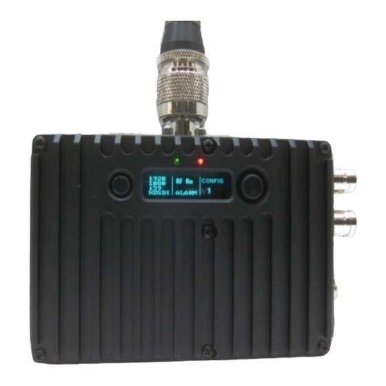
1. System Descriptions The subject equipment of this User Guide is identified as follows: Equipment Title Part Number Full Size Camera Back Transmitter AXTX1 Miniature Transmitter AXTX1M Miniature B Transmitter AXTX1MB Figure 1-1 – AXTX1: Camera Back Transmitter Figure 1-2a – AXTX1M - Mini Transmitter... -
Page 5: What Are The Axis Series Transmitters
Figure 1-3b – AXTX1MB: Mini-B Transmitter 1.1 What are the Axis Series Transmitters? The new Axis series transmitter comes in three different packages designed to suit the needs of many different types of applications. These transmitters both offer excellent coverage, low delay performance and multiple format/frame rate capabilities that enable users to acquire stunning images via a wireless connection, at extended non line of sight ranges. - Page 6 1.2 Features and Benefits It can be very useful to understand how the features of the unit yield tangible benefits to you. This table summarizes these features and, more importantly, the benefits. Features and Benefits Table Feature Benefit to you Digital COFDM Modulation.
-
Page 7: Applications
AXTX1M Mini about the size of an iPhone Digital Cinema and Video Assist applications AXTX1MB Mini-B Digital Cinema and Video Assist applications 1.3 Applications The Broadcast Transmitter has been designed to operate in multiple roles in many environments. Here are some examples: Professional Camera Back Applications –... -
Page 8: Variants And Options
1.3 Variants and Options 1.3.1 Variants – AXTX1 Camera Back Transmitter, with Camera Paint There are several major variants of the AXTX1 Camera Back Transmitter: Operating Frequency Band Model/Part Number AXTX1 CBT 1.990-2.492GHz 100mW AXTX1 - 2G AXTX1 CBT 5.730-5.840GHz 100mW AXTX1 - 5G AXTX1 CBT 6.436-7.120GHz 100mW AXTX1 - 7G... -
Page 9: Main Connectors
1.4 Main Connectors Here are the unit’s main connectors: 1.4.1 AXTX1 Broadcast Transmitter – Front View Figure 1-4 AXTX1 Front View Connectors Serial Item SMA Connector for 450MHz Camera Control Antenna. N Connector for AXTX1 Main RF Antenna. Tally Connector. - Page 10 XLR Connectors (x2) Analog Audio In. LEMO 4 pin female connector for CCU, camera paint system (RS-232) Hirose 6 pin female connector for CCU, camera paint system (RS-422) BNC Connector for HD/SDI Video Input. 1.4.2 AXTX1 Broadcast Transmitter - Bottom View Figure 1-5 AXTX1 Bottom Connectors Serial Item...
- Page 11 1.4.3 AXTX1 Broadcast Transmitter - Top View Figure 1-4 AXTX1 Top Connectors Serial Item DC Power NOT USED Type N Connector female, RF Output RF output Indicator SMA female connector for Paint System Antenna...
- Page 12 1.4.4 AXTX1 Broadcast Transmitter – Left Side View Figure 1-5 AXTX1 Left Side View Serial Item Transmitter Control Panel and Display Camera Mount Plate Camera/Transmitter Battery Mount Plate Transmitter/Paint Main DC Power Switch...
- Page 13 1.4.5 AXTX1 Broadcast Transmitter – Right Side View Figure 1-6 AXTX1 Right Side View Serial Item Camera Control Unit (CCU) Panel and Display for Paint Indicator, Paint Data connection with base station HDMI Type A input with embedded audio input and video input...
-
Page 14: Applicable Unit Software
1.5 Applicable Unit Software Each Transmitter has two software elements: Firmware that runs the device, via board level FPGA’s. (Field Programmable Gate Array) And Control Application that is run from a Windows based PC, external of the transmitter. 1.5.1 Internal Software Although much of the transmitter is built up of hardware components, many of the sophisticated features are implemented via firmware programmed into the FPGA’s. -
Page 15: Placards And Markings
2 . Placards and Markings Which model do I have? What is its Serial Number? The information covering placards, labels, markings, etc., showing the part number, legend and location of each placard, label, or marking required for safety or maintenance significant information. 2.1 General You’ll need to be able to quickly identify equipment types and serial numbers you have and at what frequencies your systems are designed to work. -
Page 16: Interior Placards And Marking System
2.4 Exterior Color Schemes and Marking System This system information includes specifications and requirements covering exterior color and related markings. 2.4.1 Enclosure Color The main enclosure is anodized in black. 2.4.2 Panel Markings The markings on the Axis Series are in white. -
Page 17: Cautions And Warnings
3 . Cautions and Warnings 3.1 Cautions and Warnings Serial Area Note Enclosures Do not remove any factory installed screws or fastenings. Damage to the units may result and void any warranties. Only authorised, trained personnel should open the product. There are no functions that required the user to gain access to the interior of the product. -
Page 18: Specific Absorption Rates (Sar) Fcc Exemption
Serial Area Note RF Emission When using this device please ensure a distance of 20cm is System maintained between your device and your body while the device is transmitting. Aircraft Safety Use of this equipment on board aircraft is strictly forbidden. Use of radio transmitter equipment in an aircraft can endanger navigation and other systems. -
Page 19: Panels, Displays, Alarm, Indicator And Controls
Each Axis-Series Broadcast Transmitter has several panels which contain all the interface connections for the units and the controls and indicators. There is an operational control panel on one panel of the unit. The next section describes the transmitter control panel for the all Axis Series Broadcast Transmitters. 4.2 Panel System – AXTX1... -
Page 20: Control Panel System - Axtx1Xx
4.5 Control Panel System – AXTX1 Series Transmitters Cancel/Back Joystick/Confirm Figure 2-3a AXTX1-Series TX Control Panel The control panel located on the right panel has two push buttons. Here’s what they do: 4.5.1 Joystick/Confirm Button (2) Button Does this… Joystick/Confirm Move the joystick for UP, DOWN, LEFT and RIGHT. -
Page 21: Connectivity
5 . Connectivity What are all the connectivity options? 5.1 General You’ll need a means of interconnecting equipment in the communication system for the purpose of transporting energy and /or communication signals. This section will help you identify all these wires, waveguides, glass-fibers, connecting elements, etc. -
Page 22: Control - Axtx1
5.3.3 Data The unit accepts Camera data signals through the DATA and PAINT interface on the front panel. The DATA is a LEMO 4-pin female connector; RS-232. The PAINT is a Hirose 6 female connector; RS-422 Your supplied Data cable assembly fits in here. A specific cable must be for the camera that will be control. -
Page 23: Setting Up Your Transmitter
6 . Setting up your Transmitter 6.1 General These guidelines will help you install and set up your system. As a general rule we connect in order: Antennas Signals Power 6.2 Connecting Antennas Each AXTX1 unit requires one antenna. The antenna must be fitted before the unit is placed into RF mode. -
Page 24: Connecting Power - Axtx1
1. Connect one BNC 2-way plug to the HD/SDI connector of the AXTX1. 2. Connect the other BNC 2-way plug to the video source. 3. Switch on the Video source. 4. Ensure the radio in configured to accept HD or SDI video. For a HDMI input you’ll need a Video source, AXTX1 and a HDMI cable suitable for the video source with a Type A plug at the other end. -
Page 25: A Look At The Display - Axta1
2. The other of the LEMO cable has a male XRL 4 pin plug that attaches to 12VDC power supply capable of at least 2 Amps 6.6.2 Connecting AC Power You’ll require a 12VDC Power Supply (optional) Adapter for 120VAC input and an AXTX1. 1. - Page 26 The control panel located on the right panel has two push buttons. Here’s what they do: 6.8.1 Joystick/Confirm Button (2) Button Does this… Joystick/Confirm Move the joystick for UP, DOWN, LEFT and RIGHT. Button Press the joystick for ENTER. 6.8.2 Cancel/Back Button (3) Button Does this…...
-
Page 27: A Look At The Menu Structure - Axtx1
6.9 A Look at the Menu Structure – AXTX1 6.9.1 Display Screen, Menu Structure... - Page 28 6.9.2 Display Screen, Menu Functions Menu Sub-Menu Function Unit Status Encoder/modulator board status. Unit Control RF output related settings and preset range modes. DVB-T Modulation options relevant to DVB-T mode. Video In Video input interface settings. Video Enc Video encoder options. Audio 1 Audio encoder 1 settings.
-
Page 29: Basic Operation
7 . Basic Operation 7.1 General This chapter covers normal day to day operations of a fully configured AXTX1 system. Once installed and configured the AXTX1 is easy to operate. These guidelines will help you perform basic operations on your Broadcast Transmitter. Note: If you are working with a new system or you need to change any of the configurations, look at the Advanced Operation and Control System chapters later in this guide. - Page 30 3. You’ll see the frequency and the Root menu on the display screen: Figure 7-1 Selecting the Root Menu 7.3.2 Selecting a Configuration You’ll need a powered AXTX1 set at the root menu as in 8-3-1 above. 1. Push up/down on the Joystick button to select a new configuration number Your new configuration appears highlighted.
- Page 31 3. Push the Joystick / Confirm button for two seconds to turn the RF off Figure 7-3 Selecting RF on or off 7.3.4 Using the Unit Status Menu You’ll need a powered AXTX1 set at the root menu as in 8-3-1 above. 1.
- Page 32 Vid Rate 8.522Mbps ASI Lock No or Yes S/W Ver Serial e03a095e Battery 12.0V May show Reply Error on Units where battery monitoring are not available. FPGA Ver 00023140 FPGA Temp Expect running internal temperature of 50-75°C depending on environment. Note: Don’t worry if you accidentally press the Joystick/Confirm button when you are moving about the Unit Status menu.
- Page 33 RF Power 100mW RF Atten 0.00dB 7.3.6 Using the Local Settings Menu You’ll need a powered AXTX1 set at the root menu as in 8-3-1 above. 1. Push Cancel / Back button 2. You’ll see the frequency and the Unit Status: menu on the display screen 3.
-
Page 34: Advanced Operation
8 . Advanced Operation 8.1 General These guidelines will help you perform advanced operations on your radio. 8.2 Encryption Your material is a valuable asset to your organization and naturally you don’t want others intercepting your radio signal. To do this, all that they need is a radio receiver that operates in the same mode and on the same frequency you are using to transmit. - Page 35 Figure 8-1 Switching on Transmitter Encryption 8.2.3 Number of Encryption Key Characters Required In our example above we used AES128 encryption. This needed a key of 32 characters. If we had chosen AES256 it would need a 64 character key which we spread over two fields like this: Figure 8-2 Write Encryption Key Dialog for AES256 key Type Key Type Number of Characters Needed...
- Page 36 Note: AES128 uses the same key entered as AES256 (lower). Therefore, setting one will overwrite the other. In the same way, Bcrypt uses the same keys as AES. ABS is entirely separate.
-
Page 37: Control System
9 . Control System 9.1 General To get the most from your radio system you must customize the programming for your operations and area. Use the Transmitter Control Application to navigate to the system setting you want to customize. CAUTION: Before you start programming your radio make sure the batteries are fresh and fully charged. If the radio loses power while you program it, its memory might be corrupted which will require you to reset defaults. - Page 38 9.2.4 Logging in to the Control Application You do not require a login to access the AXTX1 with the Control Application. 9.2.5 A Look at the Main Window Every Windows based application must have a main window as its entry point function. For the transmitter Control Application, this is the AXTX1 transmitter control window: Figure 9-1 Transmitter Control, Main Window Serial...
-
Page 39: Configuring Basic Settings
Configuration Set Buttons Connection Status Indicator RF Output Indicator Video Lock Indicator Encryption Button Refresh Button Apply Button Basic Setup Pane Presets (16 on this version) RS232/IP radio Buttons Toolbar 9.3 Configuring Basic Settings When you start-up the Control Application for the first time you’ll need to set up a couple of things to suit how you want to work with the software. - Page 40 3. Click the OK button 4. Click the Miscellaneous tab 5. In the Polling Interval Text box type a polling interval in milliseconds 6. Click the OK button 9.3.6 Understanding Connection Status This will show the green Connected caption when the application is connected to the unit. You’ll see the red Not Connected caption if the application and unit are disconnected.
- Page 41 4. The Select a file to save to dialog box will open. 5. Type a name for the config in the File name: text box. (Keep the .cfg extension). 6. Click the Save button. 9.3.9 Loading a Configuration 1. Click the Load Config from file button 2.
- Page 42 9.3.10 Opening the Advanced Options Window 1. Click the Advanced button. Note: I’ll tell you all about the advanced options in a later section. 9.3.11 Using the Configuration Set Buttons Used for saving or loading all sixteen configurations from a text file. When you have put some effort into setting up all your configuration tabs (Config 1 to Config 16) you’ll want to save them in one quick action.
- Page 43 4. Click the Open button. 5. The Please wait while the configs are read and sent… message box opens. 6. The Config Set loaded alert box opens. 7. Click the OK button. 9.3.14 Understanding the Connection Status Indicator Connection Status Indicator Means…...
- Page 44 Steady Red Aspect The unit is not emitting RF energy. 9.3.16 Understanding the Video Lock Indicator Video Lock Indicator shows… Means… Steady Green Aspect The unit has a locked video signal. Steady Red Aspect The unit has no video lock. 9.3.17 Using the Apply Button Each time you change any parameter on the Control Application it is...
- Page 45 9.3.19 Basic Setup Pane - Quick Setup There are several basic setup fields that enable you to do a quick setup of the unit without getting into fine details. (We’ll meet those later). There are the six basic things to setup: Basic Setting What you can do…...
- Page 46 Then, when you just have the simple two button panel available to you on the device, you’ll have maximum flexibility with settings. 9.3.21 Understanding the Toolbar Serial Toolbar Toolbar Button Button Engineering Opens the Engineering options window. There are no operational controls here.
-
Page 47: Configuring The Radio
9.4 Configuring the Radio Many of the configuration tasks are best achieved by using the Advanced Window. This is the Secondary window of the Control Application. This is where you can perform all the advanced setup. 9.4.1 Opening the Advanced Options Window To see the Advanced Options window: 1. -
Page 48: Configuring The Modulation Parameters
3. Select the Information tab The unit information fields are all greyed out. There is nothing for the operator to enter here; they are simply status results being sent back from the unit for your information. Unit Parameter Sample Entries Notes Video locked No or Yes... - Page 49 9.6 Configuring the Modulation Tab To work with the Modulation tab: 1. Click the Advanced button on the AXTX1 Transmitter Control Window 2. The Advanced options window opens 3. Select the Modulation tab The modulation tab can best be divided into three sections: Radio Settings DVB-T Settings Power Settings...
- Page 50 Modulation Off or On Switches the RF modulation on & off (same as the output RF button on the unit) Note: When you use the Basic Setup parameters on the Transmitter Control window, what you’re actually doing is pre-setting these parameters above. 9.6.2 Radio Settings Table The RF effect of preset transmit modes differ depending on a couple of other settings.
- Page 51 more error correction means a more robust signal and therefore more range. 7/8 means 7 bits out of 8 bits are data and therefore 1 bit is used for error correction. More user data means better picture quality, but less error correction means less robust signal and therefore less range.
-
Page 52: Configuring The Audio Parameters
Extra-long range 1 Extra-long range 2 Output power Low or High How much RF power you want the transmitter to emit. Presets: 10, 50, 100mW Output attenuation 0 is default If you have selected High Output power above high (dB) then the attenuation here will apply. -
Page 53: Configuring The Video Parameters
MPEG L1 48kHz stereo operational and bandwidth requirements. MPEG L1 48kHz mono As you select each of these audio modes and apply them, take a look at the Video bitrates MPEG L2 48kHz stereo parameter and watch it change. MPEG L2 48kHz mono The higher the audio quality used the less the video bandwidth available. - Page 54 9.8.1 Video Settings Unit Parameter Options Notes Video input You can select the video to be off or any available setting to suit the camera source Comp PAL you have. Comp NTSC Comp NTSC no pedestal Comp PAL S-Video Comp NTSC S-Video Comp NTSC S-Video no pedestal SDI PAL...
- Page 55 720p 59.94Hz Simply match the output of you camera to a setting from this list to ensure the 720p 60Hz transmitter passes your video signal 1080i 50Hz accurately. 1080i 59.94Hz 1080i 60Hz 1080p 23.976Hz 1080p 24Hz 1080p 25Hz 1080p 29.97Hz 1080p 30Hz 1080psf 23.976Hz 1080psf 24Hz...
-
Page 56: Configuration Unit Parameters
If you choose Full then you’ll see all 1080 lines, if you choose 1/2 you’ll see a down- sampled picture which requires much less bit-rate to encoder. Note: Using a sub-vertical resolution will force the Encoding mode to progressive. GOP Length Default GOP means Group of Pictures. - Page 57 A/V Sync Disabled Use as Total PTS No Checkmark For very advanced use only. Offset Checkmark This overrides automatic PTS delay calculations with the value entered in the DTS delay option. 9.9 Configuring the Unit Parameters To work with the Video tab: 1.
- Page 58 Sleep mode No or Yes Default is No. The unit can be forced into a sleep mode where main functions are disabled and the power consumption is significantly reduced. Select yes to put the unit into sleep mode. Select no to bring the unit back to normal operation.
- Page 59 PMT PID Default or Each table or elementary stream in a transport stream is identified by a 13-bit 0x0001 to 0x1FFE packet ID (PID). A demultiplexer extracts elementary streams from the transport stream in part by looking for packets identified by the same PID. In most applications, Time-division multiplexing will be used to decide how often a particular PID appears in the transport...
-
Page 60: Care And Maintenance
10 Care and Maintenance 10.1 General Do not subject the radio to physical abuse, excessive shock or vibration Do not drop, jar or throw the radio Do not carry the radio by the antenna Avoid exposure to excessive moisture or liquids Do not submerse the radio unless it is designed to be submersible Do not expose the radio to corrosives, solvents, cleaners or mineral spirits Avoid exposure to excessive cold and heat... -
Page 61: Appendix A-Glossary
11 Appendix A-Glossary 11.1 General The glossary contains some abbreviations and terms you’ll need to know. 11.2 Glossary Means… Alternating Current. Current that is continually changing in magnitude and periodically in direction from a zero reference level. In cryptography, the Advanced Encryption Standard (AES) is an encryption standard adopted by the U.S. - Page 62 Means… Asynchronous Serial Interface. A streaming data interface which often carries an MPEG Transport Stream. An ASI signal can carry one or multiple SD, HD or audio programs that are already compressed, not like an uncompressed SD-SDI (270Mbs) or HD-SDI (1.45Gbs). An ASI signal can carry varying amounts of data but is always padded to run at a fixed line rate of 270 Mb/s.
- Page 63 from a camera to digital data. Means… Forward Error Correction is a system of error control for data transmission, whereby the sender adds redundant data to its messages, also known as an error-correction code. This allows the receiver to detect and correct errors (within some bound) without the need to ask the sender for additional data.
- Page 64 Infra-Red - Infrared (IR) radiation is electromagnetic radiation whose wavelength is longer than that of visible light. Impedance The total opposition offered by a circuit or component to the flow of alternating current. Means… LOS and NLOS Line-of-sight propagation refers to electro-magnetic radiation including light emissions travelling in a straight line.
- Page 65 Pan, Tilt and Zoom – PTZ is a common way of referring to controllable cameras. Propagation A phenomenon by which any wave moves from one point to another; the travel of electromagnetic waves through space or along a transmission line. Means…...
- Page 66 WAVE CENTERAL LLC, IS NOT LIABLE FOR DAMAGES TO THIS OR ASSOCIATED EQUIPMENT CAUSED BY ANY ERRORS OR OMMISSIONS CONTAINED HEREIN. IF YOU HAVE QUESTIONS REGARDING THIS MANUAL CONTACT: Wave Central LLC 99 Garden Parkway, Suite C., Carlisle, PA 17013 +1 888 736 9283 www.wave-central.com...
Need help?
Do you have a question about the Axis Series and is the answer not in the manual?
Questions and answers