Advertisement
Available languages
Available languages
Quick Links
M3
HUMIDISTAT
INSTALLER:
PLEASE FILL OUT AND MAIL WARRANTY CARD AFTER INSTALLATION
IS COMPLETE. LEAVE OWNERS MANUAL WITH HOME OWNER.
I. SAFETY
WARNING! Improper electrical wiring can result in fire or loss of humidity
control. Disconnect electrical power before installing and servicing. Failure to
disconnect electrical power may result in injury or death. All local building
and electrical codes must be followed.
The M3 must be installed by a qualified Technician. Failure to properly install
the M3 may result in property damage or personal injury.
Homeowners must read instructions and understand the operation of the M3
and the humidifier(s) it controls.
Improper operation can result in over or under humidification.
humidification can result in condensation, structural damage and mold.
Condensation within a building's structure can cause loss of structural
strength. Condensation can also enable mold and mildew growth resulting in
personal injury and damage to building structure and contents.
Safety questions regarding the 3may be directed to General Filters, Inc.
II. APPLICATION
The M3 humidistat provides low voltage control of humidifiers installed in
central heating systems. The humidistat has a SPST switch and is designed
for wall mounting in the living area, or mounting on the return air duct.
RANGE: 10% to 60% RH ELECTRICAL RATING: 30 VAC / 60 VA
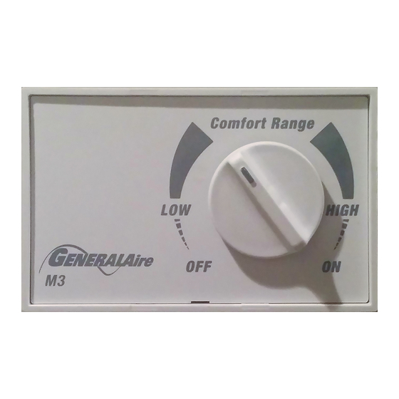
OPERATION
Set the control knob within the Comfort
Range setting. Comfort Range is the
recommended setting for optimum
whole-house humidification at 30% to
50%. The Low setting is at 10%
whereas the High setting is at 60%.
Setting the humidistat above or below
the Comfort Range may not provide
satisfactory results for your home.
III. INSTALLATION INSTRUCTIONS
PRECAUTIONS
The installer must be a qualified Technician. Disconnect electrical power
before beginning installation. Do not install the humidistat on the warm air
duct. The foam gasket is used for mounting on a return duct only. Conduct a
thorough checkout before leaving the installation.
WALL MOUNTING INSTRUCTIONS
1. Chose a location for the M3 about five feet above the floor on an inside
wall with average room temperature and humidity conditions.
2. Drill a small hole in the wall and run low voltage wiring to the location
chosen. Pull about 6" of wire through the hole. Plug the opening to
prevent drafts from affecting the humidistat operation.
3. Remove the housing from the base by prying with a small screwdriver at
the notch in the side of the housing.
4. Mount the base horizontally over the wires using level. Attach directly to
the wall, using four screws provided.
5. Connect wires to screw terminals on the control assembly as shown in
DIAGRAM 1, 2, 3, 4 or 5. Replace housing.
Over
RECOMMENDED
OUTDOOR
SETTING
TEMPERATURE
-30ϒ F -35ϒ C
10%
-10ϒ F -23ϒ C
20%
0ϒ F -18ϒ C
25%
+10ϒ F -12ϒ C
30%
+30ϒ F - 1ϒ C
40%
+40ϒ F + 4ϒ C
50%
OWNERS MANUAL
R
MOUNTING ON THE RETURN AIR DUCT
Do not install the humidistat on the warm air duct.
1. Locate the humidistat at least 24" upstream of the humidifier or bypass on
the return air duct. Avoid areas of direct radiation like secondary heat
exchangers in the fan compartment.
2. Place template using level. Cut sensor hole as shown on template. Drill
four 3/32" holes as shown.
3. Remove the housing from the base by prying with a small screwdriver at
the notch in the side of the housing.
4. Place the outer part of the foam gasket on the humidistat base and mount
the base with four screws. Low voltage wire may enter the humidistat
under the foam seal.
5. Connect wires to screw terminals on the control assembly as shown in
DIAGRAM 1, 2, 3, 4 or 5. Replace housing.
WIRING
WARNING! Disconnect electrical power before beginning installation. 120
volts may cause injury or even death.
Refer to wiring DIAGRAM 1, DIAGRAM 2, DIAGRAM 3, DIAGRAM 4 or
DIAGRAM 5.
ALL WIRING SHOULD COMPLY WITH LOCAL ELECTRICAL CODES.
CHECKOUT
With furnace in operation, turn humidistat to "ON" position. Observe
humidifier operation.
SETTINGS
WARNING! Do not set relative humidity too high during cold weather. Over
humidification can result in condensation, structural damage and mold.
Condensation within a building's structure can cause loss of structural
strength. Condensation can also enable mold and mildew growth resulting in
personal injury and damage to building structure and contents.
Refer to OPERATION for proper settings.
DIAGRAM 1
WIRING 24V. BYPASS HUMIDIFIER
ON-OFF
SWITCH
L 1
115v.
(H O T )
60CY.
L 2
HUMIDIFIER 24V.
SOLENOID VALVE
OR 24V. DRUM MOTOR
DIAGRAM 2
WIRING 120V. BYPASS HUMIDIFIER
HUMIDISTAT
FIELD SUPPLIED
RELAY 24 V. COIL
N.O. 5A MIN.
727-58
24 V. TRANSFORMER
120V.
(20-30 volts A.C.)
(OMIT IF POWER SUPPLY
IS SWITCHED WITH
FURNACE CYCLE)
12500 AIR
(OMIT IF POWER SUPPLY
PRESSURE
IS SWITCHED WITH
SWITCH
FURNACE CYCLE)
NO
C
HUMIDISTAT
727-58
24 V. TRANSFORMER
(OMIT IF POWER SUPPLY IS 20-30 VAC)
HUMIDIFIER 120V.
SOLENOID VALVE
OR 120V. DRUM MOTOR
L 2
N O
L 1
C
(HOT)
ON-OFF
12500 AIR
PRESSURE
SWITCH
SWITCH
115v.
60CY.
Advertisement

Related Manuals for GeneralAire M3


Summary of Contents for GeneralAire M3
- Page 1 FIELD SUPPLIED RELAY 24 V. COIL WALL MOUNTING INSTRUCTIONS N.O. 5A MIN. 1. Chose a location for the M3 about five feet above the floor on an inside HUMIDIFIER 120V. SOLENOID VALVE wall with average room temperature and humidity conditions.
- Page 2 39 CROCKFORD BLVD. Nom du marchand: NOVI, MICHIGAN 48375-1115 SCARBOROUGH, ONTARIO M1R3B7 STREET ADDRESS WWW.GENERALAIRE.COM WWW.CGFPRODUCTS.COM Adresse: STATE CITY POSTAL CODE Province: Ville: Code postal: DATE OF INSTALLATION / DATE DE INSTALLATION Litho in U.S.A. FORM NO. M3-07 (FILE 13143)
- Page 3 DIRECTIVES POUR FIXER L'APPAREIL AU MUR 1. Choisissez un emplacement pour le M3 sur une paroi intérieure qui se trouve au moins cinq pieds au dessus du sol, et où règne une température et un taux d'humidité relative moyenne par rapport aux conditions dans la salle.
- Page 4 +VR SET GND AB GENERAL FILTERS, INC. CANADIAN GENERAL FILTERS, LTD . 43800 GRAND RIVER AVE. 39 CROCKFORD BLVD. NOVI, MICHIGAN 48375-1115 SCARBOROUGH (ONTARIO) M1R3B7 WWW.GENERALAIRE.COM WWW.CGFPRODUCTS.COM CAVALIER INSTALLÉ EN USINE HUMIDISTAT Lithographie faite aux États-Unis FORMULAIRE Nº M3-07 (DOSSIER 13143)
Need help?
Do you have a question about the M3 and is the answer not in the manual?
Questions and answers
is there a filter inside?