
Related Manuals for Banner R-GAGE T30R


Summary of Contents for Banner R-GAGE T30R
- Page 1 ® R-GAGE T30R Sensor Instruction Manual Original Instructions 217048 Rev. C 17 June 2021 © Banner Engineering Corp. All rights reserved 217048...
-
Page 2: Table Of Contents
......................................28 8.2 Cordsets ......................................28 8.3 Configuration Tool ..................................29 9 Product Support and Maintenance ........................... 30 9.1 Repairs ......................................30 9.2 Contact Us ..................................... 30 9.3 Banner Engineering Corp. Software Copyright Notice ........................30 9.4 Banner Engineering Corp. Limited Warranty ..........................30... -
Page 3: Product Description
FMCW radar detects moving and stationary objects • Adjustable sensing field—ignores objects beyond setpoint • Easy setup and configuration of range, sensitivity, and output using the Banner Radar Configuration Software • Sensing functions are immune to wind, fog, steam, and temperature changes and resistant to rain and snow •... -
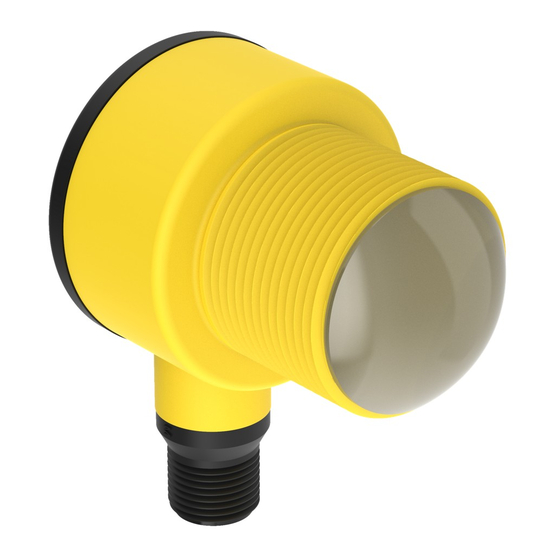
Page 4: Features And Indicators
® R-GAGE T30R Sensor specific distance, ignoring objects beyond this distance (background suppression). Or the sensor can be taught a reference point to detect the presence or absence of an objects (retroreflective). Figure 1. Sensing Range Sensing Range Measurement Reference Point Reliable detection and Detection Reliable... -
Page 5: Installation Instructions
5. Check the device alignment, aiming it near parallel to, or down towards, the ground. If aiming at a target, alignment and signal strength can be checked via the red Signal Strength LED or the Banner Radar Configuration Software. -
Page 6: Connect To The Sensor
5 = Gray (Connect for use with remote input or Banner Radar Configuration software) Load D2_Out Input * Push-Pull output. User-configurable PNP/NPN setting. 2.5 Install the Software Important: Administrative rights are required to install the Banner Radar Configuration software. www.bannerengineering.com - Tel: + 1 888 373 6767... - Page 7 2. Navigate to and open the downloaded file. 3. Click Install to begin the installation process. 4. Depending on your system settings, a popup window may appear prompting to allow Banner Radar Configuration to make changes to your computer. Click Yes.
-
Page 8: Getting Started
7. Click Connect. The Connection screen closes and the sensor data displays. 3.2 Software Overview Easy setup and configuration of range, sensitivity, and output using the Banner Radar Configuration and Pro Converter Cable. Figure 4. Banner Radar Configuration Software 1. Navigation toolbar—Use this toolbar to connect to the sensor, to save or load a configuration, or to reset to factory defaults 2. -
Page 9: Banner Radar Configuration Workspace
Save a configuration to a desired location for future use. Reset Frequently Used Settings Resets the software settings without changing the configuration of the attached sensor. Exit Exit the Banner Radar Configuration Software. From the Sensor menu, the following options are available: Connect Connect to the sensor. -
Page 10: Summary Pane
® R-GAGE T30R Sensor Hysteresis Lines Displays the hysteresis distance. 4.3 Summary Pane The Summary pane (blue shaded area) displays Distance, Signal Strength, and Output Status. Distance Displays the distance to the target. Signal Strength Displays the amount of excess gain of the signal received from the target. The excess gain is relative to the minimum detection threshold (Signal Strength Threshold = 1). -
Page 11: Analog Tab
® R-GAGE T30R Sensor 4.4.2 Analog Tab The following are the parameters on the Analog tab on the Sensor Settings pane. This tab is available for analog models. Analog Span Define the outer limits of the analog range. This can be used to create a positive or negative slope. Analog output options: Current: 4 mA to 20 mA Voltage: 0 V to 10 V or 0.5 V to 4.5 V... -
Page 12: Discrete 1 Tab
Window: Define two setpoints to create window limits. Complementary: Output 2 will be opposite of Output 1. Pulse Pro/PFM: Pulse Pro/PFM output to interface with Banner lights or a PLC with PFM inputs. Distance Settings Available when Output Mode is set to Switch Point or Window. -
Page 13: Live Sensor Data Controls
An output of 50 Hz or 650 Hz (user defined in the software) represents a loss of signal condition where there is no target or the target is out of range. This output can be tied directly to a number of Banner lights for visual feedback without the need for a controller. -
Page 14: Configuring A Sensor
IO-Link Master requires. Each IO-Link Master AOI is customized for a given brand of IO-Link Master. Add and configure the relevant Banner IO-Link Master AOI in your ladder logic program first; then add and configure Banner IO-Link Device AOIs as desired, linking them to the Master AOI as shown in the relevant AOI documentation. -
Page 15: Remote Input
(0 V DC). The remote input wire is disabled by default. Pulse the remote input wire 10 times or use the Banner Radar Configuration software to enable the feature. After enabling the remote input feature, pulse the remote input according to the diagram and the instructions provided in this manual. - Page 16 Reset to Factory Defaults Enable/Disable Remote Teach Note: If a factory reset is performed through the Banner Radar Configuration Software, the remote input wire becomes disabled (factory default setting). If the sensor is returned to factory defaults by using the remote input wire, the input wire remains enabled and the rest of the settings are restored to factory defaults.
-
Page 17: Remote Teach
® R-GAGE T30R Sensor 5.4.1 Remote Teach Use the following procedure to teach the first and second switch points. 1. Pulse the remote input once. The green Power LED flashes, the yellow LED is off, and the red LED is off. 2. - Page 18 ® R-GAGE T30R Sensor Set the Sensitivity Use Sensitivity Selection to set the signal strength threshold. 1. Access Sensitivity Selection. Action Result Triple-pulse the remote input. The green power LED flashes slowly. 2. Select the desired signal threshold. Action Result Pulses TEACH Mode Signal Strength Threshold = 1...
-
Page 19: Reset The Sensor To Factory Defaults
Reset the sensor to factory default settings using one of two methods. Note: If a factory reset is performed through the Banner Radar Configuration Software, the remote input wire becomes disabled (factory default setting). If the sensor is returned to factory defaults by using the remote input wire, the input wire remains enabled and the rest of the settings are restored to factory defaults. -
Page 20: Factory Default Settings
® R-GAGE T30R Sensor 5.5.1 Factory Default Settings Table 4: General Tab Default Settings Setting Factory Default Response Speed Medium Signal Strength Threshold Target Mode Nearest Target Measurement Hold Disabled Discrete Output & Remote Input Remote Input Wire Disabled Push Buttons Enabled Table 5: Analog Tab Default Settings Setting... -
Page 21: Using Measurement Hold Example
® R-GAGE T30R Sensor 5.6 Using Measurement Hold Example Figure 11. Measurement Hold Raw Measurement Output Measurement Maximum Distance Decrease 1 sec 1 sec Maximum Distance Increase <1 sec Time (s) The Hold Time is set to 1 second. The Max Distance Change threshold (red lines) adapts based on the previous Raw Measurement sample (blue lines) as long as that sample was within the previous thresholds. -
Page 22: Specifications
® R-GAGE T30R Sensor 6 Specifications Range Repeatability The sensor can detect an object at the following ranges, depending on < 1 mm the material of the target: Maximum Output Power T30R-1515 models: EIRP: 100 mW, 20 dBm Detection Range: 0.15 m to 15 m (0.5 ft to 49.2 ft) Output Protection Measurement Range: 0.3 m to 15 m (1.0 ft to 49.2 ft) Protected against output short-circuit... -
Page 23: Fcc Part 15 And Can Ices-3 (B)/Nmb-3(B)
Connect the equipment into an outlet on a circuit different from that to which the receiver is connected. • Consult the manufacturer. Note: Changes or modifications made to this equipment not expressly approved by Banner Engineering Corporation may void the FCC authorization to operate this equipment. 6.2 Industry Canada IC ID: 7044A-T30R—This device complies with Industry Canada license-exempt RSS standard(s). -
Page 24: Pc Requirements
.NET Hard Drive Space USB Port 500 MB Available USB port Important: Administrative rights are required to install the Banner Radar Configuration software. 6.4 Dimensions All measurements are listed in millimeters [inches], unless noted otherwise. T30R-1515 Models Integral QD Models... -
Page 25: Beam Patterns
® R-GAGE T30R Sensor 6.5 Beam Patterns The beam pattern of the radar sensor is dependent on the radar cross section (RCS) of the target. The beam pattern graphs are guides for representative object detection capabilities based on different sized radar cross sections and corresponding example real world targets. - Page 26 ® R-GAGE T30R Sensor Figure 15. Typical beam pattern, in degrees, of T30R-4545 on Figure 16. Typical Beam pattern, in meters, of T30R-4545 with fixed target representative targets and various Signal Strength Thresholds Passenger Train (Radar cross section = 6000 m 2 ) Car (Radar cross section = 6 m 2 ) Reference Target: Car (Radar Weak Object (Radar cross section = 1 m 2 )
-
Page 27: Update The Software
1, above, to update the Software. 3. Navigate to and open the file BannerRadarConfigInstaller.exe. 4. Depending on your system settings, a popup window may appear prompting to allow Banner Radar Configuration Software to make changes to your computer. Click Yes. -
Page 28: Accessories
® R-GAGE T30R Sensor 8 Accessories 8.1 Brackets All measurements are in mm SMB30A SMB1815SF • Right-angle bracket with • Swivel with set screws curved slot for versatile for mounting sensors by orientation the cable hub • Clearance for M6 (¼ in) •... -
Page 29: Configuration Tool
Note: The splitter in the PRO-KIT has two male and one female connectors. The CSB-M1251M1251B splitter has one male and two female connectors. Use the CSB-M1251M1251B to connect the sensor to power and a one of the Banner Pro lights with the Pulse Pro output. 8.3 Configuration Tool... -
Page 30: Product Support And Maintenance
This software is protected by copyright, trade secret, and other intellectual property laws. You are only granted the right to use the software and only for the purposes described by Banner. Banner reserves all other rights in this software. For so long as you have obtained an authorized copy of this software directly from Banner, Banner grants you a limited, nonexclusive, nontransferable right and license to use this software. - Page 31 Index maximum distance decrease 10 sensor polarity 10 maximum distance increase 10 Sensor Settings 10–12 advanced target 10 measurement hold 10 signal 9 analog tab 11 minimum active sensing range 10 signal strength 10 analog window 9 signal threshold 9 averaging 11 software 14, 27 switch point 12...
Need help?
Do you have a question about the R-GAGE T30R and is the answer not in the manual?
Questions and answers