
Related Manuals for Apollo AIM-1SL

Summary of Contents for Apollo AIM-1SL
- Page 1 AIM-1SL & AIM-2SL Hardware Manual Revision Date: 19 OCT 2011 This manual contains confidential information and may only be reproduced or distributed with the written consent of Apollo Security Sales, Inc. © 2011 Apollo Security Inc.
- Page 2 Apollo Security, Inc. While every precaution has been taken in the preparation of this document, Apollo Security assumes no responsibility for errors or omissions, or for damages resulting from the use of information contained in this document or from the use of programs and source code that may accompany it.
- Page 3 IMPORTANT INFORMATION W A R N I N G HIGH VOLTAGE, AC MAIN POWER SHOULD ONLY BE CONNECTED BY QUALIFIED, LICENSED ELECTRICIANS. ALL APPLICABLE LAWS AND CODES MUST BE FOLLOWED. IF THIS PRECAUTION IS NOT OBSERVED, PERSONAL INJURY OR DEATH COULD OCCUR Power should not be applied to the system until after the installation has been completed.
-
Page 4: Table Of Contents
AIM-1SL & AIM-2SL Hardware Manual Table of Contents Part I Introduction 1 Overview ........................... 2 2 General Features ........................... 2 3 Modes Of Operation ........................... 3 Part II Hardware Layout 1 Terminal Connectors ........................... 6 2 DIP Switches ........................... 8 DIP Switch Tables ................................. - Page 5 ........................... 33 2 Reader / Keypad ........................... 34 3 Input Zones ........................... 34 4 Output relays ........................... 34 Part V Specifications Part VI Supplemental Figures Part VII Table of Figures Part VIII Revision History Index © 2011 Apollo Security Inc.
-
Page 6: Part I Introduction
Part Introduction... -
Page 7: Overview
7000 events allows the AIM-1/2SL to work independently after initial programming. The AIM-1SL supports two readers that control the single onboard door strike relay. A successful access grant on either reader will open the strike relay--this is known as 'Paired Mode'. Exit push button, door contact and two auxiliary inputs are provided. -
Page 8: Modes Of Operation
Facility Code downloaded from the AAN/AAM controller, access is granted. PAIRED / UNPAIRED MODE (1 or 2 Door Control) The AIM-1SL always works in paired mode. A successful card read on either reader will energize the single onboard strike relay. - Page 9 Part Hardware Layout...
-
Page 10: Part Ii Hardware Layout
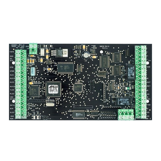
AIM-1SL & AIM-2SL Hardware Manual Hardware Layout Figure 2.1 AIM-1/2SL Diagram. Terminal connectors, DIP switch, output relays, device port driver connection, and other component locations are shown. © 2011 Apollo Security Inc. -
Page 11: Terminal Connectors
DATA1 TB4-6 Buzzer Control TB4-7 Green LED Control GLED TB4-8 Reader Power Ground TB3-5 Signal Ground TB3-4 Receive Data (-) TB3-3 Receive Data (+) Serial Communication Connection TB3-2 Transmit Data (-) TB3-1 Transmit Data (+) © 2011 Apollo Security Inc. - Page 12 AIM-1SL & AIM-2SL Hardware Manual AIM-1/2SL Terminal Connections TB7-4 Diode Internal Suppression Diode Connection DIODE Strike Relay 1 TB7-3 Normally Open TB7-2 Normally Closed Door 1 Strike Relay Connection TB7-1 Common TB2-2 20mA Loop Signal Out DSOUT ADA 10/11 External Relay Loop...
-
Page 13: Dip Switches
DIP switch settings as any changes will not take effect unless the power is cycled. 2.2.1 DIP Switch Tables Communications Address (SW1) Baud Rate Input Monitor Mode 1200 Unsupervised 2400 Supervised 4800 9600 Table 2.2: AIM-1/2SL DIP Switch Settings © 2011 Apollo Security Inc. -
Page 14: Dip Switch Function
AIM-1SL & AIM-2SL Hardware Manual 2.2.2 DIP Switch Function Communications Address —Sets the address that identifies the device on the communications line. This number must be unique for each device on a single RS-485 communications line. In most systems, this address will correspond to Reader 1 and the following addresses on the serial line will be reserved for Readers 2 which uses this ‘virtual’... -
Page 15: Normal Operation
For normal operation it is not necessary to update the firmware. If this becomes necessary, contact your Apollo Support Representative. Firmware updating should only be done under the recommendation and guidance of your Apollo technical support representative. -
Page 16: Additional Installation Information
AIM-1SL & AIM-2SL Hardware Manual Additional Installation Information 2.7.1 Mounting Holes Four holes are provided for mounting the AIM-1/2SL. Standoffs should be used when mounting in order to protect the underside of the circuit board. Figure 2.7.1 AIM-1/2SL Mounting Holes. - Page 17 Part System Wiring...
-
Page 18: Part Iii System Wiring
Grounding the reader provides a good shield against external transients. There are three types of circuit grounds in systems using Apollo products: DC ground, RS-485 signal ground, and Safety (Earth) ground. -
Page 19: Safety (Earth) Ground
Please check the applicable regulations and legislation in your country prior to installing the AIM-1/2SL controller and other Apollo products. In the US, the National Electrical Code, as well as other safety regulations, require that all equipment chassis and/or enclosures be grounded in order to prevent electrical shock hazards. -
Page 20: Rs-485 Communications Line
AIM-1SL & AIM-2SL Hardware Manual RS-485 Communications Line The typical connection for field devices (such as the AIM-1/2SL) on a device port with an Apollo AAN/AAM controller is through an RS-485 serial communication line. First, for communication to be possible, the device port must have a communications driver installed in the corresponding socket (see Part 2.3). - Page 21 CORRECT CORRECT INCORRECT INCORRECT Figure 3.4.1.1 RS-485 Bus Configuration. The RS-485 communication line must be laid out in a daisy-chain wiring pattern. Avoid wiring devices in a ‘star’ configuration to avoid reflections and termination problems. © 2011 Apollo Security Inc.
-
Page 22: Card Reader Wiring
AIM-1SL & AIM-2SL Hardware Manual Figure 3.4.1.2 RS-485 Device Connections. The AAN-100 serves as the master on the line and the field devices are slaves. The receive lines of the master are wired to the transmit lines of the slaves, and the receive lines of the slaves are wired to the transmit of the master. - Page 23 Refer to the Terminal Connectors table and the installation instructions for the reader that will be used for exact wiring positions. © 2011 Apollo Security Inc.
-
Page 24: Reader Input Wiring
AIM-1SL & AIM-2SL Hardware Manual Reader Input Wiring The AIM-1/2SL has four input circuits which have different functions according to the mode used (Paired or Unpaired). These inputs can be configured as UL Grade “B” (unsupervised) or UL Grade “A” (supervised). -
Page 25: Door Contact Input (Door Position Switch)
Strike Time will always be very short (the reader thinks the people are opening the door quickly), resulting in it being impossible to open the door. © 2011 Apollo Security Inc. -
Page 26: Exit Pushbutton Input (Request To Exit, Rex)
AIM-1SL & AIM-2SL Hardware Manual 3.6.3 Exit Pushbutton Input (Request To Exit, REX) The Exit Pushbutton input will be disabled during Reader Tamper and for 1 minute after tamper condition ends! Terminal Connectors: EPB, EPBR; AUX2, AUX2R (In Unpaired Mode) (See Table 2.1 ) The Exit Pushbutton input is used by the reader to inform the reader of a door opening without first using the card / PIN. -
Page 27: Strike Wiring, General
A typical electric door lock (strike) will require approximately 250 mA. (.250 amps) to control. The relay contacts on all Apollo relays are capable of switching up to 24 volts DC at up to 2 amps. If the particular locking device requires more that 2 amps to control, a separate, external relay capable of switching the required amount of current must be installed. -
Page 28: Strike Wiring, Internal Relay
AIM-1SL & AIM-2SL Hardware Manual The most common method of suppression used on DC power strikes is installation of a reverse biased diode as close a possible to the strike itself. Any type of general purpose diode (1N4001 – 1N4006, etc.) will work. - Page 29 Common "C" Strike Normally Open "NO" Figure 3.7.3.1 Strike Wiring Diagram - Fail Secure. A wiring example for Fail Secure wiring. Refer to Table 2.1 for exact locations of strike relay connections for the AIM-1/2SL © 2011 Apollo Security Inc.
- Page 30 AIM-1SL & AIM-2SL Hardware Manual The diagram below illustrates connection of a DC powered, Fail-Safe, door strike. This type of strike requires power to hold the door closed. The power will be supplied through the normally closed (NC) relay contact of the strike relay.
-
Page 31: Ada External High Security Relays
DC Powered Door Strike. The strike is wired Fail-Secure, thus power is supplied to the strike only when the relay is activated. The ADA-10 is wired in a similar fashion but instead of wiring to terminals, wiring must be connected to the special connector of the ADA-10. © 2011 Apollo Security Inc. -
Page 32: Strike Wiring, External Ada-10/11, High Security Relay
The ADA-10 module is a potted module with an 8 position connector on the end of a short ribbon cable. Optional connectors and mounting tools (ATL-10, 490-040) may be purchased from Apollo The ADA-10 has several jumpers on the top surface that must be cut to configure the operation of the relay. -
Page 33: Additional Output Relay Wiring
3.7.4.3 ADA DIP Switches/Jumpers In order for ADA-10 and ADA-11 devices to operate properly, The the corresponding Jumpers or DIP switches must be set in order to define the purpose the ADA will serve. ADA-11 © 2011 Apollo Security Inc. - Page 34 AIM-1SL & AIM-2SL Hardware Manual On the ADA-11, addresses are set by simply pushing the switch to the correct ON or OFF position on the device. ADA-11 Reader Setting Reader Paired 1+2/Unpaired 1 NOT USED ON AIM-1/2SL *This group does not function in Paired Mode! Table 3.7.1: ADA-11 Reader Setting...
-
Page 35: General Alarm Inputs
24 AWG wire. If this input is not used, it should be ‘jumpered’ using a 1” (25 mm) long piece of wire connecting the two terminals to form a closed circuit. This will prevent an alarm condition being reported to the host. © 2011 Apollo Security Inc. -
Page 36: Cabinet Tamper
AIM-1SL & AIM-2SL Hardware Manual 3.8.1 Cabinet Tamper This is a normally closed input and should have a jumper installed if not used! Cabinet Tamper Input: TB1 This input is for connection to a switch located on the cabinet in which the AIM-1/2SL is installed to detect unauthorized access to the panel. -
Page 37: Part Iv Troubleshooting
Part Troubleshooting... -
Page 38: Communications
The first thing that must be verified at the card reader is the RS-485 communications. If the reader is unable the communicate to the controller, most other functions will not work. Communications should be verified by observing the LED's on the host controller and/or verifying voltages on the RS-485 line. See Apollo's General Troubleshooting guide for more information. -
Page 39: Reader / Keypad
Granted” appears on the host. The reader may be set to the “Unlocked” mode at the host to permanently energize the relay for test purposes. Any external, high-security, ADA-10.11 relay modules should also be verified. © 2011 Apollo Security Inc. -
Page 40: Part V Specifications
Part Specifications... - Page 41 2A @ 24Vdc 0.5A @ 125Vac Dimensions: 7.5 in x 4.0 in (19 x 10 cm) Environment: Operating Temperature: 0 to 50° C Storage Temperature: -40 to 85° C Relative Humidity: 0 to 95%, non-condensing © 2011 Apollo Security Inc.
- Page 42 Part Supplemental Figures...
-
Page 43: Part Vi Supplemental Figures
Supplemental Figures Supplemental Figures © 2011 Apollo Security Inc. - Page 44 AIM-1SL & AIM-2SL Hardware Manual © 2011 Apollo Security Inc.
- Page 45 Supplemental Figures © 2011 Apollo Security Inc.
- Page 46 AIM-1SL & AIM-2SL Hardware Manual © 2011 Apollo Security Inc.
- Page 47 Supplemental Figures © 2011 Apollo Security Inc.
- Page 48 AIM-1SL & AIM-2SL Hardware Manual © 2011 Apollo Security Inc.
-
Page 49: Part Vii Table Of Figures
Part Table of Figures... - Page 50 AIM-1SL & AIM-2SL Hardware Manual Table of Figures Number Description Page AIM-1/2SL Diagram 2.7.1 AIM-1/2SL Mounting Holes 3.4.1.1 RS-485 Bus Configuration 3.4.1.2 RS-485 Device Connections 3.4.1.3 AIM-1/2SL Reader 1 Wiring Input Supervision 3.7.3.1 Strike Wiring- Fail Secure 3.7.3.2 Strike Wiring- Fail Safe 3.7.3...
- Page 51 Part VIII Revision History...
-
Page 52: Part Viii Revision History
AIM-1SL & AIM-2SL Hardware Manual Revision History REVISION HISTORY Revision Date Description of changes Editor 26 AUG 2006 Initial Release R. Burnside 7 MAY 2007 Update ADA-11 DIP Switch Settings R. Burnside 15 AUG 2008 Update minimum voltage. Add supplemental R. -
Page 53: Index
Signal Ground Diode - S - DIP Switches - E - Self Test Signal Ground Error codes Specifications - F - Start Up Mode Strike Wiring AC Strike Firmware Supervision (Input) - G - Ground connections © 2011 Apollo Security Inc. - Page 54 AIM-1SL & AIM-2SL Hardware Manual - T - Terminal Connectors Termination Test sequence © 2011 Apollo Security Inc.
Need help?
Do you have a question about the AIM-1SL and is the answer not in the manual?
Questions and answers