Beko BEKOMAT 16 CO Original Installation And Operation Manual
Hide thumbs
Also See for BEKOMAT 16 CO:
Table of Contents
Advertisement
Quick Links
Advertisement
Table of Contents

Related Manuals for Beko BEKOMAT 16 CO


Summary of Contents for Beko BEKOMAT 16 CO
- Page 1 Original installation and operation manual BEKOMAT 16 CO ® > BM16CO 01-3582...
-
Page 2: Table Of Contents
BEKOMAT ® 16 CO Original installation and operation manual Table of contents 1. Notes about the documentation .....................4 1.1 Contact ............................4 1.2 Information regarding installation and operation manual .............4 1.3 Other applicable documents ....................4 2. Safety ..............................5 2.1 Use .............................5 2.1.1 Intended use ........................5 2.1.2 Reasonably foreseeable inappropriate use ..............5 2.2 Responsibility of the operating company ................6... - Page 3 Original installation and operation manual BEKOMAT 16 CO ® 7. Electrical installation ........................24 7.1 Warning notices ........................24 7.2 Connection work ........................25 7.2.1 Voltage supply connection ..................25 7.2.1.1 Power control board AC ................25 7.2.1.2 Power control board DC ................28 7.2.2 Connection of potential free contact .................
-
Page 4: Notes About The Documentation
This documentation contains all the necessary steps for installation and operation of the product and the accessories. 1.1 Contact Manufacturer Customer service and tools BEKO TECHNOLOGIES GmbH BEKO TECHNOLOGIES GmbH Im Taubental 7 | D-41468 Neuss Im Taubental 7 | D-41468 Neuss Tel. -
Page 5: Safety
• Only combine the product and accessories with the products named and recommended by BEKO TECHNOLOGIES GmbH in the manual. • Adhere to the prescribed maintenance schedule. Before using the product and the accessories, the operating company must make sure that all conditions and prerequisites for intended use are given. -
Page 6: Responsibility Of The Operating Company
BEKOMAT ® 16 CO Original installation and operation manual 2.2 Responsibility of the operating company The responsible operating company must ensure the following to prevent accidents, incidents and adverse effects on the environment: • Before all actions, check to ensure that the manual available does in fact belong to the product. •... -
Page 7: Target Group And Personnel
Original installation and operation manual BEKOMAT 16 CO ® 2.3 Target group and personnel This manual addresses the personnel listed below who are involved with work on the product or the accessories. INFORMATION Personnel requirements! The personnel may not execute any actions on the product or the accessories when they are under the influence of drugs, medications, alcohol or other substances that may impair their consciousness. -
Page 8: Explanation Of The Symbols Used
BEKOMAT ® 16 CO Original installation and operation manual 2.4 Explanation of the symbols used The symbols used below indicate safety-relevant and important information which must be adhered to when handling the product and to ensure safe and optimum operation. Symbol Description/Explanation General warning symbol (danger, warning, caution) -
Page 9: Safety Instructions
Original installation and operation manual BEKOMAT 16 CO ® 2.5 Safety instructions Safety instructions warn against residual risks when handling the product and accessories. These safety instructions must be strictly observed in order to prevent accidents, personal injury, damage to property and impairments during operation. - Page 10 BEKOMAT ® 16 CO Original installation and operation manual DANGER Operation of plant outside the permissible limit range! Operation of the product or accessories outside the permissible limits and operating parameters, unauthorised interference and modifications may result in death or serious injury.
-
Page 11: Product Information
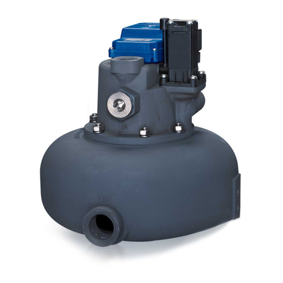
Original installation and operation manual BEKOMAT 16 CO ® 3. Product information 3.1 Product description The BEKOMAT is an electronically level-controlled condensate drain used for draining off condensate in compressed ® gas systems. The condensate formed is collected in the BEKOMAT and the filling level is monitored by an integrated capacitive ®... -
Page 12: Function Description
BEKOMAT ® 16 CO Original installation and operation manual 3.3 Function description Illustration Description / explanation The condensate flows via the condensate inlet [C] into the BEKOMAT and collects in the housing [21]. The filling ® level in the housing [21] is permanently monitored by a capacitive sensor in the sensor tube [46]. -
Page 13: Type Plate
2000787 +1° ... + 60 °C / 34° ... 140 °F 14266245 230 Vac ± 10% /50 ... 60Hz/ <8VA IP65 Made in Germany BEKO TECHNOLOGIES GmbH 14136065 BEKO TECHNOLOGIES GmbH Example illustrations 14136065 Position on type plate Description / explanation... -
Page 14: Technical Data
BEKOMAT ® 16 CO Original installation and operation manual 4. Technical data 4.1 Operating parameters BEKOMAT 16 CO ® 0.8 ... 16 bar(g) Min. / max. operating pressure 12 ... 230 psi(g) +1 … +60 °C Min./max. operating temperature +34 … +140 °F +1 …... -
Page 15: Storage And Transport Parameters
Original installation and operation manual BEKOMAT 16 CO ® 4.2 Storage and transport parameters BEKOMAT 16 CO ® Min. / max. storage and transport +1 … +60 °C temperature +34 … +140 °F 4.3 Materials BEKOMAT 16 CO ® Housing Aluminium, hardcoated Membrane 15 | 60... -
Page 16: Climatic Zones And Performance Data
BEKOMAT ® 16 CO Original installation and operation manual 4.4 Climatic zones and performance data Depending on which climatic zone the product is used in, the product performance differs depending on the climatic ambient conditions. Climatic zone Max. compressor performance Max. -
Page 17: Dimensions
Original installation and operation manual BEKOMAT 16 CO ® 4.5 Dimensions mm (inch) i = innen/inside a = außen/outside 17 | 60... -
Page 18: Installation Dimensions
BEKOMAT ® 16 CO Original installation and operation manual 4.6 Installation dimensions Illustration Description / explanation G3/4 (3/4“ NPT) At the place of installation, allow sufficient assembly space above the top cover so that the G1/2 LEDs are visible and the TEST button can be pressed. -
Page 19: Transport And Storage
5.1 Transport After transporting and removing the packaging material, inspect the product for possible transport damage. If you detect any damage, immediately notify the carrier company and BEKO TECHNOLOGIES GMBH or one of its agents. Transport the product as follows: •... -
Page 20: Assembly
BEKOMAT ® 16 CO Original installation and operation manual 6. Assembly 6.1 Warning notices DANGER Use of incorrect spare parts, accessories or materials! The use of incorrect spare parts, accessories or materials, as well as auxiliary and operating materials, may result in death or serious injury. Malfunction and device failure as well as material damage can occur. -
Page 21: General Assembly Instructions
Original installation and operation manual BEKOMAT 16 CO ® 6.1.1 General assembly instructions Note the following assembly instructions at all times. Wrong Right Description / explanation Bypassing the filter! Drain each point where condensate occurs separately in order to avoid bypassing the filters! Avoid pressure ranges! Drain each point where condensate occurs using a BEKOMAT... - Page 22 BEKOMAT ® 16 CO Original installation and operation manual Wrong Right Description / explanation Deflecting surface! In the case of direct drainage from the compressed gas line a deflection of the compressed gas flow is necessary! Continuous slope! If a pressure hose is used for inflow, avoid the formation of a water pocket! Continuous slope! When laying pipes for the feed line, avoid the...
-
Page 23: Installation
Original installation and operation manual BEKOMAT 16 CO ® 6.2 Installation For assembly work to be carried out, the following prerequisites must be fulfilled and the preparatory tasks must have been completed. Prerequisites Tools Material Protective equipment • e.g. adjustable spanner •... -
Page 24: Electrical Installation
BEKOMAT ® 16 CO Original installation and operation manual 7. Electrical installation 7.1 Warning notices DANGER Use of incorrect spare parts, accessories or materials! The use of incorrect spare parts, accessories or materials, as well as auxiliary and operating materials, may result in death or serious injury. Malfunction and device failure as well as material damage can occur. -
Page 25: Connection Work
Original installation and operation manual BEKOMAT 16 CO ® 7.2 Connection work For connection work to be carried out, the following prerequisites must be fulfilled and the preparatory tasks must have been completed. Prerequisites Tools Material Protective equipment • Stripping tool •... - Page 26 BEKOMAT ® 16 CO Original installation and operation manual Illustration Description / explanation 5. Raise the top cover [3] a little and pull the cable terminal [10] of the power control board up and off. 6. Unscrew the pan-head screw [12] and take the power control board [11] out of the top cover [3].
- Page 27 Original installation and operation manual BEKOMAT 16 CO ® Illustration Description / explanation 10. Insert the power control board [11] back into the top cover [3] and fasten using the pan-head screw [12]. Tighten the voltage supply cable [I] while doing this and screw the components of the cable gland [4, 5, 6] in place.
-
Page 28: Power Control Board Dc
BEKOMAT ® 16 CO Original installation and operation manual 7.2.1.2 Power control board DC Illustration Description / explanation 1. Loosen the 4 pan-head screws [2] in the top cover and unscrew the components of the cable gland [4, 5, 6, 2. - Page 29 Original installation and operation manual BEKOMAT 16 CO ® Illustration Description / explanation Normally Open (NO) Common (CO) Normally Closed (NC) ±24V +24 VDC (0 V) ±24V 0 V (+24 VDC) 6. Connect the voltage supply cable to the power control board in accordance with the terminal diagram.
-
Page 30: Connection Of Potential Free Contact
BEKOMAT ® 16 CO Original installation and operation manual 7.2.2 Connection of potential free contact The BEKOMAT has a potential-free contact on the power control board. A fault signal can be indicated at a remote ® maintenance centre through this. Illustration Description / explanation 1. -
Page 31: Connection Of External Test
Original installation and operation manual BEKOMAT 16 CO ® 7.2.3 Connection of external TEST The BEKOMAT has an option for the connection of an external TEST button. This enables condensate to be discharged ® via remote control. If the external contact is closed, the solenoid valve opens like after pressing the TEST button on the top cover and the BEKOMAT discharges condensate. -
Page 32: Commissioning
BEKOMAT ® 16 CO Original installation and operation manual 8. Commissioning 8.1 Warning notices DANGER Pressure build-up in the pipework! Death or serious personal injury can result through contact with fast or suddenly escaping compressed gas or through bursting system parts. •... -
Page 33: Commissioning Tasks
Original installation and operation manual BEKOMAT 16 CO ® 8.2 Commissioning tasks Illustration Description / explanation 1. Supply the BEKOMAT ® with voltage. 2. Slowly charge the system section with pressure. To do this, slowly open the shut-off valve [E]. 9. -
Page 34: Operating States
BEKOMAT ® 16 CO Original installation and operation manual 9.1 Operating states Illustration Description / explanation Disconnected • All LEDs are off Switch on / power-on self-test • All LEDs light up for 1 second n = 2 Positive power-on self-test (repeat 2x) •... -
Page 35: Maintenance
Original installation and operation manual BEKOMAT 16 CO ® 10. Maintenance 10.1 Warning notices DANGER Pressure build-up in the pipework! Death or serious personal injury can result through contact with fast or suddenly escaping compressed gas or through bursting system parts. •... -
Page 36: Maintenance Work
BEKOMAT ® 16 CO Original installation and operation manual 10.3 Maintenance work For maintenance work to be carried out, the following prerequisites must be fulfilled and the preparatory tasks must have been completed. Prerequisites Tools Material Protective equipment • Screwdrivers: •... - Page 37 Original installation and operation manual BEKOMAT 16 CO ® Illustration Description / explanation 4. Loosen the fixing screws of the solenoid valve connector [49]. 5. Pull the solenoid valve connector [51] off. 6. Loosen the cylinder head screws [29]. 37 | 60...
- Page 38 BEKOMAT ® 16 CO Original installation and operation manual Illustration Description / explanation 7. Remove the magnet coil [32] together with the control-air cover [34] and the membrane cap [28]. 8. Loosen the pan-head screws [35] and dismantle the solenoid valve in accordance with the drawing. 38 | 60...
- Page 39 Original installation and operation manual BEKOMAT 16 CO ® Illustration Description / explanation 9. Loosen the hexagon nuts [37] with the spring washers [36] and take the housing upper part [41] off. The intervals for wear part replacement and the necessary cleaning work are identical. Recommended interval: Carry out cleaning work in the disassembled state at the same time as wear part replacement.
- Page 40 BEKOMAT ® 16 CO Original installation and operation manual Illustration Description / explanation 11. Set the housing upper part in place again [41] and screw tight using the hexagon nuts [37] and spring washers [36] . 12. Assemble the solenoid valve again in accordance with the drawing and screw together using the pan-head screws [35] .
- Page 41 Original installation and operation manual BEKOMAT 16 CO ® Illustration Description / explanation 13. Set the solenoid valve [32] in place together with the control-air cover [34] and the membrane cap [28] and screw tight using the cylinder head screws [29]. 14.
- Page 42 BEKOMAT ® 16 CO Original installation and operation manual Illustration Description / explanation 15. Fit the cable terminals [10, 13, 14] and the top cover [3]. 16. Screw the 4 pan-head screws [2] tight. 42 | 60...
-
Page 43: Cleaning Work
Original installation and operation manual BEKOMAT 16 CO ® 10.3.2 Cleaning work Clean the BEKOMAT using a damp (not dripping wet) cotton cloth or disposable wipe, a cleaning brush and a mild, ® conventional cleaning agent/soap. Spray the cleaning agent on a clean cotton cloth or disposable wipe and wipe down the entire component. Then dry using a clean cloth or let it dry at room temperature. -
Page 44: Visual Inspection
The leakage test is a non-destructive test method and is used to prove leak tightness in vacuum and overpressure systems. The leakage test can be carried out in different ways. BEKO TECHNOLOGIES GmbH does not make a specific recommendation here. The company operating the compressed gas system is responsible for the selection and specification of the test method to be used, which should be executed in accordance with valid standards and regulations (e.g. -
Page 45: Consumables, Accessories And Spare Parts
Material number and designation of the accessory or spare part • Required quantity of accessories or spare parts to be delivered The contact data for the BEKO TECHNOLOGIES customer services responsible are listed in chapter “1.1 Contact” on Page 4. 11.2 Accessories Illustration Description / explanation &... -
Page 46: Spare Parts
BEKOMAT ® 16 CO Original installation and operation manual 11.3 Spare parts Illustration Description / explanation & order reference Set of wear parts 2000087 Membranes, 3 pcs. 4002451 Valve unit, complete 2000089 46 | 60... - Page 47 Original installation and operation manual BEKOMAT 16 CO ® Illustration Description / explanation & order reference Valve attachment components 2000088 Set of seals 2000090 Housing 2000092 47 | 60...
- Page 48 BEKOMAT ® 16 CO Original installation and operation manual Illustration Description / explanation & order reference Top cover 2000066 Control PCB 4047984 Power control board 230 VAC 2000063 Power control board 200 VAC 2000349 Power control board 115 VAC 2000064 Power control board 100 VAC 2000611 Power control board 24 VAC...
-
Page 49: Decommissioning
Original installation and operation manual BEKOMAT 16 CO ® 12. Decommissioning 12.1 Warning notices DANGER Pressure build-up in the pipework! Death or serious personal injury can result through contact with fast or suddenly escaping compressed gas or through bursting system parts. •... -
Page 50: Disassembly
BEKOMAT ® 16 CO Original installation and operation manual 13. Disassembly For dismantling work to be carried out, the following prerequisites must be fulfilled and the preparatory tasks must have been completed. Prerequisites Tools Material Protective equipment • e.g. adjustable spanner Always to be worn: Preparatory tasks Depressurise the compressed gas system or the respective system section and secure it against unintentional... -
Page 51: Disposal
Original installation and operation manual BEKOMAT 16 CO ® 14. Disposal 14.1 Warning notices NOTE Inappropriate disposal! Inappropriate disposal of parts and components, operating and auxiliary materials as well as cleaning media can cause environmental damage. • Dispose of all components and parts, operating and auxiliary materials as well as cleaning media professionally and in accordance with regional legal provisions, regulations and requirements. -
Page 52: Disposal Work
BEKOMAT ® 16 CO Original installation and operation manual 14.2 Disposal work At the end of its useful life, dispose of the product properly e.g. through a specialist company. Do not dispose of electrical and electronic components via municipal waste disposal companies or household waste. Materials such as e.g. glass, plastic are recyclable to a major extent and can be used again. -
Page 53: Troubleshooting / Faq
Original installation and operation manual BEKOMAT 16 CO ® 15. Troubleshooting / FAQ Illustration Description / explanation Troubleshooting • Read the operating voltage off on the type plate and check it • Check whether voltage is applied to the terminals All LEDs off of the power control board (PE, L, N) •... -
Page 54: Appendices
BEKOMAT ® 16 CO Original installation and operation manual 16. Appendices 16.1 Approval certificates and declarations of conformity Symbol Description / explanation CE marking The CE marking indicates that a product fulfils all the EU directives applicable for this product and that basic safety and health requirements were met during manufacturing of the product. The product may be sold on the European market. - Page 55 Original installation and operation manual BEKOMAT 16 CO ® 55 | 60...
-
Page 56: Exploded Drawing
BEKOMAT ® 16 CO Original installation and operation manual 16.2 Exploded drawing 56 | 60... - Page 57 Original installation and operation manual BEKOMAT 16 CO ® Pos. no. Description / explanation Pos. no. Description / explanation Operating label with TEST button [29] Cylinder head screw M5 x 20 Pan-head screw M3 x 10 [30] Valve core with conical spring Top cover [31] O-ring 25 x 1.5 mm...
- Page 58 BEKOMAT ® 16 CO Original installation and operation manual 58 | 60...
- Page 59 Original installation and operation manual BEKOMAT 16 CO ® 59 | 60...
- Page 60 Tel. +86 21 508 158 85 info.cn@beko-technologies.cn BEKO Tecnológica España S.L. BEKO TECHNOLOGIES LIMITED BEKO TECHNOLOGIES INDIA Pvt. Ltd. Torruella i Urpina 37-42, nave 6 Unit 1010 Miramar Tower Plot No.43/1 CIEEP Gandhi Nagar E - 08758 Cervelló 132 Nathan Rd.