Advertisement
Quick Links
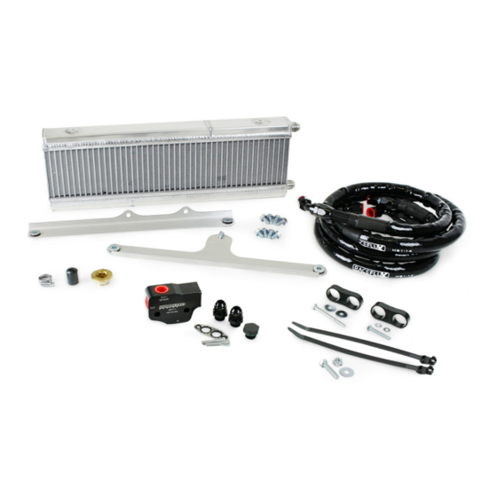
OIL COOLER KIT FOR 2012-2015
CHEVROLET CAMARO V8
PART NUMBER: E5G-601
MADE IN USA
Important: Read these instructions in their
entirety prior to installation
For contact information, visit www.improvedracing.com
Copyright © 2008-2019 Improved Racing Products, LLC. All rights reserved.
Rev 190528
Advertisement

Related Manuals for Improved Racing E5G-601


Summary of Contents for Improved Racing E5G-601
- Page 1 OIL COOLER KIT FOR 2012-2015 CHEVROLET CAMARO V8 PART NUMBER: E5G-601 MADE IN USA Important: Read these instructions in their entirety prior to installation For contact information, visit www.improvedracing.com Copyright © 2008-2019 Improved Racing Products, LLC. All rights reserved. Rev 190528...
- Page 2 APPLICATIONS • Improved Racing’s E5G-601 oil cooler kit is designed for direct installa- tion on the following vehicles: ◦ 2012-2015 Chevrolet Camaro V8 (SS & ZL1) ◦ Z/28 Camaros may require additional parts for deleting the factory installed heat exchangers and fans.
-
Page 3: Technical Specifications
E5G-600-62 Hardware Pack Contents Item Part Number Description CP-16 Billet Aluminum Hose Separator HSC-1052 Grade 5 Hex Head Screw, , L = 2- inch HWA-1004 inch Washer E5G-600-63 Hardware Pack Contents Item Part Number Description CP-16-01 Billet Aluminum Hose Separator HSC-1053 8.8 Class Alloy Steel M6x1.00x40 Screw HWA-1003... - Page 4 SAE #4 (DIN 3017) 430 Stainless Steel Smooth Band, Worm- HCP-1022 Info Drive Hose Clamp, Wrench Flat = inch (7 mm), MAX Torque = 20 lb-in (2.3 N-m) Genuine GM LS Family Engine Coolant Plug, 17 mm Hexagon 12561663 Info Drive, Yellow Brass, Thread-Lock Applied -10 Hose Assembly: 90°...
- Page 5 Figure 1 - Removing the Pop-Clips and Screws 6. Underneath the car, use a 10 mm tool to remove the two screws which hold the bumper cover to the chassis, circled in green on Figure 2. Figure 2 - Removing the Bottom Bumper Cover Screws 7.
- Page 6 Figure 4 - Removing the Wheel Well Cover to Bumper Cover Screws 9. Peel-back the wheel-well linings on each side to: Use a 7 mm tool to remove one screw securing the bumper cover to the fender. b. Use an extended 10 mm socket wrench to remove four screws secur- ing the bumper cover to the fender support.
- Page 7 REMOVING THE FACTORY OIL COOLER 1. Place a drain pan under the oil filter and remove the filter. 2. Remove the lower radiator shroud from the car by removing four push- green clips, circled in on Figure 6. Tip: Removing the bumper bar makes this easier Figure 6 - Removing the Lower Radiator Shroud 3.
- Page 8 4. Locate the clamp that holds the oil cooler tube to the oil pan and remove the flange nut with a 10 mm tool, circled in green on Figure 8. OIL PAN Figure 8 - Removing the Flange Nut from the Hose Clamp 5. Remove the clover-shaped wire clip from the large engine coolant fitting using a pic or two flat screwdrivers, circled in green on Figure 9. Figure 9 - Removing the Clover-Like Metal Clip 6.
- Page 9 b. Loosely place the #20 line back into the #2/3 engine fitting. Locate the #22 radiator hose circuit that feeds the factory oil cooler. d. Place HPL-1001 and HCP-1022 from the E5G-681 Hardware Kit within arms reach. Place a 7 mm ( inch) tool within arms reach. Use channel-lock pliers to remove the #21 hose clamp from the #22 radiator hose and slide it back past the barb.
- Page 10 9. Use a 17 mm hex bit to install the new brass coolant plug, GM part 12561663, into the engine block. 10. Torque the coolant plug to 45 lb-ft (60 N-m), followed by a turn. 11. Use a 13 mm tool to remove the four M8 screws that hold the factory oil cooler to the side of the oil pan.
- Page 11 INSTALLING THE IMPROVED RACING KIT 1. Familiarize oneself with EGM-114 and MHX-245 by reading the in- cluded manuals. 2. Install the adapter fittings into EGM-114. Torque the fittings to 20 lb-ft (27 N-m). 3. Install EGM-114 using a 5 mm hex-drive tool. Tip: Cut a 5 mm key on the short side to make a low profile tool should your headers interfere 4. Use E5G-600-60 and E5G-600-61 Hardware Kits to secure the top and bottom brackets to MHX-245, as shown in Figure 12.
- Page 12 6. Use an angle finder to match the 4° tilt of the factory radiator stack and hold this position to trace the hole for the lower bracket. Tip: When on wheel ramps, re-measure the angle on your ramps. 7. Use a permanent marker to trace the hole outline for drilling. 8. Remove the cooler and bracket assembly from the car. 9.
- Page 13 13. Apply oil to the adapter fitting’s flare on the OUT port of EGM-114, and connect the straight hose-end of E5G-600-51. Torque the hose-end to 20 lb-ft (27 N-m). 14. Repeat Step 13 of this section with E5G-600-50 for the IN port on EGM- 114. Torque the fitting to 20 lb-ft (27 N-m). Tip: Connect the 90° hose-end with heat shield at the adapter side. 15.
- Page 14 16. Locate the threaded hole on the top of the chassis for the next clamp, shown in Figure 17, and secure the hoses with E5G-600-63 Hardware Kit as shown in Figure 18. Tip: Use channel-lock pliers to keep the hose clamp straight while tight- ening.
- Page 15 17. Peel-back the black plastic shroud circled in green on Figure 19 and route the system lines up towards MHX-245. Figure 19 - Black Plastic Shroud to Peel-Back & Route Hoses 18. Use two HTD-1004 from the E5G-600-64 Hardware Kit to secure the hoses onto the M8 screw that was installed into the washer fluid tank previously, as shown in Figure 20.
- Page 16 20. Pre-fill the heat exchanger with engine oil using a tube and funnel. Tip: Use a flexible tube with a MAX O.D. of 0.50” (12.7 mm). 21. Remove the tube and funnel followed by connecting the 90° hose-end to the top fitting on the oil cooler. Tighten the hose-end to 20 lb-ft (27 N-m). Wipe-up any oil that spills. PREPARING FOR STARTING 1. Check the engine oil level and add oil if necessary. 2. Remove the fuel injector fuses. Tip: Consult the vehicle’s factory service manual for the fuse locations.
- Page 17 13. Close the hood and safely lower vehicle back onto the ground. 14. Take a test drive to ensure performance is as desired. 15. Check for loosened fittings and leaks after 50 miles of driving. Installation is now complete. Thank you for purchasing an Improved Racing product! Visit www.improvedracing.com for additional support...
Need help?
Do you have a question about the E5G-601 and is the answer not in the manual?
Questions and answers