
Related Manuals for Riello Burners GAS 6


Summary of Contents for Riello Burners GAS 6
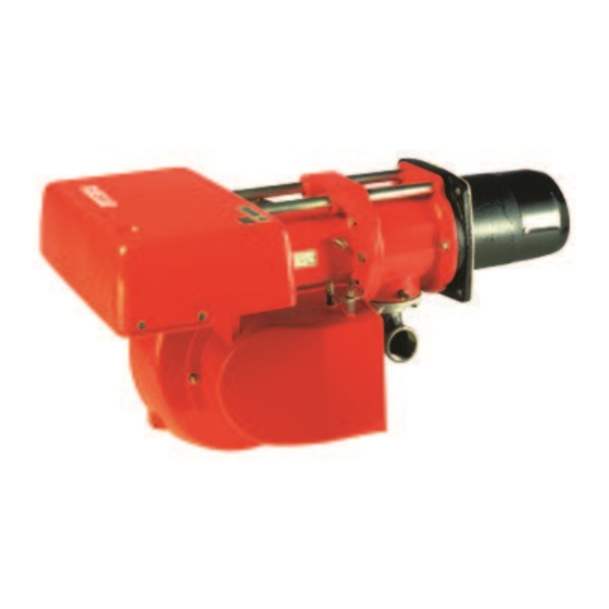
- Page 1 Installation, use and maintenance instructions Gas burner CODE MODEL TYPE 3751882 GAS 6 518 T80 2915862 (1)
-
Page 2: Technical Features
TECHNICAL FEATURES Thermal output 520 - 1050 kW 447.200 - 903.000 kcal/h Fuel Natural gas Pci 8 - 10 kWh/m = 7000 - 8600 kcal/m For maximum output 12.3 mbar are needed measured at the coupling Minimum gas pressure with nil pressure in the combustion chamber and gas with calorific value of 8600 kcal/m Maximum gas pressure 150 mbar... -
Page 3: Gas Supply
EQUIPMENT Quantity Burner accessories Flange Gasket Screws Flange gasket FIXING TO THE BOILER Separate the combustion head from the burner body by loosening the screws 1) and 2) and withdrawing the group A) from the holding bars 3). Fix the group B) to the boiler front plate 4) using the gasket 5) provided as acces- sory. -
Page 4: Working Range
WORKING RANGE COMBUSTION CHAMBER PRESSURE MAXIMUM OUTPUT (in compliance with DIN 4788) kcal/h D1795 MINIMUM GAS PRESSURE - OUTPUT Pressure : detected at the pressure test-point 8) (fig. 1) with nil mbar into the combustion chamber. Should the combustion chamber be pressurized, the pressure necessary will be that of the graph plus the pressurization value. - Page 5 BURNER ELECTRICAL WIRING (carried out in the factory) D2656 KEY TO LAYOUT CMV Fan motor contactor TTENTION Protection against radio interference Relay In the case of phase-phase feed, a Burner terminal strip bridge must be fitted on the control box Fan motor Air pressure switch terminal board between terminal 6 and...
- Page 6 ELECTRICAL CONNECTIONS TO THE WIRING TERMINAL BLOCK (to be carried out by the installer) KEY TO LAYOUT Remote lock-out signal Remote lock-out signal of leak detection control device Burner manual stop switch Burner terminal strip Min. gas pressure switch Safety control device system Limit control device system Leak detection control device Adjustement valve...
-
Page 7: Burner Start-Up Cycle
BURNER START-UP CYCLE Air-purge : loosen the screw placed on the minimal gas pressure switch mounted on the gas train Screw Plug for pressure measure Pressure switch S7506 AIR PRESSURE SWITCH 7) (fig.1) S7507 The air pressure switch setting shall be carried out after having set all other adjustment of the burner and the air pressure switch shall be at its lowest set-point. -
Page 8: Combustion Head Adjustment
COMBUSTION HEAD ADJUSTMENT Two separate adjustments have to be made: air and gas. These adjustments can be carried out when the burner is still open, during the installation (see page 2 - Fixing to the boiler). Air setting Loosen the two screws 1) and move the internal part of the combustion head 2) so that its rear edge 3) is coincident with the desired set-point on the plate 4). -
Page 9: Combustion Checks
COMBUSTION CHECKS It is advisable to not exceed 10% of CO (gas with calorific value of 8600 kcal/m ), in order to avoid the risk that small changes of the adjustments due, for instance, at draught variation, may cause com- bustion with insufficient air and consequently formation of CO. -
Page 10: Operating Faults
BURNER STARTING DIFFICULTIES AND THEIR CAUSES DIFFICULTIES CAUSES The burner goes through The ionization probe is earthed or not in contact with the flame, or the purge period normally, its wiring to the control box is broken, or there is a fault on its insu- the flame ignites, but the lation to earth. -
Page 11: Burner Start-Up Cycle Diagnostics
BURNER START-UP CYCLE DIAGNOSTICS During start-up, indication is according to the followin table: COLOUR CODE TABLE Sequences Colour code G G G G G G G G G G G Pre-purging G H G H G H G H G H G Ignition phase K K K K K K K K K K K K Operation, flame ok... - Page 12 RIELLO S.p.A. Via degli Alpini 1 I - 37045 Legnago (VR) Tel.: +39.0442.630111 Fax: +39.0442.630375 http:// www.rielloburners.com Subject to modifications...
Need help?
Do you have a question about the GAS 6 and is the answer not in the manual?
Questions and answers