Table of Contents
Advertisement
Advertisement
Table of Contents

Related Manuals for Fostex FD-4


Summary of Contents for Fostex FD-4
- Page 1 Service Manual Model FD-4 DIGITAL MULTITRACKER...
-
Page 2: Safety Instructions
CAUTION RISK OF ELECTRIC SHOCK DO NOT OPEN CAUTION: TO REDUCE THE RISK OF ELECTRIC SHOCK, DO NOT REMOVE COVER (OR BACK). NO USER-SERVICEABLE PARTS INSIDE. REFER SERVICING TO QUALIFIED SERVICE PERSONNEL. The lightening flash with arrowhead symbol, within an equilateral triangle, is intended to alert the user to the presence of uninsulated “dangerous voltage”... -
Page 3: Table Of Contents
Service mode, error code list, explode view, PCB assembly, parts list and circuit diagrams are given in this manual to assist the service technician in maintaining the Model FD-4. The following accessories are supplied with FD-4 as the standard accessories. -
Page 4: Specifications
FD-4 1. SPECIFICATIONS RECORD & REPRODUCE Recording Medium Standard Sampling Frequency Quantization Emphasis Recording Time (mono track min.) Fs: 32 kHz Fs: 44.1 kHz Number of Tracks NORMAL / MASTERING MODE 1 MASTERING MODE 2 Number of simultaneous recording tracks... - Page 5 MONITOR -10 dBV 73 dB or more MONITOR +2 dBV 85 dB or more PHONES FD-4 S / N AWTD. 68 dB or more 80 dB or more 82 dB or more 94 dB or more 65 dB or more...
- Page 6 FD-4 ELECTRICAL (continued) Distortion INPUT INPUT -40 dBV AUX RTN -10 dBV -10 dBV Crosstalk Click Noise Power on / off Other switching MIDI Controlling • RECORDER SECTION Frequency Response Fs: 44.1 kHz Fs: 32 kHz Full Scale Output Level (Ref: -12dB)
-
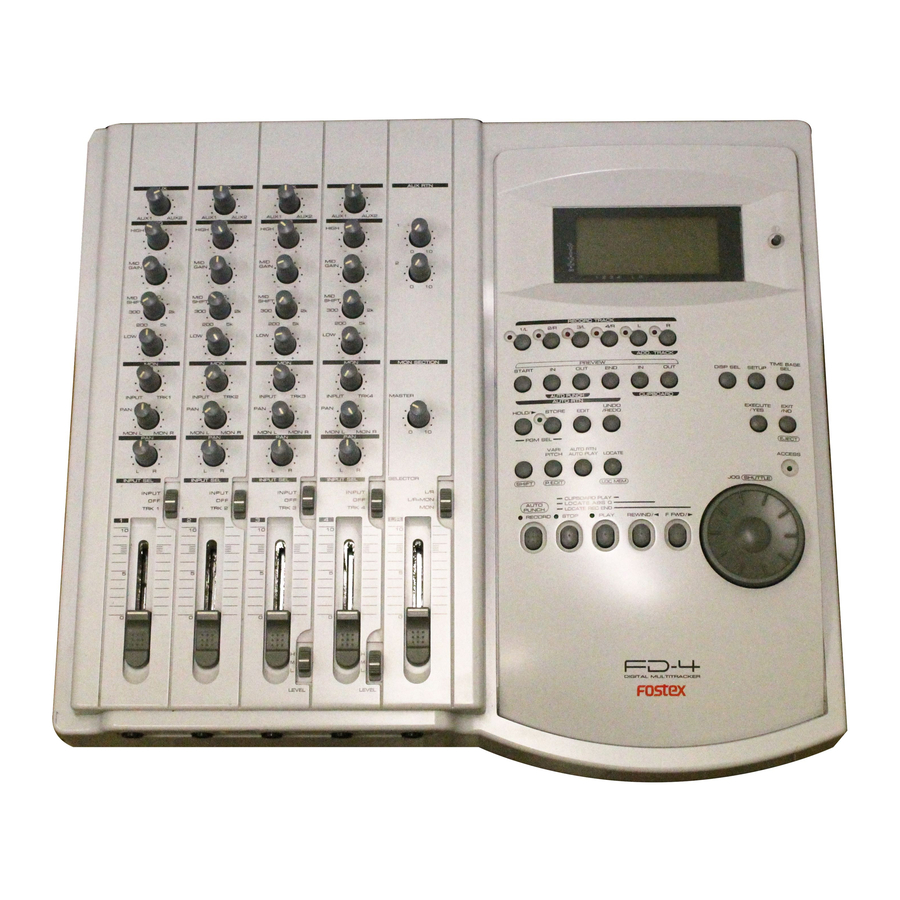
Page 7: Controls, Indicators And Connectors
CLIPBOARD AUTO RTN UNDO/ EXECUTE EXIT STORE EDIT REDO /YES EJECT VARI AUTO RTN PITCH AUTO PLAY LOCATE ACCESS SHUTTLE P. EDIT LOC MEM CLIPBOARD PLAY LOCATE ABS 0 LOCATE REC END STOP PLAY REWIND/ F FWD/ DIGITAL MULTITRACKER FD-4... - Page 8 FD-4 Control Panel (Mixer Section) HIGH GAIN SHIFT 1. Input faders [1-4] 2. Input select switches [INPUT SEL (INPUT/OFF/TRK)] 3. Panpot knobs [PAN (L/R)] 4. Monitor panpot knobs [PAN (MON L/MON R)] 5. Monitor level control knob [MON (INPUT/TRK)] 6. Equalizer control knobs [EQ (HIGH/MID/LOW)] 7.
- Page 9 39. Auto Punch Out key [AUTO PUNCH OUT/ 40. Clipboard In key [CLIPBOARD IN/ 41. Clipboard Out key [CLIPBOARD OUT/ TIME BASE DISP SEL SETUP EXECUTE EXIT /YES EJECT ACCESS SHUTTLE SHIFT P.EDIT LOC MEM PREVIEW PREVIEW PREVIEW PREVIEW PREVIEW PREVIEW FD-4...
- Page 10 FD-4 Front Panel 1. Input jacks [1, 2, 3, 4] (Phone) 2. Headphone jack [PHONES] (TRS Phone) Rear Panel POWER 1. Monitor Out jacks [MON OUT L, R] (RCA pin) 2. Stereo Out jacks [ST. OUT L, R] (RCA pin) 3.
-
Page 11: Software Update
If something wrong happens while updating the software (e.g. A blackout occurred while updating the software.), the FD-4 might not be able to boot up the system software inside the Flash ROM. In this case, please refer to the section “4- 8. -
Page 12: Service Mode
FD-4 4. SERVICE MODE There are various optional modes available in the FD-4 Service Mode. Please utilize them when servicing the unit. 4-1. Putting FD-4 into Service Mode The way of putting the FD-4 into Service Mode is as follow. - Page 13 SCSI AUTO A.PUNCH RHSL TAKE If the FD-4 is in a normal condition, all the segments on the 32kHz 44.1kHz 48kHz LCD display will lit solid and the LEDs on the top panel SETUP MTC OFFSET will start blinking. COMPLETED...
- Page 14 FD-4 Key/Button/Jog Dial RECORD STOP PLAY REWIND/ F FWD/ SHIFT VARI PITCH/ P.EDIT AUTO RTN/PLAY LOCATE/ LOC MEM HOLD/ STORE 4-5. Self Check In this condition, if the EXECUTE/YES key is pressed one more time, the Button Test can be executed.
- Page 15 SCSI A.PUNCH EXECUTE/YES key. If the FD-4 is in a good shape, “Check OK!” will be displayed and the FD-4 is automatically put into Input Monitor mode with all the RECORD TRACK LEDs and RECORD LED flashing after checking the points mentioned in the previous page.
-
Page 16: Midi Function
FD-4 The followings are examples of error message when the FD-4 is not working properly. • SCSI function • Digital Signal in/out (Fs: 44.1kHz) • Vari-pitch function 4-6. Offset Display • MIDI function SYNC OUT DRIVE SCSI AUTO A.PUNCH • Digital Signal in/out (Fs: 32kHz) 44.1kHz... - Page 17 “Zero File”. As shown in the diagram below, Audio Files and Zero Files will be alternately recorded on the FD-4 and each Audio File and Zero File are counted as individual “Event”. Thus, the number of events on a certain track is calculated by summing up these Audio Files and Zero Files.
- Page 18 FD-4 4-10. Free Block Check This Service Mode allows to check the Event Number : Blinking recorded on each track in one program on the FD-4. SETUP In order to check, press the EXECUTE/YES key while “?” is blinking. SYNC OUT...
-
Page 19: Error Code List
The chart below indicates the error code number and corresponding description. Since the error code list is basically designed for our engineers to improve the software, the description is quite technical. If you find the FD-4 with one of the error codes displayed, we encourage you to update the software first. -
Page 20: Installing 2.5" Internal Hard Disk Drive
• 14 x screws (P 3 x 4 CZn) Installing Procedures Loosen 14 x screws (BBT 3 x 8 BZn) which fix the FD-4 Top Panel section to the Bottom Panel section. Remove the following cables from the connectors on the MAIN PCB assy. - Page 21 Mount and solder the 50-pin connector and 2-pin cable. (Before soldering, you might need to remove the soldering by a solder remover.) Connector, PI, header, 50P, AMPMOD B 3 x 6 CZn Cable, flat, 2P, L150 BBT 3 x 8 BZn Fix-Stand FD-4...
- Page 22 B 3 x 6 B 3 x 4 CZn B 3 x 4 CZn B 3 x 4 CZn BBT 3 x 8 B 3 x 4 CZn Bracket, HD, FD-4 Fix-Stand...
- Page 23 • 9-pin cable to the J7 (coming from DISPLAY PCB assy) • 7-pin cable to the J10 (coming from MIXER A PCB assy) Tighten 14 x screws (BBT 3 x 8 BZn) which fix the FD-4 Top Panel section to the Bottom Panel section. BBT 3 x 8 BZn Cable assy, flat, 50P, P1.0, AMPMOD,...
-
Page 24: Exploded View, Pcb Assembly And Parts List
8274 1240 00 PCB assy, XLR, FD-4 8216 6641 00 Shield, mixer, FD-4 8226 2370 00 Button assy, control, FD-4 8274 1220 00 PCB assy, Mixer A, FD-4 8226 2230 01 Knob, volume, C 8274 1360 00 PCB assy, Display, FD-4... -
Page 25: Fd-4 Fd-
FD-4 FD-4 OVERALL EXPLODED VIEW... - Page 26 FD-4 PCB PATTERN DRAWING • Parts Side of MAIN PCB assy...
- Page 27 • Foil Side of MAIN PCB assy...
- Page 28 FD-4 • MIXER A, JACK and XLR PCB assys...
- Page 29 FD-4 • DISPLAY PCB assy...
- Page 30 • POWER and AC IN PCB assys...
- Page 31 FD-4 Parts List • MAIN PCB assy Ref. No. Part No. Description 8274 1370 00 PCB Assy, Main, FD-4 B001 8251 5191 00 Plain PCB, Main, FD-4 Ref. No. Part No. Description U001, 002 8236 5403 01 ST, analog, regulator,...
- Page 32 FD-4 RESISTORs Ref. No. Part No. Description R072 R073 8230 5000 00 ST, carbon, 1/10W, 0 , 5% R074~076 8230 5002 21 ST, carbon, 1/10W, 220 , 5% R077 8230 5001 03 ST, carbon, 1/10W, 10k , 5% R078 8230 5001 01 ST, carbon, 1/10W, 100 , 5%...
- Page 33 8232 1431 06 VT, ALU, 16V, 10µF, 20%, SME-VB C511~811 C112~412 8233 5006 81 ST, CER, 50V, 680pF, 5%, CC20SL C512~812 C113, 213 8233 5041 03 ST, CER, 25V, 0.01µF, 10%, CC20R C313, 413 C114, 214 8233 5041 03 ST, CER, 25V, 0.01µF, 10%, CC20R FD-4...
- Page 34 FD-4 Ref. No. Part No. Description C314, 414 C115~815 C116~416 8232 1434 76 VT, ALU, 16V, 47µF, 20%, SME-VB C516~816 C161~461 C162, 262 8233 5041 03 ST, CER, 25V, 0.01µF, 10%, CC20R C362, 462 C163, 263 8232 1434 76 VT, ALU, 16V, 47µF, 20%,...
- Page 35 W102, 202 8230 5000 00 Resistor, ST, carbon, 1/10W, 0 , 5% • MIXER A PCB assy Ref. No. Part No. Description 8274 1220 00 PCB Assy, Mixer A, FD-4 B001 8251 9672 01 Plain PCB, Mixer A, FD-4 Ref. No. Part No. Description...
- Page 36 FD-4 Ref. No. Part No. Description R537~837 8230 1382 20 HT, carbon, 1/4W, 22 , 5% R540~840 8240 2500 00 Pot., PI, SL45, 50k A, NS-4502VP, L20 R541~841 8240 2680 00 Pot., PI, RT09, 10k B, CC, EVUF3A, L20 R542~842 8240 2700 00 Pot., PI, RT12, 50k CC,...
- Page 37 8277 4530 40 Cable assy, shiled 2C, 6P, WHT8283-9073, L400 • JACK PCB assy Ref. No. Part No. Description 8274 1230 00 PCB Assy, JACK, FD-4 B001 8251 9672 02 Plain PCB, JACK, FD-4 Ref. No. Part No. Description Q001~006...
- Page 38 FD-4 • DISPLAY PCB assy Ref. No. Part No. Description 8274 1360 00 PCB Assy, Display, FD-4 B001 8251 5181 00 Plain PCB, Display, FD-4 Ref. No. Part No. Description U001 8236 0835 01 QFP, digital, CPU, FD4-display U002 U003...
- Page 39 8207 0100 13 Spacer, LED, 13 Y1004 8207 0100 14 Spacer, LED, 14 Y1005 Y1006 8212 6110 00 Plate, reflect, LCD, FD-4 Y1007 8207 0100 09 Spacer, LED, 9 Y1008 8207 0100 12 Spacer, LED, 12 • POWER PCB assy Ref.
- Page 40 FD-4 • AC IN PCB assy Ref. No. Part No. Description 8274 1390 00 PCB Assy, AC In, FD-4 B101 8251 9691 02 Plain PCB, AC In, FD-4 Ref. No. Part No. Description C001 8232 3521 04 Capacitor, V, PES, 250VAC, 0.1µF, 20%, ECQ-UMV...
-
Page 41: Circuit Diagrams
FD-4 8. CIRCUIT DIAGRAMS... - Page 42 MIXER A (1/6) REPRO INPUT5 /REC MUTE5-8 REPRO5 REPRO5 REPRO5 REPRO6 REPRO7 REC MUTE5 REC MUTE5 REPRO8 R.MUTE5 R.MUTE6 R.MUTE7 +12V +12V R.MUTE8 AGND AGND AGND -12V -12V INPUT6 REPRO6 REPRO6 REC MUTE6 REC MUTE6 +12V +12V AGND AGND -12V -12V INPUT BAL INPUT7...
- Page 43 MIXER A (2/6) C152 R155 120K +12V C150 47/10 AUX1 C151 4558 -12V C252 R255 120K +12V C250 47/10 AUX2 C251 4558 -12V STEREO L STEREO R C170 R170 47/10 AUX RTN 1L R172 C172 470P C270 R270 R12A 47/10 30KAA AUX RTN 1R R272...
- Page 44 MIXER A (3/6) +12V C530 C503 100P C504 R504 C502 R502 47/10 10/16 U501A 4558 R503 100k J501 C531 -12V INPUT5 R501 U510 C501 100k DTC143 100P REC MUTE5 REPRO5 +12V R536 +12V AGND -12V AGND R537 -12V C512 R517 R520 R516 100P...
- Page 45 MIXER A (4/6) +12V C630 C603 100P C604 R604 C602 R602 47/10 10/16 U601A 4558 R603 100k J601 C631 -12V INPUT6 R601 U610 C601 100k DTC143 100P REC MUTE6 REPRO6 R636 +12V +12V AGND -12V AGND R637 -12V C612 R617 R616 100P MID GAIN...
- Page 46 MIXER A (5/6) GAIN *40dB *20dB *0dB R708 S701B C704 R706 100/10 R710 200K J701 R704 200K INPUT7 UNBAL C702 R702 100P 100k C707 C701 R701 100k 100P U401A 2068 S701A C703 INPUT7H R707 100/10 INPUT7C R705 R703 R709 200K 200K INSERT7 SEND INSERT7 RTN...
- Page 47 MIXER A (6/6) GAIN *40dB *20dB *0dB R808 S801B C804 R806 100/10 R810 200K J801 R804 200K C802 INPUT8 UNBAL R802 100P 100k C807 C801 R801 100k 100P U401B 2068 S801A C803 R807 INPUT8H 100/10 INPUT8C R805 R803 R809 200K 200K INSERT8 SEND INSERT8 RTN...
- Page 48 ANALOG I/O & XLR A U X RTN 1 L /MO N O A U X RTN 2 L /MO N O IN SE RT7 IN SE RT8 A U X RT N 1 L A U X RT N 1 R A U X RT N 2 L A U X RT N 2 R IN SE RT7 SE N D...
- Page 49 DISPLAY, ROOT (1/3) 10/16 10/35 0.1A Non_79L05A (F10 JUMPER) /ATN1 > RxD1 < TxD1 > SCK1 > To MAIN /ATN2 < /RST_DISP > DGND A-12 BOADIN 9P DGND DGND DGND DGND Non_10/16 E101 DGND Non_JUMPER Non_0.1 (-12V) Vlcd /ATN1 /ATN2 JOG1 470p JOG0...
- Page 50 DISPLAY, LCD (2/3) DGND DGND Vlcd Vlcd Non_1/50 (F5 Jumper) Non_LA5640N Lo< CONTRAST >Hi DGND DB[0..7] DB[0..7] SEG[1..40] SEG22 SEG39 SEG22 SEG39 SEG21 SEG40 SEG21 SEG40 SEG20 COM16 SEG20 COM16 SEG19 COM15 SEG19 COM15 SEG18 COM14 SEG18 COM14 SEG17 COM13 SEG17 COM13 SEG16...
- Page 51 DISPLAY, KEY & LED (3/3) JOG0 JOG1 SCAN[0..4] SCAN[0..4] SCAN0 Non_TACT SCAN1 Non_TACT SCAN2 UNDO/REDO SCAN3 SCAN4 Non_TACT R30 22k DGND KEY[0..7] KEY[0..7] R39 1k LED_A0 2SA1150 R40 1k LED_A1 Non_LED_R 2SA1150 Non_LED_R LED_K7 LED_K[0..7] LED_K[0..7] R19 10k R17 100k R18 10k 0.01 R22 10k...
- Page 52 FD-4...
- Page 53 MAIN, ROOT (1/9) AD-DA A+12 AGND HP AD-DA A+12 AGND A-12 MUTE REC_L REC_R A-12 AGND 8283M7P REC_L REC_R TO MIXER W101 A+12 RCA-JACK-SW J101 A-12 L101 W201 REC IN J201 AGND D+5_1 L201 RCA-JACK-SW DGND1 AGND DGND TO DISPLAY R_ADDA.SCH DGND -12V...
- Page 54 MAIN, CPU (2/9) R_MUTE1 R_MUTE2 R_MUTE3 R_MUTE4 ADDA R_MUTE[1..4] R_MUTE[1..4] A-12 A-12 SSSF1 DGND DGND MEMORY DGND /EPROM /EPROM FM_RDY FM_RDY D[0..15] D[0..15] D[0..15] A[0..18] A[0..18] A[0..18] MEMORY DGND DGND DGND RDWR RDWR RDWR /CS0 /CS0 /CS0 /CS2 /CS2 /CS2 /RAS /RAS /RAS...
- Page 55 MAIN, MEMORY (3/9) EPROM1 EPROM2 DGND 0.01 HN27C4001G DGND Under 2M 2M of 4M DGND FM_RDY /CS0 /CS_EPROM /CS0 /CS2 /CS2 /CS2 /CS_FLMEM /CS0 /EPROM 74HC157 0.01 DGND DGND DGND DGND FLASH MEMORY DQ10 DGND DQ11 DQ12 DQ13 DQ14 DQ15 0.01 HN27C4001G C100...
- Page 56 MAIN, AUDIO IF (4/9) V CO + 5 V CO + 5 PO W ER V CO G N D D + 5 V CO G N D 0.01 0.01 10/16 D + 5 PO W ER D + 5 0.01 D G N D D G N D...
- Page 57 MAIN, SCSI (5/9) /ATA_RST DMARQ IORDY_I INTRQ /ATA_RST DGND DD10 DD11 DD12 DD13 DD14 DD15 /DIOW DGND /DIOR KEYPIN /DMACK DMARQ DGND /DIOW DGND /DIOR DGND IORDY DMACK DGND INTRQ /IOCS16 ATA1 /PDIAG ATA0 ATA2 /CS1FX /CS3FX /DASP DGND DGND 2P JUMPER TO IDE HD DGND...
- Page 58 MAIN, ADDA - ROOT (6/9) G=-0.9dB C101 R101 R102 10/16 REC_L U101B R109 NJM2115M 100K C107 C104 MIXER 0.01 C201 R201 R202 10/16 REC_R U201B R209 100K C207 NJM2115M MUTE C204 0.01 R908 VBIAS R909 C903 C904 0.01 100/10 MUTE AGND A+12 RB400D...
- Page 59 MAIN, ADDA - DG (7/9) AIN2+ AIN2- AIN1+ AIN1- U151 C153 C154 AINR+ 10/16 0.01 AINR- SMODE VREF CMODE SDATA AGND FSYNC AINL+ LRCK AIN- SCLK C151 C152 TST1 MCLK HPFE 10/16 0.01 AGND TST2 SMODE2 TST3 TST4 D+5_1 DGND AK5351 R151 C156...
- Page 60 FD-4 MAIN, ADDA - OUT (8/9) C111 10/16 AOUT1+ R111 C211 10/16 AOUT2+ R211 C311 10/16 AOUT3+ R311 C411 10/16 AOUT4+ R411 A+12 C113 0.01 U153A C116 NJM4560M AGND 47/16 R113 2.7K R114 C115 100K C112 680P R112 AGND A-12 C114 0.01...
- Page 61 MAIN, VCO (9/9) PLL_SEL VCO+5 VCO+5 POWER VCOGND VCOGND FCONT1 VARI_FS VCO+5 22uH 0.01 VCO+5 VCOGND 1.2K LOCK 100K VDDA AMPI AMPO VSSA 0.047 1.2K 220P TC9246F 0.01 VCOGND VCOGND VCOGND 120P VCO+5 22uH 0.01 VCOGND 1.5K LOCK VDDA AMPI AMPO VSSA 220K...
- Page 62 FOSTEX CORPORATION 3-2-35 Musashino, Akishima, Tokyo, Japan 196-0021 FOSTEX CORPORATION OF AMERICA 15431 Blackburn Ave., Norwalk, CA 90650, U.S.A. © PRINTED IN JAPAN MAY 1998 8288771000...
Need help?
Do you have a question about the FD-4 and is the answer not in the manual?
Questions and answers