Table of Contents
Advertisement
Quick Links
Advertisement
Table of Contents

Related Manuals for Siemens SINUMERIK 840D sl OP 010


Summary of Contents for Siemens SINUMERIK 840D sl OP 010
- Page 1 General information and networking Description Operator control and display SINUMERIK elements Interfaces SINUMERIK 840D sl Operator panel front: OP 010 Installation Technical data Manual Spare parts Valid for: Control system SINUMERIK 840D sl/840DE sl 07/2018 A5E36371538B...
- Page 2 Note the following: WARNING Siemens products may only be used for the applications described in the catalog and in the relevant technical documentation. If products and components from other manufacturers are used, these must be recommended or approved by Siemens. Proper transport, storage, installation, assembly, commissioning, operation and maintenance are required to ensure that the products operate safely and without any problems.
-
Page 3: Table Of Contents
Table of contents General information and networking......................5 Fundamental safety instructions....................5 1.1.1 General safety instructions.......................5 1.1.2 Equipment damage due to electric fields or electrostatic discharge........8 1.1.3 Warranty and liability for application examples................8 1.1.4 Industrial security........................9 1.1.5 Residual risks of power drive systems...................10 Application planning.......................11 1.2.1 Secondary electrical conditions....................11... - Page 4 Table of contents 1.4.3.5 Application example.......................84 1.4.4 Service and diagnostics......................86 1.4.4.1 Booting of the TCU .......................86 Description..............................89 Operator control and display elements.......................91 View............................91 Keyboard..........................92 Screen saver..........................93 Interfaces..............................95 Installation..............................97 Preparation for mounting......................97 Assembling an OP 010 and a PCU..................98 Mounting on the mounting wall....................101 Softkey labeling........................102 Technical data............................103 Spare parts...............................105...
-
Page 5: General Information And Networking
General information and networking Fundamental safety instructions 1.1.1 General safety instructions WARNING Electric shock and danger to life due to other energy sources Touching live components can result in death or severe injury. ● Only work on electrical devices when you are qualified for this job. ●... - Page 6 General information and networking 1.1 Fundamental safety instructions WARNING Electric shock due to equipment damage Improper handling may cause damage to equipment. For damaged devices, hazardous voltages can be present at the enclosure or at exposed components; if touched, this can result in death or severe injury.
- Page 7 ● If you come closer than around 2 m to such components, switch off any radios or mobile phones. ● Use the "SIEMENS Industry Online Support app" only on equipment that has already been switched off. WARNING...
-
Page 8: Equipment Damage Due To Electric Fields Or Electrostatic Discharge
General information and networking 1.1 Fundamental safety instructions 1.1.2 Equipment damage due to electric fields or electrostatic discharge Electrostatic sensitive devices (ESD) are individual components, integrated circuits, modules or devices that may be damaged by either electric fields or electrostatic discharge. NOTICE Equipment damage due to electric fields or electrostatic discharge Electric fields or electrostatic discharge can cause malfunctions through damaged individual... -
Page 9: Industrial Security
Siemens’ products and solutions undergo continuous development to make them more secure. Siemens strongly recommends that product updates are applied as soon as they are available and that the latest product versions are used. Use of product versions that are no longer supported, and failure to apply the latest updates may increase customer’s exposure to cyber... -
Page 10: Residual Risks Of Power Drive Systems
General information and networking 1.1 Fundamental safety instructions WARNING Unsafe operating states resulting from software manipulation Software manipulations (e.g. viruses, trojans, malware or worms) can cause unsafe operating states in your system that may lead to death, serious injury, and property damage. ●... -
Page 11: Application Planning
General information and networking 1.2 Application planning 3. Hazardous shock voltages caused by, for example: – Component failure – Influence during electrostatic charging – Induction of voltages in moving motors – Operation and/or environmental conditions outside the specification – Condensation/conductive contamination –... -
Page 12: Grounding Concept
General information and networking 1.2 Application planning WARNING Inadequately fused supply cables can be life-threatening In the case of supply lines > 10 m, protectors must be installed at the device input in order to protect against lightning (surge). The DC power supply must be connected to the ground/shield of the NC for EMC and/or functional reasons. -
Page 13: Emc Compatibility
90°), but must never be laid close or parallel to one another. ● Only use cables approved by SIEMENS for the signal lines from and to the Control Unit. ● Signal cables must not be routed close to strong external magnetic fields (e.g. motors and transformers). -
Page 14: Ambient Climatic And Mechanical Conditions
General information and networking 1.2 Application planning ● If signal lines cannot be routed a sufficient distance away from other cables, they must be installed in grounded cable ducts (metal). ● The operator panel fronts, MCPs, MPPs, and full keyboards must be installed in metallically enclosed EMC-compatible housings. - Page 15 General information and networking 1.2 Application planning Table 1-2 Ambient conditions during storage and transport Type of condition Permissible range/class Transport Storage Classification EN 60721-3-2 EN 60721-3-1 Climate class Ambient temperature -40° C ... +70° C -25° C ... +55° C Biological environmental condi‐...
-
Page 16: Operating Conditions
● Do not open a battery. Replace a faulty battery only with the same type. ● Obtain replacement batteries only from Siemens. ● Always try to return low batteries to the manufacturer or deliver these to a registered recycling company. - Page 17 General information and networking 1.2 Application planning Environmental conditions Application areas Remarks Permissible ambient tempera‐ 0 ... 45 °C (32 ... 113 Except PCU50.5; ture when installed vertically °F), up to 2000 m front-side for OP, MCP/MPP and CNC (6562 ft) above sea standard keyboards KB.
-
Page 18: Cooling
General information and networking 1.2 Application planning 1.2.2.3 Cooling To calculate the heat dissipation, the total power loss P of all heat-generating components Vtotal in a housing must be taken into account. Total power loss P +... [W] Vtotal Convection surface area A [m The surface areas of the front and bottom sides are not included in the convection surface area calculation. - Page 19 General information and networking 1.2 Application planning Figure 1-1 Means of heat dissipation Fan design ● The fan must be positioned to produce an optimum heat dissipation. A clearance of 10 mm must be maintained in front of the fan. ●...
-
Page 20: Standards And Approvals
General information and networking 1.2 Application planning Guidelines If the convection area A [m ] does not suffice for the "heat dissipation using natural convection", then use: ● "Heat dissipation using natural convection and internal turbulence" for hot spots and heat concentrations in housings subject to space constraints. - Page 21 General information and networking 1.2 Application planning The operator panels and the safety-relevant accessories satisfy the requirements and protection objectives of the following EC directives. The operator panels and the safety- relevant accessories comply with the harmonized European standards (EN), promulgated in the Official Journals of the European Community: ●...
-
Page 22: Recycling And Disposal
General information and networking 1.3 Connecting Risk assessment The following standards must be used to perform the risk assessment: ● EN ISO 12100-1:2003 and EN ISO 12100-2:2003, General Design Guidelines for Machines ● EN ISO 14121-1:2007, Risk Assessment for Machinery ●... - Page 23 General information and networking 1.3 Connecting Table 1-4 Assignment of the power supply interface Name Type Meaning P24 (+) 24 VDC potential (20.4 to 28.8 VDC) M24 (-) Ground 24 V SHIELD (PE) Shield potential Serial interface COM1 9-pin sub-D connector Table 1-5 Assignment of the serial interface COM1 (V.24/RS232) Connector...
- Page 24 General information and networking 1.3 Connecting Note Correct identification is only guaranteed for USB I/Os that comply to 100% with the USB specification. Table 1-6 Assignment of the USB interface Type A socket Type B socket Name Type Remark P5V_fused + 5 V (fused) Data- Data -...
- Page 25 General information and networking 1.3 Connecting Table 1-7 Assignment of the PROFIBUS DP / MPI interface Connector Name Type Remark N.C. Not connected LTG_B Signal line B of MPI module RTS_AS Control signal for receive data current. Signal 1 active if directly connected control is sending. M5EXT Return line (GND) of 5 V supply.
- Page 26 General information and networking 1.3 Connecting Table 1-9 Assignment of the Ethernet RJ45 interface 10/100 Mbit/s Connector Name Type Remark TxD+ Transmit data TxD- RxD+ Receive data (terminated internally with 75 Ω; not re‐ quired for data transmission) Receive data (terminated internally with 75 Ω;...
- Page 27 General information and networking 1.3 Connecting DVI-I interface Table 1-11 Assignment of DVI-I interface Connector Name Type Remark Ground Ground Green Blue HSYNC Horizontal synchronizing pulse Ground Ground TX2N TDMS data 2- TX2P TDMS data 2+ Ground N.C. Not connected N.C.
- Page 28 General information and networking 1.3 Connecting Table 1-12 Allocation of the I/O USB interface Connector Name Type Meaning Ground P12C +power supply for backlight inverter BL_ON Backlight On P5V_fused +5 V VCC (fused in PCU/TCU) Ground P3V3_fused +3.3 V VCC (fused in PCU/TCU) 7 - 10 N.C.
- Page 29 General information and networking 1.3 Connecting Table 1-13 Allocation of the LVDS display interface Connector Name Type Meaning P5V_D_fused +5 V display supply voltage (fused in PCU/ TCU) RXIN0- Bit 0 (-) LVDS input signal RXIN0+ Bit 0 (+) P3V3_D_fused +3.3 V display supply voltage (fused in PCU/ TCU) RXIN1-...
- Page 30 General information and networking 1.3 Connecting Rotary switch: Feed override X30 Connector designation: Connector type: 2 x 5-pin plug connector, according to EN 60603-13 with coding Max. cable length: 0.6 m Table 1-15 Assignment of X30 connector (on delivery) Name Type Meaning N.C.
- Page 31 General information and networking 1.3 Connecting Optional customer buttons IN (X51 / X52 / X55) Only switches (passive inputs) may be connected via the X51, X52 and X55 connectors. X51 and X52 are typically used for connecting illuminated pushbuttons. The lamps in the buttons are activated via X53 and X54.
- Page 32 General information and networking 1.3 Connecting Table 1-19 Assignment of connector X55 Name Type Meaning KT-IN7 Customer key 7 KT-IN8 Customer key 8 KT-IN9 Customer key 9 Ground Optional customer buttons OUT (X53 / X54) The short-circuit-proof outputs X53/X54 are provided to control lamps in the keys. Lamps with 24 V and 2.4 W per output are recommended.
- Page 33 General information and networking 1.3 Connecting Table 1-21 Assignment of connector X54 Name Type Meaning KT-OUT4 Output 4 lamp KT-OUT5 Output 5 lamp KT-OUT6 Output 6 lamp Ground Interfaces for two handwheels X60 / X 61 Interface: Handwheel 1 Handwheel 2 Connector designation: Connector type: 15-pin Sub-D socket...
- Page 34 General information and networking 1.3 Connecting Interfaces for direct keys X11 on the operator panel (OP) fronts can be used to fetch the state of the direct keys. The connection of a 20-pin ribbon cable allows the direct keys to evaluate the following components: ●...
-
Page 35: Handling Membrane Connectors
General information and networking 1.3 Connecting 16 digital inputs can be polled by the X70/X205/DTM connector. Connector designation: X70/X205/DTM Connector type: 20-pin plug connector Max. cable length: 0.85 m Table 1-24 Assignment of connector X70 (MCP, MPP, HAM) / X205 (TCU) / DTM Name Type Meaning... -
Page 36: Networking
General information and networking 1.4 Networking Unplugging the membrane connector 1. Loosen the dark clamping frame of the socket by pushing it up with your fingernails until it engages in its upper, unlocked position (Fig. left). 2. Carefully pull off the membrane connector upward. Plugging in the membrane connector 1. - Page 37 General information and networking 1.4 Networking System network In the system network the IP address 192.168.214.xxx with subnet mask 255.255.255.0 is pre- selected. Here there is precisely one DHCP server with DNS that can run on one NCU or one PCU.
-
Page 38: System Boot With System Network
General information and networking 1.4 Networking 1.4.1.2 System boot with system network System behavior at boot As of NCU system software V2.4 SP1 and PCU-Basesoftware V8.1, system boot behavior is based on the following principle: ● For configuration of an NCU 7x0 with a PU 50, the default for a network configuration is as follows: The NCU keeps the default IP address 192.168.214.1 on X120, the PCU 50 keeps the default IP address 192.168.214.241 on Eth2. -
Page 39: Thin Client Unit (Tcu)
General information and networking 1.4 Networking 1.4.1.3 Thin Client Unit (TCU) TCU overview The Thin Client Unit (TCU) for the distributed configuration permits spatial separation of the SINUMERIK operator panel front (OP/TP) and the SINUMERIK PCU or NCU. On the SINUMERIK solution line, the TCU is used to display the user interface of the PCU 50 or the NCU. -
Page 40: Factory Default Settings
General information and networking 1.4 Networking ● Machine control panels connected via a PROFIBUS network are not supported for switchover. ● Distributed memory media that are connected to the TCU via USB can be used. 1.4.1.4 Factory default settings Meaning of the symbols: ○... - Page 41 General information and networking 1.4 Networking Restricting the available address band that is managed by the DHCP server of the NCU frees up IP addresses 192.168.214.2 to 192.168.214.9 as well as addresses 192.168.214.241 to 192.168.214.254 for network nodes with fixed IP addresses. The NCU has three Ethernet connections: - X120 to connect to the system network with an active DHCP serv‐...
-
Page 42: Commissioning Tcu
General information and networking 1.4 Networking 1.4.2 Commissioning TCU 1.4.2.1 Using the TCU's main menu Key assignment Functions of the keys and softkeys in the "Operator panel service system": Softkey Key on OP External key‐ Description board HSK1 <F1> Moves the cursor down a row HSK2 <F2>... - Page 43 General information and networking 1.4 Networking Figure 1-9 TCU menu: Main menu The main menu contains: ● A "Main menu" title followed by the TCU name in brackets ● A central area listing the servers from config.ini. This is followed by two more fixed items, "Select service session"...
- Page 44 General information and networking 1.4 Networking "Details" softkey The following connection data for the selected device appears when the "Details" softkey is pressed: Figure 1-10 TCU menu: Connection data Operator panel front: OP 010 Manual, 07/2018, A5E36371538B...
-
Page 45: Using Additional Tcu Menus
General information and networking 1.4 Networking 1.4.2.2 Using additional TCU menus "Service sessions" dialog When "Select service session" is selected from the main menu, the resulting process begins by triggering a server scan: Figure 1-11 TCU menu: Scanning After this, the following dialog appears: Operator panel front: OP 010 Manual, 07/2018, A5E36371538B... - Page 46 General information and networking 1.4 Networking Figure 1-12 TCU menu: Active sessions Central area with the server list: The individual server lines contain either "Show WHAT on NAME (IP)" or the IP address only where the name is unknown. Session number VNC server Session 0 Session 4...
- Page 47 General information and networking 1.4 Networking precise details on the reason for the loss of function. With more favorable scenarios, the session name for the VNC server will also be specified along with its resolution. The connection and HMI status are monitored on a regular basis in the background. This may mean that these details change spontaneously if a change is made on the relevant server (for example, it may be switched off, the HMI may become available, etc.).
- Page 48 General information and networking 1.4 Networking The following menu items are available here: ● "Show status" displays status information including the software version, HW information, TCU network data, and the contents of the config.ini. Figure 1-14 TCU menu: OP status ●...
- Page 49 General information and networking 1.4 Networking Figure 1-15 TCU menu: Local logfile ● "Show logfile of remote devices" displays the logfile of the other devices in the network: The syslog messages of devices in the system network which send syslog messages by broadcast, such as NCU 7x0, ...
- Page 50 General information and networking 1.4 Networking "Modify settings for operator panel (TCU)" dialog The following dialog appears when "Modify settings" is selected from the main menu: Figure 1-16 TCU menu: Settings The central area is for setting the TCU parameters: ●...
- Page 51 General information and networking 1.4 Networking ● "Machine control panel address - MCP" (0-255) This specifies the address of the associated MCP. It matches the [Station] mcpIndex setting from config.ini. ● "Electronic key system index - EKS" (0-255)" This specifies the index of the associated EKS. It matches the [Station] eksIndex setting from config.ini.
- Page 52 General information and networking 1.4 Networking If all the TCUs are active, the new one cannot be a replacement. The system will then automatically switch to the name assignment phase after a set period of time has elapsed. Figure 1-18 TCU menu: Name of TCU Replacing a device If "Replacement"...
- Page 53 General information and networking 1.4 Networking Figure 1-19 TCU menu: Spare TCU Operator panel front: OP 010 Manual, 07/2018, A5E36371538B...
-
Page 54: How To Register A Tcu On The System Network
General information and networking 1.4 Networking Assigning a name If, as described above, the system automatically follows the "New" path, an additional message will appear: "This operator panel (TCU) must be new, because there are no inactive panels." This message will not appear if "New" is selected manually. Figure 1-20 TCU menu: Name of TCU An available TCU name is suggested in the input field, although the user is able to change... - Page 55 General information and networking 1.4 Networking Sequence for a TCU Procedure: 1. Connect TCU. This opens the dialog "New operator panel (TCU)". 2. Select "New" to connect a new TCU and "OK" to confirm. 3. In the next dialog, accept the name suggested by the system or enter a name and confirm this with "OK".
- Page 56 General information and networking 1.4 Networking Sequence for the HT 8 Procedure: 1. Connect HT 8 to a connection module and calibrate the touch screen. Additional softkeys are available for convenient touch panel operation: – "OK" has the same effect as the <INPUT> key –...
- Page 57 General information and networking 1.4 Networking Specifying settings without machine control panel If a PCU or a TCU has no Machine Control Panel (MCP), you must set one of the two following options: ● MCP address = 0 or no entry After the change of user authorization, there is no switchover of the machine control panel;...
-
Page 58: How To Calibrate A Touch Panel
General information and networking 1.4 Networking 1.4.2.4 How to calibrate a touch panel NOTICE Service life of the touch screen Do not touch the operating elements of the display with pointed or hard objects. This may considerably reduce their service lives. With each HT 8-device, a Touchpen (order no. - Page 59 General information and networking 1.4 Networking Recalibrate touch screen Procedure: 1. The key combination below can be used to initiate further TCU calibration during operation, if required: <F9> + <F10>. This corresponds to the key combination on an OP: Menu back key + <MENU SELECT>. 2.
-
Page 60: Connecting-Up The Simatic Thin Client Touch Panel
General information and networking 1.4 Networking 1.4.2.5 Connecting-up the SIMATIC Thin Client Touch Panel Registration in the system network The SIMATIC Thin Client Touch Panel behaves just like a TCU when connecting-up. When registering in "Operator Panel Service System" enter a name in the system network. After this, the device is available in the "Service Network Center"... -
Page 61: This Is How You Configure The Simatic Thin Client Touch Panel
General information and networking 1.4 Networking Operating the Touch Panel To operate the Touch Panel, use the integrated keyboard: Figure 1-24 Virtual Keyboard The integrated keyboard is activated using the button to the far right on the start bar. See also How to register a TCU on the system network (Page 54) Using the TCU's main menu (Page 42) Reference... - Page 62 General information and networking 1.4 Networking ● The following buttons are important for operation as SINUMERIK operator panel: To configure the SIMATIC Thin Client, press the button "Settings". You therefore open the "Operator panel service system": To exit the SINUMERIK mode, press the button "Close". ●...
-
Page 63: Settings In The "Config.ini" File
FTP connection will be reopened. The config.ini file is created in the following directories: NCU: /user/common/tcu/<TCU name>/common/tcu/ PCU (Windows XP): F:\user_base\common\tcu\<TCU name>\common\tcu\ PCU (Windows 7): C:\ProgramData\Siemens\MotionControl\user\common \tcu\<TCU name>\common\tcu\ Configuration of the config.ini file The config.ini file has the following configuration: Parameter Range of values... - Page 64 General information and networking 1.4 Networking Parameter Range of values Default setting Meaning SessionNumber = Number Password = String 0 or 1 0: No displacement disable SuspendLock = Number 1: Displacement disable set 1 ... 10 1: Lowest priority SuspendPriority = Number 10: Highest priority Boot sequence: StartupPrio = Number...
-
Page 65: Settings In The "Tcu.ini" File
In the config.ini file comment lines are indicated by the # character preceding a line. 1.4.2.8 Settings in the "TCU.ini" file Directories The tcu.ini files is created in the following directories: NCU: /siemens/system/etc/tcu.ini /user/system/etc/tcu.ini /oem/system/etc/tcu.ini PCU (Windows XP): F:\addon_base\system\etc\tcu.ini F:\user_base\system\etc\tcu.ini F:\oem_base\system\etc\tcu.ini... - Page 66 General information and networking 1.4 Networking [VNCServer] # VETO MODE # VetoMode enabled: # VNC server notifies the HMI regie before another # panel gets the focus. # VetoMode disabled: # Focus timeout mode enabled (implicitly; see FOCUS TIMEOUT) # (0=DISABLE, 1=ENABLE) VetoMode=1 # FOCUS TIMEOUT # Guaranteed time period (in sec) a panel can hold the...
- Page 67 General information and networking 1.4 Networking # At system runtime, the system resolution is automatically # adapted to the resolution of that panel which # currently owns the focus. # AdaptResolution disabled: # The system resolution is set at system startup phase. # At system runtime, system resolution remains unchanged # whichever resolution the currently focused panel owns.
- Page 68 General information and networking 1.4 Networking PCUStartupTimeout = 90 # TCU STARTUP STEP TIME # The startup phase starts at the first TCU registration. # The startup phase is completed if the TCUStartupStepTime # period has passed and no registration of another TCU has # been carried out at this time.
- Page 69 General information and networking 1.4 Networking # operable) ExternalViewerRequestTimeout=20 # EXTERNAL VIEWER REQUEST TIMEOUTMODE # The behaviour if request-timeout elapsed # ExternalViewerReqTimeoutMode=0 : dismiss request # ExternalViewerReqTimeoutMode=1 : accept request ExternalViewerReqTimeoutMode=1 # REMOTE ACCESS IP-ADDRESS # IP-V4-format X127RemoteAccessIP=192.168.215.29 # MODEM IP-ADDRESS # IP-V4-format X127ModemIP=192.168.215.30 # SERVICE HOST...
- Page 70 General information and networking 1.4 Networking # PING SERVER PORT-NUMBER PingServerPort= # PING TRANSMISSION PERIOD # Period in minutes, in which transmission data will be sent PingTransmissionPeriod=2 # PING TRANSMISSION INTERVAL # Time interval in seconds between two pings PingTransmissionInterval=5 [externalTcu] # EXTERNAL TCU IP-ADDRESSES # List of accepted TCUs in IP-V4-format (index 1 to maximal 16)
-
Page 71: Displacement Mechanism For Tcus
General information and networking 1.4 Networking Prerequisite Note The "Operation without SINUMERIK OP" option is required when using more than 1 external VNC Viewer. Operator control without SINUMERIK OP If the "Operation without SINUMERIK OP" option is set, then a list of viewers that can be assigned in tcu.ini is handled by the system just like internal viewers (=TCU);... - Page 72 General information and networking 1.4 Networking 4 active TCU connected in parallel to NCU 720.3 PN, NCU 730.3 PN 4 active TCU connected in parallel to PCU To operate a machine with more operating stations then the maximum number the displacement mechanism ensures that only the permitted number of TCUs are active in shadowing grouping.
-
Page 73: Disable Switchover Between Tcu Via Plc
General information and networking 1.4 Networking active operator unit then it takes on the active status itself, otherwise it transitions to passive status immediately after booting. 1.4.2.10 Disable switchover between TCU via PLC Overview The TCU switchover disable offers the option of dynamically disabling switchover from one TCU to the next when the system is running via the PLC. - Page 74 General information and networking 1.4 Networking Configuration The TCU index and machine control panel address (MCP address) are configured on the PCU. The TCU index is set in the "OP Properties" dialog of the "System Network Center" program. Operating principle If the TCU_SHIFT_LOCK bit is set for switchover disable, a user authorization request is not carried out independently of the mode set on the HMI for allocation of user authorizations (veto mode), i.e., a change of user authorization is rejected.
-
Page 75: Example: How To Select The Behavior Of The Tcus During Boot Up
General information and networking 1.4 Networking ● With an m:n PCU switchover – the PCU is switched to another NCK and, therefore, to another PLC – the PCU takes on the switchover disable settings of that PLC. ● The m:n interlock options on the PLC side have priority over the TCU switchover disable, so that a set TCU switchover disable cannot prevent an m:n switchover. -
Page 76: Network Configuration
General information and networking 1.4 Networking Services: Services: Services: X DHCP ✔ DHCP X DHCP ✔ TFTP X TFTP X TFTP ✔ FTP X FTP X FTP ✔ VNC ✔ VNC ✔ VNC Company network In this case, PCU_2 serves as the DHCP server which provides the IP addresses for the connected TCUs. -
Page 77: Networks Without Connection To The Company Network
General information and networking 1.4 Networking Green connection Uncrossed Ethernet cable Gray connection Crossed Ethernet cable (crossover) 1.4.3.2 Networks without connection to the company network Configuration 1: NCU and TCU Description A direct Ethernet connection is used to connect a TCU to X120 of the NCU. NCU and TCU are suitably preconfigured with IP addresses. - Page 78 General information and networking 1.4 Networking Configuration 2: NCU and PCU with direct OP Description The NCU and PCU are connected via a crossed Ethernet cable. The NCU is the DHCP server with the IP address 192.168.214.1. For this Eth 2 configuration, the PCU is assigned a fixed IP address in the range 192.168.214.241 –...
-
Page 79: Networks With Ncu Connection To The Company Network
General information and networking 1.4 Networking 1.4.3.3 Networks with NCU connection to the company network Configuration 3: NCU and TCU Description The TCU is connected to the NCU (directly) using a crossed Ethernet cable. On X130, the NCU is connected to a switch to the company network with a straight cable. As in configuration 1, there is a direct Ethernet connection between a TCU and X120 of the NCU. - Page 80 General information and networking 1.4 Networking If the company network offers a low level of administration (in the worst case scenario the network has only one DHCP server that assigns the addresses from a predefined address range) the NCU receives an IP address that is initially unknown. Configuration 4: NCU and PCU with direct OP Description The NCU and PCU are connected via a crossed Ethernet cable.
- Page 81 General information and networking 1.4 Networking Configuration 5: PCU with TCU on NCU Description In this configuration, a switch is also required for the system network. All components are connected using straight Ethernet cables. In terms of address allocation and the settings that need to be made, this configuration is identical to that of configuration 4.
-
Page 82: Example: Configuring A Vnc Connection To A Pc
General information and networking 1.4 Networking Connecting the programming device (PG) to the NCU Description For service purposes a programming device is connected to the NCU at X127 as a standard DHCP client (automatically obtain an IP address). An NCU is a standard DHCP server on X127. - Page 83 The config.ini file is located in the following directory: NCU: /user/common/tcu/<TCU name>/common/tcu PCU (Windows XP): F:\user_base\common\tcu\<TCU name>\common\tcu PCU (Windows 7): C:\ProgramData\Siemens\MotionControl\user\common \tcu\<TCU name>\common\tcu The config.ini file must be stored on the boot server (active DHCP). Example: [Station] Operator panel front: OP 010...
-
Page 84: Application Example
General information and networking 1.4 Networking maxhostindex=2 /* Number of nodes that are defined under [host_1] and [host_2]. mcpIndex=192 tcuIndex=1 eksIndex=0 [host_1] Address=192.168.214.1 /* Address of the NCU to which the connection is established during booting. [host_2] Address=157.163.230.202 /* Address of the PC password=123456 /* Password of the VNC server on the PC Switching over between the nodes... - Page 85 3. OP 08T operator panel Once the installation of the OP 08T operator panel with SINUMERIK Operate has been completed, copy the systemconfiguration.ini file from the /Siemens/ sinumerik/hmi/appl/systemconfig/tm/ directory to the /oem/sinumerik/hmi/ cfg/ directory. After this, a system restart is necessary.
-
Page 86: Service And Diagnostics
General information and networking 1.4 Networking 1.4.4 Service and diagnostics 1.4.4.1 Booting of the TCU Messages when booting While the TCU is booting, progress is displayed after the BIOS has booted and before the operating system is loaded. In addition to messages, the current booting status is also indicated by a progress bar. - Page 87 General information and networking 1.4 Networking Calling up the diagnostics window with <1 / F1> V04.05.11.00 hin Client Boot loader Boot progress: V03.04.00.00 BIOS 08:06:00:F1:F7:F8 MAC address 7.7.0.0 Hardware ID 1000MB, full duplex Network link 192.168.214.1 IP address 255.255.255.0 Netmask 192.168.214.1 Boot server 98 bytes...
- Page 88 General information and networking 1.4 Networking Operator panel front: OP 010 Manual, 07/2018, A5E36371538B...
-
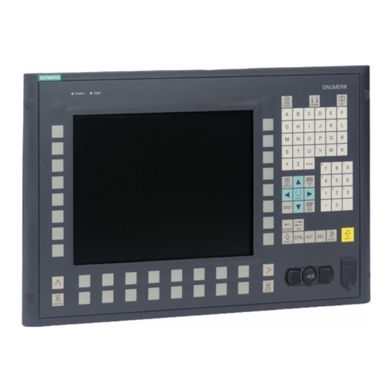
Page 89: Description
Description The SINUMERIK OP 010 operator panel front has a 10.4" TFT color display with a resolution of 640 x 480 pixels (VGA) and features a 62-key membrane keyboard (with 8 + 4 horizontal softkeys and 8 vertical softkeys) that has been optimized for programming parts programs. It is fixed from the rear using special clamps that are included in the delivery scope. - Page 90 Description Operator panel front: OP 010 Manual, 07/2018, A5E36371538B...
-
Page 91: Operator Control And Display Elements
Operator control and display elements View ① Alphabetic key group ② Numeric key group ③ Control key group ④ Hotkey group ⑤ Cursor key group ⑥ Front USB interface ⑦ Menu select key ⑧ Menu forward key ⑨ Machine area button ⑩... -
Page 92: Keyboard
Operator control and display elements 3.2 Keyboard Keyboard Keyboard Several keys and keypads are arranged on the OP 010 operator panel front: ● The alphabetic key group contains the letters A, ..., Z on two levels, arranged in accordance with programming requirements. ●... -
Page 93: Screen Saver
Operator control and display elements 3.3 Screen saver Function corresponds to the Function corresponds to the PC key function PC key function Page down Delete Cursor up Insert Cursor left Enter Cursor right Cursor down 5 (in numeric key group) A, ..., Z <Shift>... - Page 94 Operator control and display elements 3.3 Screen saver Operator panel front: OP 010 Manual, 07/2018, A5E36371538B...
-
Page 95: Interfaces
Interfaces This operator panel front has the following interfaces: Front USB 1.1 Full Speed (socket, type A) for connecting an external keyboard, mouse and USB flash drive (see View (Page 91)). Note Note that the electromagnetic compatibility of commercially available peripheral devices operated via the USB interface is usually rated for office use only. - Page 96 Interfaces Pin assignment For more detailed information, see "General information and networking", Chapter: "Connecting". Operator panel front: OP 010 Manual, 07/2018, A5E36371538B...
-
Page 97: Installation
Installation Preparation for mounting Table 5-1 Dimensions of the mounting opening Width (mm) Height (mm) Thanks to the tension jacks on the OP 010, drill-holes or screw holes are not needed. This retaining method also enables the IP65 degree of protection (but only in conjunction with a circumferential seal and when the protective USB cap is fitted). -
Page 98: Assembling An Op 010 And A Pcu
Installation 5.2 Assembling an OP 010 and a PCU Figure 5-2 Dimension sheet for attaching the PCU to the OP 010 operator panel front Assembling an OP 010 and a PCU When combining an OP 010 and PCU, it is advisable to assemble them prior to installation in an assembly panel. - Page 99 Installation 5.2 Assembling an OP 010 and a PCU Requirement The PCU must now be bolted to the mounting brackets prior to assembly (if this has not already been done). See Section in the “PCU 50.5” manual under “Assembly" → "Assembly of PCU and operator panel front (standard mounting)"...
- Page 100 Installation 5.2 Assembling an OP 010 and a PCU ① I/O USB cable K1 ② Display cable K2 Figure 5-4 (A) Assembling PCU and OP 010 ① I/O / USB cable K1 ② Display cable K2 Figure 5-5 (B) Correct connection of I/O-USB and display cables to the PCU Operator panel front: OP 010 Manual, 07/2018, A5E36371538B...
-
Page 101: Mounting On The Mounting Wall
Installation 5.3 Mounting on the mounting wall ① Knurled screw Figure 5-6 (C) OP 010 and PCU after assembly Note The OP 010 and TCU assembly is similar to that for a PCU. Mounting on the mounting wall The clearance at the rear of the PCU/TCU must be at least 10 mm to ensure sufficient ventilation (see Figure 5-1 Dimension sheet for installing the OP 010 operator panel front (Page 97)). -
Page 102: Softkey Labeling
(Page 105)). Note Use the "Arial" font to format text. This font is comparable to the "Univers S57" font, used by Siemens for the key labeling. Procedure 1. Letter the mat side of the film using a laser printer. -
Page 103: Technical Data
Technical data Safety Safety class III; PELV according to EN 50178 Degree of protection accord‐ Front side IP65 ing to EN 60529 Rear side IP00 Approvals CE / cULus Electrical data Power consumption (without Typically approx. 4 W load at USB interface) Max. - Page 104 Technical data Operator panel front: OP 010 Manual, 07/2018, A5E36371538B...
-
Page 105: Spare Parts
Spare parts Overview The following diagram shows the OP 010 operator panel front dismantled into its individual parts. Figure 7-1 Individual parts for the OP 010 operator panel front The components listed in the following table with an article number are available as spare parts. ①... -
Page 106: Replacement
Spare parts 7.2 Replacement The dimensions for creating slide-in labels from the foil for labeling the vertical softkeys can be seen in the following diagram. Figure 7-2 Dimensions for slide-in labels Note The symbols for the four softkeys for navigation in the menus shown in the figure are not contained in the blank film. - Page 107 Spare parts 7.2 Replacement USB cap / tension jack The replacement of the USB sealing cap and tension jacks will not be described since it is simple and self-explanatory. Film labels The procedure for replacement is as described in Chapter "Softkey labeling". Operator panel front When replacing the operator panel front, the previous display and keyboard controller can continue to be used.
- Page 108 Spare parts 7.2 Replacement Procedure ① Mounting slots for PCU lugs ② Display support plate ③ Enclosure screws ④ Slots for inserting softkey labeling strips ⑤ Cover plate for keyboard controller connections ⑥ Display cable K1 (cable shown folded) ⑦ IO/USB cable K1 (cable shown folded) Figure 7-3 Rear of the OP 010...
- Page 109 Spare parts 7.2 Replacement 8. Lift USB interface and keyboard controller off the front plate. The interconnections may remain plugged. 9. Install the components into the new operator front panel in reverse order (procedure: see Note). Note Descriptions of how to disconnect and connect the membrane connectors can be found in chapter "General information and networking"...
- Page 110 Spare parts 7.2 Replacement Operator panel front: OP 010 Manual, 07/2018, A5E36371538B...
-
Page 111: Index
Index Faults when booting, 86 Film labels OP 010, 107 Front USB interface Backup battery OP 010, 89, 91 Connection conditions, 15 Boot server, 81 Heat dissipation Means of heat dissipation, 18 Calibrate touch panel, HT 8 HT 8, 58 Calibrate, 58 TCU, 59 Rotary coding switch, 56... - Page 112 Index Key symbols, 92 Keypads, 92 Mounting opening, 97 Power consumption, 103 User authorization, 39, 75 Slide-in labels, 106 User interface TFT flat screen, 89 Connection conditions, 11 Tightening torques, 103 VGA resolution, 89 Validity Manual, 36 VGA resolution Potential equalization, 13 OP 010, 89 Protective separation Connection conditions, 11...
Need help?
Do you have a question about the SINUMERIK 840D sl OP 010 and is the answer not in the manual?
Questions and answers