Fortinet FortiSwitch FortiSwitch-5003 System Manual
Backplane interface switching
Hide thumbs
Also See for FortiSwitch FortiSwitch-5003:
- Fabric and base backplane communications manual (128 pages) ,
- Hardware manual (97 pages) ,
- Introduction manual (77 pages)
Table of Contents
Advertisement
Quick Links
A detailed guide to the features and capabilities of the FortiSwitch-5003 System. This FortiSwitch-5003 System
Guide describes FortiSwitch-5003 hardware features, how to install the FortiSwitch-5003 module in a
FortiGate-5000 series chassis, and contains troubleshooting information to help you diagnose and fix problems.
The most recent versions of this and all FortiGate-5000 series documents are available from the
page of the
Fortinet Technical Documentation
Visit
http://support.fortinet.com
FortiSwitch-5003 System Guide
01-30000-0384-20070201
web site (http://docs.forticare.com).
to register your FortiSwitch-5003 system. By registering you can receive product
updates, technical support, and FortiGuard services.
www.fortinet.com
S y s t e m G u i d e
FortiSwitch-5003
FortiGate-5000
Advertisement
Table of Contents

Related Manuals for Fortinet FortiSwitch FortiSwitch-5003


Summary of Contents for Fortinet FortiSwitch FortiSwitch-5003
- Page 1 FortiGate-5000 series chassis, and contains troubleshooting information to help you diagnose and fix problems. The most recent versions of this and all FortiGate-5000 series documents are available from the page of the Fortinet Technical Documentation Visit http://support.fortinet.com updates, technical support, and FortiGuard services.
-
Page 2: Warnings And Cautions
Some FortiGate-5000 series components may overload your supply circuit and impact your overcurrent protection and supply wiring. Refer to nameplate ratings to address this concern. • Make sure all FortiGate-5000 series components have reliable grounding. Fortinet recommends direct connections to the branch circuit. •... -
Page 3: Table Of Contents
Troubleshooting ... 15 FortiSwitch-5003 does not startup ... 15 For more information... 17 Fortinet documentation... 17 Fortinet Tools and Documentation CD ... 17 Fortinet Knowledge Center ... 17 Comments on Fortinet technical documentation ... 17 Customer service and technical support ... 17 Register your Fortinet product... - Page 4 Contents FortiSwitch-5003 System Guide 01-30000-0384-20070201...
-
Page 5: Fortiswitch-5003 Module
FortiSwitch-5003 module FortiSwitch-5003 module The FortiSwitch-5003 module provides base backplane interface switching for the FortiGate-5140 chassis and the FortiGate-5050 chassis. You can use this switching for data communication or HA heartbeat communication between the base backplane interfaces of FortiGate-5000 series modules installed in slots 3 and up in these chassis. -
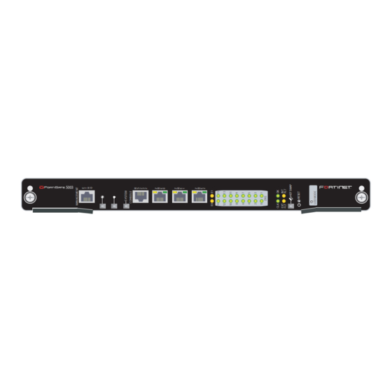
Page 6: Leds
Press this button to switch the ZRE LEDs to Link/Speed mode. In Link/Speed mode the ZRE LEDs use a solid color to indicate a link. The color of the LED indicates the speed of the link. -
Page 7: About The Zre Network Activity Leds
Table 1: FortiSwitch-5003 module front panel LEDs and switches (Continued) EXT FLT INT FLT Hot Swap Reset switch About the ZRE network activity LEDs The ZRE network activity LEDs show links and network activity for the interfaces and connections listed in Figure 2: FortiSwitch-5003 ZRE network activity LEDs... -
Page 8: Connectors
Base backplane communications Connectors Base backplane communications Table 3 lists and describes the FortiSwitch-5003 front panel connectors. Table 3: FortiSwitch-5003 connectors Connector Type Speed Protocol ETH0 RJ-45 100Base-T Ethernet CONSOLE RJ-45 9600 bps RS-232 serial ZRE0, RJ-45 10/100/1000 Ethernet Base-T ZRE1, ZRE2 This section provides a brief introduction to using FortiSwitch-5003 modules for... - Page 9 FortiSwitch-5003 module In a single chassis, more than one cluster can use the same base backplane interface for HA heartbeat communication. To separate heartbeat communication for multiple clusters on the same base backplane interface, configure a different HA group name and password for each cluster. In a single chassis, you can also use the same base backplane interface for data and HA heartbeat communication.
- Page 10 Base backplane communications FortiSwitch-5003 module FortiSwitch-5003 System Guide 01-30000-0384-20070201...
-
Page 11: Hardware Installation
1 or slot 2 of a FortiGate-5140 or FortiGate-5050 chassis. The FortiSwitch-5003 module left extraction lever contacts to a hidden power switch. The module must be fully installed in a chassis slot and this extraction lever must be closed and locked for the FortiSwitch-5003 module to receive power and operate normally. - Page 12 FortiSwitch-5003 module into a slot in a chassis only and should not be used for handling the module. If the extraction levers become bent or damaged the FortiSwitch-5003 module may not align correctly in the chassis slot and the left extraction lever may not activate the power switch. To complete this procedure, you need: •...
- Page 13 Hardware installation Turn both extraction levers to their fully-closed positions. The extraction levers should hook into the sides of the chassis slot. Closing the extraction levers draws the FortiSwitch-5003 module into place in the chassis slot and into contact with the chassis backplane. The FortiSwitch-5003 front panel should be in contact with the chassis front panel.
-
Page 14: Removing A Fortiswitch-5003 Module From A Chassis
FortiSwitch-5003 module into a slot in a chassis only and should not be used for handling the module. If the extraction levers become bent or damaged the FortiSwitch-5003 module may not align correctly in the chassis slot and the left extraction lever may not activate the power switch. To complete this procedure, you need: •... -
Page 15: Troubleshooting
Positioning of FortiSwitch-5003 extraction levers may prevent a FortiSwitch-5003 module for starting up correctly. All chassis: left extraction lever not contacting power switch The left extraction lever activates the FortiSwitch-5003 module power switch. Figure 4: Location of FortiSwitch-5003 power switch Alignment... - Page 16 Troubleshooting Hardware installation FortiSwitch-5003 System Guide 01-30000-0384-20070201...
-
Page 17: For More Information
Fortinet Tools and Documentation CD All Fortinet documentation is available from the Fortinet Tools and Documentation CD shipped with your Fortinet product. The documents on this CD are current for your product at shipping time. For the latest versions of all Fortinet documentation see the Fortinet Technical Documentation web site at http://docs.forticare.com. - Page 18 © Copyright 2007 Fortinet, Inc. All rights reserved. No part of this publication including text, examples, diagrams or illustrations may be reproduced, transmitted, or translated in any form or by any means, electronic, mechanical, manual, optical or otherwise, for any purpose, without prior written permission of Fortinet, Inc.
Need help?
Do you have a question about the FortiSwitch FortiSwitch-5003 and is the answer not in the manual?
Questions and answers