
Related Manuals for Mircom TX3 Series


Summary of Contents for Mircom TX3 Series
- Page 1 TX3 Series Telephone Access System Programming Manual TX3 Telephone Access System Programming Manual Version 2.7 LT-979 Copyright October 2018...
- Page 2 Copyright October 2018 Mircom Inc. All rights reserved. Mircom Telephone Access System Programming Manual Version 2.7 Microsoft, MS-DOS, Windows, and Windows 2000/NT/XP/Vista/7/8/10 are either registered trademarks or trademarks of Microsoft Corporation in the United States and/or other countries. Mircom 25 Interchange Way...
-
Page 3: Table Of Contents
Contents Introduction TX3 Systems Features Warranty and Special Notices About This Manual Contact Us Viewing Resident List Configuration Keypad Navigation Beginning Configuration Accessing the Operation Menu Viewing Configuration Information Viewing the Time and Date Configuration Menu System Option Database Menu Schedule Menu 2.10 Holidays Menu... -
Page 4: Introduction
Configuration must be performed by a qualified technician and must adhere to the standards and special notices set by the local regulatory bodies. Note: Mircom periodically updates panel firmware and Configurator Software to add features and correct any minor inconsistencies. For information about the latest firmware or software visit the Mircom website at www.mircom.com. -
Page 5: Tx3 Systems
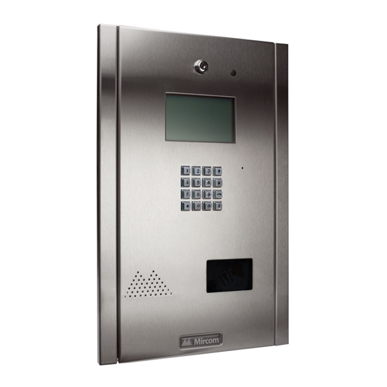
Introduction TX3 Systems The Mircom's TX3 series of telephone access systems provide high quality two- way communication between residents and their visitors in a multi-unit dwelling establishment. The basic TX3 system consists of the TX3 Entry Panel and depending on the application, may be integrated with a combination of Mircom Elevator Restriction Units and Card Access Units. -
Page 6: Warranty And Special Notices
About This Manual This manual provides comprehensive information on the configuration of the TX3 Series Telephone Access System. Tasks are described in the order that they are likely to be performed. TX3 Telephone Access System Programming Manual Version 2.7... -
Page 7: Contact Us
• TX3-1000-8CH-A • TX3-2000-8CH-A • TX3-2000-8K-A 1.4.1 Additional Documentation For additional documentation, see the following Mircom literature: • LT-995 TX3-CX Touch Screen Administrators Guide • LT-968 TX3 Telephone Access System User’s Guide Contact Us 1.5.1 Canada and USA Phone: 905-660-4655... -
Page 8: Viewing Resident List
Introduction Viewing Resident List The TX3 Entry Panel LCD shows a scrollable view of the resident names and dial codes. The LCD comes in a four or eight line LCD handset version. A paper version of the resident list is also available. To view the resident list Press the up or down arrow keys on the Entry Panel keypad to scroll through the list line by line. -
Page 9: Configuration
Configuration This chapter provides detailed information about the TX3 Telephone Access System configurable functions. This chapter explains • Keypad Navigation • Beginning Configuration • Accessing the Operation Menu • Viewing Configuration Information • Viewing the Time and Date • Configuration Menu •... -
Page 10: Keypad Navigation
Configuration Keypad Navigation Figure 1 shows how to use the keypad when in CONFIGURATION MODE. Note that the keypad buttons can have different functions when creating resident entries. Refer to 2.8.1 Adding a New Record and Table 1: List of Screens for more information. -
Page 11: Accessing The Operation Menu
Configuration To enter configuration mode Press The main menu appears with four choices. Main Menu 1 Configuration 2 Operation 3 View Cfg Info 4 View time & dat To access the Operation menu see section 2.3. To access the View Configuration Information menu see section 2.4. To view the time and date see section 2.5. - Page 12 Configuration To access the operation menu Press 9 9 9 9. The configuration information appears. Main Menu 1 Configuration 2 Operation 3 View Cfg Info 4 View time & dat Press the (scroll down) to “Operation”. Press the telephone key. Enter your passcode, then press the telephone key.
-
Page 13: Viewing Configuration Information
Configuration If recent events have occurred, such as, entering of dial codes and the opening of the main door, this information appears along with the date and time as follows. User log info Log: 190 of 5000 Event: Call Connect Acc pt: N/A Acc Code: D20 Jan 15 2010... - Page 14 Configuration • Firmware Version • Panel Type (for example, telephone access or card access) • Model (for example, 200 names) • Last Modified • Cfg tool used (for example, Configurator or front panel) • Panel ID • RS485 Address • IP Address To view configuration information, you must first enter the configuration mode.
-
Page 15: Viewing The Time And Date
Configuration Viewing the Time and Date To view time and date Press 9 9 9 9. The configuration information appears. Main Menu 1 Configuration 2 Operation 3 View Cfg Info 4 View time & dat Press the (scroll down) to “View time & date”. Press the telephone key. -
Page 16: System Option
Configuration System Option Selecting “System Option” from the Configuration Menu gives you the following configuration options: • Tone/Pulse mode • Line Type • Main Door DTMF • Aux Door DTMF • Main door timer • Aux door timer • Talk timer •... - Page 17 Configuration 2.7.1 Tone/Pulse mode Note: Although this option appears on the front panel, it is not configurable. The telephone always operates in tone mode. Pulse dialing is not available. To access the Tone/Pulse option screen Press the arrow key to scroll to “Tone/Pulse mode” and press the telephone key.
- Page 18 Configuration 2.7.3 Main Door DTMF The Main Door DTMF function defines the key the resident presses to open the main door. The default key is 9. To define the Main Door DTMF key Press the arrow key to scroll to “Main Door DTMF” and press the telephone key.
- Page 19 Configuration Use the * key to select the number and the telephone (enter) key to confirm the DTMF code. Valid numbers are 1 to 9, * or #. Note: Do not select 4 (this is used to refuse entry or disconnect). Do not use the same number for the main door, auxiliary door, and call waiting (call waiting works on NSL systems only).
- Page 20 Configuration To set the Auxiliary Door Timer Press the arrow key to scroll to auxiliary “Door Timer” and press the telephone key. The Auxiliary Door Timer selection entry appears. Auxiliary Door Timer [ 010 ] Use the up or down keys to select the number of seconds. Valid programmable time is 1 to 60 seconds.
- Page 21 Press the arrow key to scroll to “Welcome Message” and press the telephone (enter) key. The welcome message appears. Enter Msg Line - 1 MIRCOM TX3 #1 Press the up arrow key to scroll to the next message line (Line-2) and scroll up again for next message (Line-3).
- Page 22 Configuration To enable the guard phone Press the arrow key to scroll to “Guard Phone” and press the telephone (enter) key. The Guard Phone selection appears. Guard Phone [ ] Guard Phone [ x ] No Guard Phone Press the up arrow key to see all 3 lines as shown above. The default is no guard phone.
- Page 23 Configuration Use the up and down arrow keys to select the schedule and press the telephone (enter) key to accept. Note: The configurator software program defines up to 64 schedules. Press info key to return to previous menu. 2.7.12 Unlock Schedule The Unlock Schedule function lets you define when residents can grant access to a visitor according to the day and/or time.
- Page 24 Configuration To set the Keycode Schedule Press the arrow key to scroll to “Keycode Sch” and press the telephone (enter) key. The Keycode Schedule selection appears. Unlock Sch 0 Always 1 Never 2 Weekdays 3 Weekend 4 Evenings 5 Holidays Press the up and down arrow keys to scroll through the schedules as shown above.
- Page 25 Configuration The default call wait key is 2 and the available range is 1 to 9. Once selection is made using the up/down selection keys, press the (enter) key to accept. Note: Do not select 4. This is used to refuse entry or disconnect. Press info key to return to previous menu.
- Page 26 Configuration Press the telephone (enter) key to accept. Press info key to return to the previous menu. 2.7.17 Postal Usage The “Postal Usage” function lets you define the maximum daily usage for the postal lock. The range is 1 to 254 and the default is 4. For unlimited usage set the value to 255.
- Page 27 Configuration 2.7.19 Daylight Saving The “Daylight Saving” function lets you set the daylight savings time for the Entry Panel LCU. When active this feature automatically adjusts the time by one hour in the spring and the fall each year. To set the Daylight Saving function Scroll the arrow to “Daylight Saving”...
- Page 28 Configuration 2.7.21 Elevator Rest Timer The “Elevator Restriction Timer” function lets you define the elevator access time. The elevator restriction cabinet houses up to 96 Form C type relay contacts. These relay contacts are normally connected to the input circuits of the elevator manufacturer’s button controller.
- Page 29 Configuration Press the up and down arrow keys to scroll through the numbers. The range is 1-15 and the default is 11. Press the telephone (enter) key to accept. Press info key to return to previous menu. 2.7.23 MIC Volume The “Microphone Volume”...
- Page 30 Configuration To set the “Select Font Option” function Press the arrow key to scroll to “Select Font Option” and press the telephone (enter) key. The “Select Font Option” selection appears. Select Font [ x ] Fixed system [ ] Lucida console [ ] Courier bold [ ] Courier reg [ ] Raize...
- Page 31 Configuration 2.7.26 Auto Unlock Schedule The Auto Unlock Schedule function lets you keep the door unlocked for the duration of the selected schedule. The door locks when the schedule ends. To set the Auto Unlock Schedule Press the arrow key to scroll to “Auto Unlock Sch” and press the telephone (enter) key.
-
Page 32: Database Menu
Configuration 2.7.28 Handset The handset option lets you specify if there is a handset connected to your panel. The default setting is “Hands-free” (that is, no handset). To set the Handset option Press the arrow key to scroll to “Handset” and press the telephone key. The Handset selection appears. - Page 33 Configuration 2.8.1 Adding a New Record Table 3 describes the information for adding new resident information. Use the information in Table 3 to help you add new records. To enter a resident From the configuration menu, select the database menu. The database selection appears.
- Page 34 Configuration Note: If you accidentally enter the wrong character while configuring an apartment number, press * once to backspace. For example, to enter the apartment number “23B”, a. Press “2” once for the “2”, and then wait for the cursor to advance. b.
- Page 35 Configuration For Resident Telephone Number Entry Only press to add a comma (generates a 1 second delay when dialing) press to add a semi-colon (generates a 3 second delay when dialing) press to delete Figure 4. Keypad commands for entering a resident’s telephone number.
- Page 36 Configuration Table 1: List of Screens Database Menu Explanation/Description System System Enter Apt# Enter the resident’s apartment number (up to 8 digits). [_ _ _ _] Enter Dial Code Enter the resident’s dial code (up to 4 digits). _ _ _ _ Main Door sec.
- Page 37 Configuration Table 1: List of Screens Enter Elev Rest Code Enter the elevator restriction relay number for the resident. [_ _] Hide Display This feature turns the resident information display ON or OFF. When OFF the resident’s information is only [x] Display displayed in configuration mode.
- Page 38 Configuration 2.8.4 Editing Records To edit a record Select “Edit Record” and use the up/down key to scroll through the residents. Press the telephone button to select the resident’s name for editing. 1212>Smith 1213 Jones 1214 Hath 1215 Johnson Use the down arrow key to scroll down the list of fields, such as Apartment number, Resident name, Dial code Keyless code, relay code, telephone number, etc.
- Page 39 Configuration When the warning appears “Delete Record? Y. Press the telephone key to accept or the info key to cancel. Once the record has been deleted, the screen will return to the Delete Record function. At this point you may delete other records or press the info key to return to the configuration menu.
- Page 40 Configuration Table 3 describes the information you will need to auto program the panel. Table 3: Auto Programming Information Programming Menu Explanation/Description System System Enter the total number of residents to auto Number of Records program (4 digits). Scroll up or down to the desired number, then press enter (telephone [____] key).
- Page 41 Configuration Press the telephone (enter) key to accept. The next screen will ask for resident name. Enter one of the resident names using the alphanumeric keypad. Enter Resident Name Press the telephone (enter) key to accept. The next screen will ask for the resident’s dial code.
-
Page 42: Schedule Menu
Configuration Schedule Menu The schedule menu lets you set up a timetable to establish when certain panel functions are permitted to occur, such as when calls to residents are allowed, when residents can grant access to a visitor or when the postal lock can be used. These schedules are designated and listed by name, and are available for selection wherever it is necessary to invoke access permission. -
Page 43: Holidays Menu
Configuration To edit or delete a schedule Select Edit or Delete. A list of all the schedules appears. Press the arrow keys to scroll to the schedule you would like to edit or delete. Press the telephone (enter) key to accept. Press info key to return to previous menu. -
Page 44: Set Time & Date
Configuration Press the telephone (enter) key to accept. Press the arrow keys to scroll to the item you want to edit for the holiday (that is, “Label”, “Start Time/Date”, “End Time/Date”, or “Repeat Annually“), and then press the telephone (enter) key. ---New Year 1 Label 2 Start Time/Date... -
Page 45: Factory Default
Configuration Use the up and down arrow keys to change the time and date. Press the enter (telephone) key to save the changes. 2.12 Factory Default The “Factory Default” selection lets you apply the factory default settings for the telephone access system. Note: Selecting the Factory Default does not delete any resident information. - Page 46 Configuration To define inputs Press the arrow key to scroll to Inputs, and press the enter (telephone) key. The “Input Types” selection appears. Input Types 1 Postal lock 2 Fire P Override 3 Door Sense 4 GP Input 3 5 GP Input 4 Press the arrow key to scroll to the input you wish to configure and press the telephone (enter) key.
-
Page 47: Correlations
Configuration To define outputs Press the arrow key to scroll to Outputs, and press the enter (telephone) key. The Output selection appears. Output Types 1 Main Door lock 2 Aux Door lock 3 GP Output 3 4 GP Output 4 Press the arrow key to scroll to the output you wish to configure and press the telephone (enter) key. - Page 48 Configuration To make a correlation Select Add. The “Event” selection appears. Event Type [ X ]Input Active ] Call Started ] Call Ended ] Call Connected ] Access Granted ] Access Denied ] System Normal Press the arrow key to scroll to a specific type of input and press the telephone (enter) key.
-
Page 49: Changing Passcodes
Configuration Press the arrow key to scroll to a specific output and press the telephone (enter) key. The “Schedule” selection appears Select Schedule 0 Always Press the arrow key to select a specific schedule and press the telephone (enter) key. The “Correlation Timer” entry appears Corr Timer [ 001] Press the arrow key to specify the duration for the correlation and press the... - Page 50 (enter) key to accept. Enter the new passcode. It can be up to 10 digits long. Note: If you forgot the new passcode, call Mircom’s Technical Support Department. See Technical Support contact information in Section 1.5). Press the telephone (enter) key to accept. The “Enter New Passcode” entry appears.
-
Page 51: Test Lcd
Configuration 2.16 Test LCD The Test LCD selection lets you view all 255 character lines. To test the LCD Press the arrow to scroll to “Test LCD” in the main configuration menu and press the enter (telephone) key. The “Test LCD” menu appears. Press the arrow keys to scroll through the character lines. -
Page 52: Warranty And Warning Information
Companies are not to be used as a fire, alarm, or life-safety system. NOTE TO INSTALLERS: All Mircom Systems have been carefully designed to be as effective as possible. However, there are circumstances where they may not provide protection. Some reasons for system failure include the following. - Page 53 Best practices and local authority having jurisdiction determine the frequency and type of testing that is required at a minimum. Mircom System may not function properly, and the occurrence of other system failures identified below may not be minimized, if the periodic testing and maintenance of Mircom Systems is not completed with diligence and as required.
- Page 54 Moreover, some Mircom Systems do not have a battery monitor that would alert the user in the event that the battery is nearing its end of life. Regular testing and replacements are vital for ensuring that the batteries function as expected, whether or not a device has a low-battery monitor.
- Page 55 Component Failure. Although every effort has been made to make this Mircom System as reliable as possible, the system may fail to function as intended due to the failure of a component. Integrated Products. Mircom System might not function as intended if it is connected to a non-Mircom product or to a Mircom product that is deemed non-compatible with a particular Mircom System.
- Page 56 Warranty and Warning Information Warranty Purchase of all Mircom products is governed by: https://www.mircom.com/product-warranty https://www.mircom.com/purchase-terms-and-conditions https://www.mircom.com/software-license-terms-and-conditions TX3 Telephone Access System Programming Manual Version 2.7 LT-979 Copyright 2018...
-
Page 57: Special Notices
Special Notices Product Model Number: TX3 AC REN (U.S.): 0.0B AC REN (CANADA): 0.0 Complies With Federal Communications Commission (FCC): • TIA-968-A Technical requirement for connection of equipment tot he telephone network. • CFR 47, Part 15, Subpart B, Class B •... - Page 58 Special Notices Repairs to certified equipment should be made by an authorized Canadian maintenance facility designated by the supplier. Any repairs or alteration made by the user to this equipment, or equipment malfunctions, may give the telecommunications company cause to request the user to disconnect the equipment.
- Page 59 Contact your telephone company if you have any questions about your telephone line. In the event repairs are ever needed on the Communicator, they should be performed by Mircom or an authorized representative of Mircom. For information contact Mircom at the address and telephone numbers in paragraph 1.5.
- Page 60 Equipment Failure If trouble is experienced with the TX3 Telephone/Card Access System, for repair or warranty information, please contact Mircom using the numbers in paragraph 1.5. If the equipment is causing harm to the telephone network, the telephone company may request that you disconnect the equipment until the problem is resolved.
Need help?
Do you have a question about the TX3 Series and is the answer not in the manual?
Questions and answers