Table of Contents
Advertisement
1.
SAFETY PRECAUTIONS AND WARNINGS .............................................. 1
2.
GENERAL INFORMATION .......................................................................... 2
2.1
2.2
2.3
2.4
2.5
2.6
2.7
3.
USING THE SCAN TOOL ............................................................................ 10
3.1
3.2
3.3
3.4
3.5
3.6
3.7
3.8
3.9
V
4.
OBD II DIAGNOSTICS ................................................................................ 24
4.1
4.2
4.3
4.4
V
4.5
4.6
V
4.7
5.
READY TEST ................................................................................................ 41
5.1
5.2
5.3
6.
WARRANTY AND SERVICE ...................................................................... 46
6.1
6.2
Table of Contents
.................................................................................... 6
.................................................................................... 10
.......................................................................................... 11
.................................................................................................. 12
........................................................................................................ 12
............................................................................................ 12
......................................................................................................... 20
.................................................................................. 21
......................................................................................... 25
.......................................................................................... 28
.................................................................................................. 30
V
................................................................................ 46
(OBD) II ............................................................. 2
) ........................................................ 2
.................................................................... 4
......................................................... 5
.................................................................... 7
............................................................................. 11
........................................................................ 11
.................................................................... 22
................................................................. 31
......................................................... 32
.............................................................. 38
......................................................................... 40
............................................................................ 41
........................................................................... 42
.............................................................. 44
................................................................ 46
(DLC) .................................... 3
Advertisement
Table of Contents

Related Manuals for Autel AutoLink AL319


Summary of Contents for Autel AutoLink AL319
-
Page 1: Table Of Contents
Table of Contents SAFETY PRECAUTIONS AND WARNINGS ..........1 GENERAL INFORMATION ................2 (OBD) II ............. 2 OARD IAGNOSTICS (DTC ) ............2 IAGNOSTIC ROUBLE ODES (DLC) ........3 OCATION OF THE ONNECTOR OBD II R ..............4 EADINESS ONITORS OBD II M ............ -
Page 2: Safety Precautions And Warnings
1. Safety Precautions and Warnings To prevent personal injury or damage to vehicles and/or the scan tool, read this instruction manual first and observe the following safety precautions at a minimum whenever working on a vehicle: Always perform automotive testing in a safe environment. ... -
Page 3: General Information
2. General Information 2.1 On-Board Diagnostics (OBD) II The first generation of On-Board Diagnostics (called OBD I) was developed by the California Air Resources Board (ARB) and implemented in 1988 to monitor some of the emission control components on vehicles. As technology evolved and the desire to improve the On-Board Diagnostic system increased, a new generation of On-Board Diagnostic system was developed. -
Page 4: Location Of The Data Link Connector (Dlc)
DTC Example 0 2 0 2 Systems Identifying specific B=Body malfunctioning C=Chassis section of the P=Powertrain systems U=Network Code Type Sub-systems Generic (SAE): 1= Fuel and Air Metering P0, P2, P34-P39 2= Fuel and Air Metering B0, B3 3= Ignition System or Engine C0, C3 Misfire Identifying specific... -
Page 5: Obd Ii Readiness Monitors
2.4 OBD II Readiness Monitors An important part of a vehicle’s OBD II system is the Readiness Monitors, which are indicators used to find out if all of the emissions components have been evaluated by the OBD II system. They are running periodic tests on specific systems and components to ensure that they are performing within allowable limits. -
Page 6: Obd Ii Monitor Readiness Status
monitors are termed non-continuous monitors. For different ignition type engines, the available monitors are different too. The following monitors are to be used for spark ignition engines only: EGR System O2 Sensors Catalyst Evaporative System O2 Sensor Heater Secondary Air Heated Catalyst The following monitors are to be used for compression ignition engines only:... -
Page 7: Obd Ii Definitions
including erasing of diagnostic trouble codes (DTCs) with a scan tool or a disconnected battery, can result in Readiness Monitors being set to “Not Ready”. Since the three continuous monitors are constantly evaluating, they will be reported as “Ready” all of the time. If testing of a particular supported non-continuous monitor has not been completed, the monitor status will be reported as “Not Complete”... -
Page 8: Obd Ii Modes Of Operation
of the enabling criteria. Drive cycles vary among vehicles and for each monitor in any particular vehicle. OBD II Drive Cycle -- A specific mode of vehicle operation that provides conditions required to set all the readiness monitors applicable to the vehicle to the “Ready” condition. The purpose of completing an OBD II drive cycle is to force the vehicle to run its onboard diagnostics. - Page 9 Mode $02 - Displays Freeze Frame data. Same data as in mode 1, but it was captured and stored when a malfunction occurred and a DTC was set. Some of the PIDs for mode one are not implemented in this mode. Mode $03 - Displays the type of powertrain or emission related DTCs stored by a 5 digit code identifying the faults.
- Page 10 used by service technicians to verify repair was performed properly and after clearing diagnostic trouble codes. Mode $08 - This Special Control Mode requests control of the on-board system, test, or component bi-directionally (where applicable). This mode is manufacturer specific. Mode $09 - Reports vehicle information.
-
Page 11: Using The Scan Tool
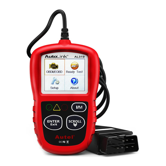
3. Using the Scan Tool 3.1 Tool Description ① OBD II CONNECTOR – Connects the scan tool to the vehicle’s Data Link Connector (DLC). ② LCD DISPLAY – Indicates test results. GREEN LED – Indicates that engine systems are running ③... -
Page 12: Specifications
YELLOW LED – Indicates there is a possible problem. A ④ “Pending” DTC is present and/or some of the vehicle’s emission monitors have not run their diagnostic testing. RED LED – Indicates there is a problem in one or more of ⑤... -
Page 13: Keyboard
Characters used to help navigate the scan tool are: “#” – Identifies the control module number from which data is retrieved. 2) “Pd” – Identifies a pending DTC when viewing DTCs. 3.5 Keyboard No solvents such as alcohol are allowed to clean the keypad or display. Use a mild nonabrasive detergent and a soft cotton cloth. - Page 14 When the scan tool is powered on, it displays a Main Screen. (Figure 3.1) Figure 3.1 From the Main Screen: Use the SCROLL button to select Setup, and press the ENTER/Exit button. Follow the instructions to make adjustments and settings as described in the above setup options. (Figure 3.2) System Setup Language...
- Page 15 Use the SCROLL button to select the desired language and press the ENTER/Exit button to save your selection and return to previous screen. (Figure 3.3) Language English Franç ais Españ ol Deutsch Figure 3.3 Configure Monitors From System Setup screen, use the SCROLL button to select Configure Monitors, and press the ENTER/Exit button.
- Page 16 flexible way to meet different standards, which allows the user to select 0, 1, 2, or 3 “not complete” monitors in test. Reset Factory Default From Configure Monitors screen, use the SCROLL button to select Reset Factory Default, and press the ENTER/Exit button. It will restore the default configuration settings in the Configure Monitors menu, and delete any customized settings.
- Page 17 This function allows you to turn on/off the build-in speaker for key pressing. The default setting is Beep On. From System Setup screen, use the SCROLL button to select Key Beep Set and press the ENTER/Exit button. From Key Beep Set menu, use the SCROLL button to select Beep ON or Beep OFF to turn on/off the beep.
- Page 18 Status Beep Set Beep ON Beep OFF Figure 3.7 Press the ENTER/Exit button to save your selection and return to previous menu. Tool Self-test The Tool Self-test function checks if the display, LED lamps and keyboard are working properly. A.
- Page 19 Look for missing spots in the red, green, blue, black and white LCD display. When completed, press the ENTER/Exit button to exit. Keyboard Test The Keyboard Test function verifies if the keys are functioning properly. Use the SCROLL button to select Keyboard Test from the Tool Self-test menu, and then press the ENTER/Exit button.
- Page 20 A PC or laptop with USB ports A USB cable Download the programs to be updated in www.autel.com your computer. Run the MaxiLink II Tool Kit in your computer. (Figure 3.11) Connect the scan tool to your computer through the USB cable provided.
-
Page 21: About
Figure 3.11 During the update procedure, the scan tool displays a message “Update Program. Please wait…”. When the update has finished, the scan tool will display a message “Program Update has been done!” Restart the scan tool to finish the whole update. NOTE: Please select the bin file to update the operating system. -
Page 22: Vehicle Coverage
The About function allows viewing of some important information such as serial number and software version number of the scanner. From Main Screen, use the SCROLL button to select About and press the ENTER/Exit button; wait for the About screen to appear. -
Page 23: Product Troubleshooting
For your vehicle to be OBD II compliant it must have a 16-pin DLC (Data Link Connector) under the dash and the Vehicle Emission Control Information Label must state that the vehicle is OBD II compliant. 3.10 Product Troubleshooting This part describes problems that you may encounter while using the scan tool. - Page 24 Run the LED Test in the System Setup menu. (See 3.7 System Setup). If the scan tool does not pass this test, there is a problem with the LED lamp. Please contact Autel Tech Support or your local selling agent.
-
Page 25: Obd Ii Diagnostics
4. OBD II Diagnostics When more than one vehicle control module is detected by the scan tool, you will be prompted to select the module where the data may be retrieved. The most often to be selected are the Power train Control Module [PCM] and Transmission Control Module [TCM]. -
Page 26: Reading Codes
7) View a summary of system status (MIL status, DTC counts, Monitor status) on screen. (Figure 4.1 ) Wait a few seconds or press any key for Diagnostic Menu (Figure 4.3) to come up. System Status Codes Found Ignition Type Spark Monitors N/A Monitors OK... - Page 27 the control module to illuminate the malfunction indicator light (MIL) when emission-related fault occurs. Pending Codes are also referred to as “maturing codes” or “continuous monitor codes”. They indicate problems that the control module has detected during the current or last driving cycle but are not considered serious yet.
- Page 28 Read Codes Stored Codes Pending Codes Permanent Codes Previous Menu Figure 4.4 If there is not any Diagnostic Trouble Code, the display indicates “No (pending) codes are stored in the module!” Wait a few seconds or press any key to return to previous screen.
-
Page 29: Erasing Codes
If retrieved DTCs contain any manufacturer specific or enhanced codes, a “Manufacturer specific codes are found! Press any key to select vehicle make!” message comes up prompting you to select vehicle manufacturer to view DTC definitions. Use SCROLL button to select manufacturer and then press ENTER/Exit button to confirm. - Page 30 This function is performed with key on engine off (KOEO). Do not start the engine. 1) Use the SCROLL button to select Erase Codes from Diagnostics Menu and press the ENTER/Exit button. (Figure 4.3) 2) A warning message comes up asking for your confirmation. Erase Codes Erase trouble codes! Are you sure?
-
Page 31: Live Data
If the codes are not cleared, then an “Erase Failure. Turn Key on with Engine off!” message appears. Erase Codes Erase Failure. Turn Key on with Engine Off! Press any key to con. Figure 4.9 4.3 Live Data The function allows viewing of live or real time PID data of vehicle’s computer module(s). -
Page 32: Viewing Freeze Frame Data
…………………View Data 1/3. Complete Data Set Unit of Measure Previous Menu Figure 4.11 4) View live PIDs on the screen. Use the SCROLL button for more PIDs if additional information is available on more than one page. Live Data DTC_CNT FUELSYS1 FUELSYS2 LOAD_PCT (%) -
Page 33: Retrieving I/M Readiness Status
(VSS) etc. This information will aid the technician by allowing the parameters to be duplicated for diagnostic and repair purposes. To view freeze frame data, use the SCROLL button to select View Freeze Frame from Diagnostic Menu and press the ENTER/Exit button. - Page 34 Some latest vehicle models may support two types of I/M Readiness tests: A. Since DTCs Cleared - indicates status of monitors since the DTCs are erased. This Drive Cycle - indicates status of monitors since the beginning of the current drive cycle. An I/M Readiness Status result of “NO”...
- Page 35 “OK” -- Indicates that a particular monitor being checked has completed its diagnostic testing. “INC” -- Indicates that a particular monitor being checked has not completed its diagnostic testing. “N/A” -- The monitor is not supported on the vehicle. The green, yellow and red LEDs provide a quick way to help you determine if a vehicle is ready for an Emission Test.
- Page 36 Test depends on the emission regulations and laws of your local area. NOTE: From the code retrieval procedure, determine the status of each Monitor. Take this information to an emissions professional to determine (based on your test results) if your vehicle is ready for an Emissions Test.
- Page 37 LED Light Audio Tone Beep Interval Green LED Two long beeps 5 seconds Yellow LED short, long, short beep 5 seconds Red LED Four short beeps 5 seconds After you have read the information, press ENTER/Exit to exit. The other buttons are disabled to prevent misoperation. B.
- Page 38 O2S -- O2 Sensors Monitor CAT -- Catalyst Monitor EVAP -- Evaporative System Monitor HTR -- O2 Sensor Heater Monitor AIR -- Secondary Air Monitor HCAT -- Heated Catalyst Monitor For compression ignition engines: ...
-
Page 39: Viewing Vehicle Information
…………..This Drive Cycle MIL Status Misfire Monitor Fuel System Mon Comp. Component Catalyst Mon Htd Catalyst Figure 4.17 6) The LEDs and audio tones corresponding to different monitor status will be activated as below. LED Light Audio Tone Beep Interval Green LED Two long beeps 2 minutes... - Page 40 Vehicle Info. Turn key on with engine off ! Press any key to con. Figure 4.18 3) Wait a few seconds while the scan tool reads vehicle information. Vehicle Info. Reading info… - Please Wait - Figure 4.19 If the vehicle does not support this mode, a message shows on the display warning that the mode is not supported.
-
Page 41: Exiting The Obd Ii Test
Cal. Verf. Number CVN1: BB BA A0 78 Figure 4.21 6) Select Previous Menu from the Vehicle Info screen, and press ENTER/Exit button to return to the previous menu. 4.7 Exiting the OBD II Test To exit OBD II test, use SCROLL button to select Previous Menu from Diagnostic Menu and press ENTER/Exit button. -
Page 42: Ready Test
5. Ready Test This function can be used as a convenient readiness test tool by automotive technicians to determine if the tested vehicle is ready for an emission test. By visual and audible indication, you will learn a vehicle’s monitors readiness. 5.1 General Information Repairs to the emissions-control systems of a 1996 or newer vehicle cause the vehicle’s computer (ECU) memory to be cleared. -
Page 43: Test Tool Application
5.2 Test Tool Application The purpose of this function is to indicate which of the vehicle’s monitors have run and completed their diagnosis and testing, and which ones have not yet run and completed testing and diagnosis of their designated sections of the vehicle’s emission system. All data shows on one screen, which provides a simple profile of vehicle at a glance, saving diagnosis time and improving technician productivity. - Page 44 Connect the scan tool to the vehicle’s DLC and erase the DTC(s) from the vehicle’s computer memory. (See 4.2 Erasing Codes) After the erase procedure is performed, status of most monitors will be changed. Leave the scan tool connected to the vehicle, and select Ready Test from Main Screen.
-
Page 45: Led And Tone Interpretation
IMPORTANT: If you are driving the vehicle to perform a drive cycle ALONE, please set the Status Beep On (See 3.7 System Setup). By listening to the beep, you will learn when the monitors have run and completed the diagnostic testing. NEVER try to drive and operate the scan tool at the same time! This function retrieves the real time data of emission-related monitoring systems readiness status. - Page 46 “OK” -- Indicates that a particular monitor being checked has completed its diagnostic testing. “INC” -- Indicates that a particular monitor being checked has not completed its diagnostic testing. “N/A” -- The monitor is not supported on the vehicle. The LED and audio tone indications are interpreted as below: LED Interpretation The green and red LEDs provide an easy way to check if emission-related monitoring systems complete their self-diagnostic...
-
Page 47: Warranty And Service
6. Warranty and Service 6.1 Limited One Year Warranty Autel warrants to its customers that this product will be free from all defects in materials and workmanship for a period of one (1) year from the date of the original purchase, subject to the following terms and...
Need help?
Do you have a question about the AutoLink AL319 and is the answer not in the manual?
Questions and answers