
Related Manuals for RabbitCore RCM3100 Series


Summary of Contents for RabbitCore RCM3100 Series
- Page 1 RabbitCore RCM3100 C-Programmable Module Getting Started Manual 019–0114 • 020601–A...
- Page 2 RabbitCore RCM3100 Getting Started Manual Part Number 019-0114 • 020601–A • Printed in U.S.A. ©2002 Z-World Inc. • All rights reserved. Z-World reserves the right to make changes and improvements to its products without providing notice. Trademarks Rabbit 2000 is a trademark of Rabbit Semiconductor.
-
Page 3: Table Of Contents
Table of Contents Chapter 1. Introduction & Overview 1.1 Rabbit 3000 Microprocessor ........................ 1 1.2 RCM3100 Series RabbitCore Modules....................2 1.2.1 Physical & Electrical Specifications ................... 3 1.3 Development Software......................... 4 1.4 How to Use This Manual ........................4 1.4.1 Additional Product Information ....................4 1.4.2 Additional Reference Information .................... - Page 4 Notice to Users Index Schematics RabbitCore RCM3100...
-
Page 5: Chapter 1. Introduction & Overview
Dynamic C software development system. This Development Kit contains a powerful RabbitCore module (the RCM3110) and Pro- totyping Board that will allow you to evaluate the Rabbit 3000 and to prototype circuits that interface to a Rabbit 3000 micropro- cessor. -
Page 6: Rcm3100 Series Rabbitcore Modules
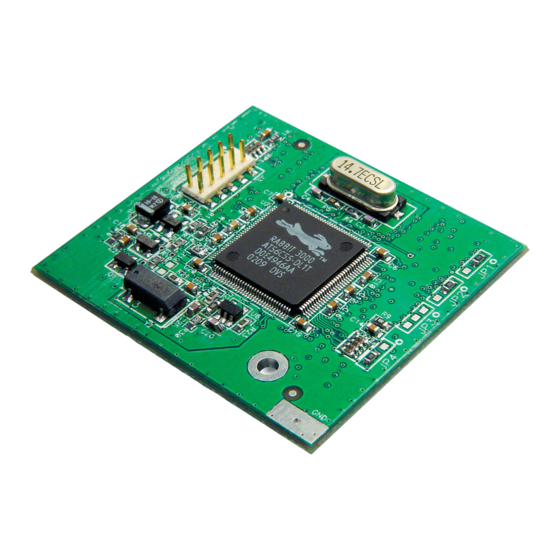
The RCM3100 series is equipped with 256K–512K flash memory and 128K–512K static RAM. There are two production models in the RCM3100 series. If the standard models do not serve your needs, other variations can be specified and ordered in production quantities. -
Page 7: Physical & Electrical Specifications
–40 C to 85 C, 5–95% humidity, noncondensing NOTE: For complete product specifications, see Appendix A in the RabbitCore RCM3100 User’s Manual. The RCM3100 modules have two 34-pin headers to which cables can be connected, or which can be plugged into matching sockets on a production device. The pinouts for these connectors are shown in Figure 1 below. -
Page 8: Development Software
This Getting Started manual is intended to give users a quick but solid start with the RCM3100 series modules. It does not contain detailed information on the module hard- ware capabilities or the Dynamic C development environment. Most users will want more detailed information on some or all of these topics in order to put the RCM3100 module to effective use. -
Page 9: Using Online Documentation
1.4.3 Using Online Documentation We provide the bulk of our user and reference documentation in two electronic formats, HTML and Adobe PDF. We do this for several reasons. We believe that providing all users with our complete library of product and reference manuals is a useful convenience. - Page 10 RabbitCore RCM3100...
-
Page 11: Chapter 2. Hardware Setup
2. H ARDWARE ETUP This chapter describes the RCM3100 hardware in more detail, and explains how to set up and use the accompanying Prototyping Board. NOTE: This chapter (and this manual) assume that you have the RCM3100 Development Kit. If you purchased an RCM3100 module by itself, you will have to adapt the infor- mation in this chapter and elsewhere to your test and development setup. -
Page 12: Prototyping Board
The Prototyping Board included in the Development Kit makes it easy to connect an RCM3100 series module to a power supply and a PC workstation for development. It also provides some basic I/O peripherals (switches and LEDs), as well as a prototyping area for more advanced hardware development. -
Page 13: Prototyping Board Features
• Slave Module Connectors lation of a second, slave RCM3100 series or RCM3100 series module. This capability is reserved for future use, although the schematics in this manual contain all of the details an experienced developer will need to implement a master-slave system. - Page 14 +5 V or the +3.3 V supplies, respectively. —A motor/encoder header is provided at header J6 for future use. • Motor Encoder —Z-World’s LCD/keypad module (Z-World part number • LCD/Keypad Module 101-0465) may be plugged in directly to headers J7, J8, and J10. RabbitCore RCM3100...
-
Page 15: Development Hardware Connections
3. Connect the power supply to the Prototyping Board. 2.3.1 Attach Module to Prototyping Board Turn the RCM3100 series module so that the mounting holes on the RCM3100 and on the Prototyping Board line up, as shown in Figure 3 below. Align the module headers J1 and J2 into sockets J12 and J13 on the Prototyping Board. -
Page 16: Connect Programming Cable
Connect the 10-pin connector of the programming cable labeled to header J1 on PROG the RCM3100 series module as shown in Figure 4. Be sure to orient the marked (usually red) edge of the cable towards pin 1 of the connector. (Do not use the connector, DIAG which is used for a normal serial connection.) -
Page 17: Connect Power
Connect the wall transformer to jack J11 on the Prototyping Board as shown in Figure 5 below. 3-pin power connector +3.3V VBAT VRAM /RES /IORD /IOWR 2.5 MM JACK Battery +3.3V +3.3V RCM1 RCM3000 RABBITCORE SLAVE /RES UX10 MASTER UX11 RC15 RCM2 RCM3000 RABBITCORE RC24 RC19 RC20 RC23 RC14... -
Page 18: Run A Sample Program
3. For advanced development topics, refer to the Dynamic C Premier User’s Manual, also in the online documentation set. 2.5.1 Technical Support NOTE: If you purchased your RCM3100 series module through a distributor or through a Z-World or Rabbit Semiconductor partner, contact the distributor or partner first for tech- nical support. -
Page 19: Chapter 3. Software Installation & Overview
3. S & O OFTWARE NSTALLATION VERVIEW To develop and debug programs for the RCM3100 (and for all other Z-World and Rabbit Semiconductor hardware), you must install and use Dynamic C. This chapter takes you through the installation of Dynamic C, and then provides a tour of its major features with respect to the RCM3100. -
Page 20: Hardware Requirements
The PC on which you install Dynamic C for development of RCM3100-based systems should have the following hardware: • A Pentium or later microprocessor • 32 MB of RAM • At least one free COM (serial) port for communication with the target systems • A CD-ROM drive (for software installation) RabbitCore RCM3100... -
Page 21: Installing Dynamic C
3.2 Installing Dynamic C Insert the Dynamic C CD-ROM in the drive on your PC. If autorun is enabled, the CD installation will begin automatically. If autorun is disabled or the installation otherwise does not start, use the Windows menu or Windows Disk Explorer to launch from the root folder Start | Run SETUP.EXE... -
Page 22: Installation Type
(default). Compact Installation — Only Dynamic C will be installed. • Custom Installation — You will be allowed to choose which components are • installed. This choice is useful to install or reinstall just the documentation. RabbitCore RCM3100... -
Page 23: Select Com Port
3.2.3 Select COM Port Dynamic C uses a COM (serial) port to communicate with the target development system. The installation allows you to choose the COM port that will be used. The default selection, as shown in the example above, is COM1. You may select any avail- able port for Dynamic C’s use. -
Page 24: Starting Dynamic C
If the LED is lit, check both ends of the programming cable to ensure that it is firmly plugged into the PC and the RCM3100 series module’s programming port. If you are using the Prototyping Board, ensure that the module is firmly and correctly installed in its connectors. -
Page 25: Sample Programs
To help familiarize you with the RCM3100 modules, Dynamic C includes several sample programs. Loading, executing and studying these programs will give you a solid hands-on overview of the RabbitCore’s capabilities, as well as a quick start with Dynamic C as an application development tool. - Page 26 RabbitCore RCM3100...
- Page 27 OTICE TO SERS ZWORLD PRODUCTS ARE NOT AUTHORIZED FOR USE AS CRITICAL COMPONENTS IN LIFE- SUPPORT DEVICES OR SYSTEMS UNLESS A SPECIFIC WRITTEN AGREEMENT REGARDING SUCH INTENDED USE IS ENTERED INTO BETWEEN THE CUSTOMER AND Z-WORLD PRIOR TO USE. Life-support devices or systems are devices or systems intended for surgical implantation into the body or to sustain life, and whose failure to perform, when properly used in accordance with instructions for use provided in the labeling and user’s manual, can be reasonably expected to result in significant injury.
- Page 28 RabbitCore RCM3100...
- Page 29 NDEX additional information hardware connections ... 11 sample programs ....21 online documentation ..5 install RCM3100 on Prototyp- getting to know the RCM3100 references ......4 ing Board ...... 11 CONTROLLED.C ..21 power supply ..... 13 FLASHLED1.C .... 21 programming cable ...
- Page 30 RabbitCore RCM3100...
- Page 31 CHEMATICS 090-0144 RCM3100 Schematic www.rabbitsemiconductor.com/documentation/schemat/090-0144.pdf 090-0137 RCM3000/RCM3100 Prototyping Board Schematic www.rabbitsemiconductor.com/documentation/schemat/090-0137.pdf 090-0128 Programming Cable Schematic www.rabbitsemiconductor.com/documentation/schemat/090-0128.pdf The schematics included with the printed manual were the latest revisions available at the time the manual was last revised. The online versions of the manual contain links to the latest revised schematic on the Web site.
Need help?
Do you have a question about the RCM3100 Series and is the answer not in the manual?
Questions and answers