
Related Manuals for Interlogix VT7820-2DRDT


Summary of Contents for Interlogix VT7820-2DRDT
- Page 1 VT7820-2DRDT VR7820-2DRDT VT7820-2DRDT-R3 VR7820-2DRDT-R3 VT7830-2DRDT VR7830-2DRDT VT7830-2DRDT-R3 VR7830-2DRDT-R3 IFS Fiber Module Installation & Operation Instructions P/N 1062783 • REV B • ISS 01JUL11...
- Page 2 VT/VR7800-2DRDT Data Output RS232 DATA Data Input Ground - Data In +Data In RS422 DATA - Data Out + Data Out - Data In/Out 2-WIRE + Data In/Out RS485 DATA - Data In 4-WIRE + Data In RS485 DATA - Data Out + Data Out...
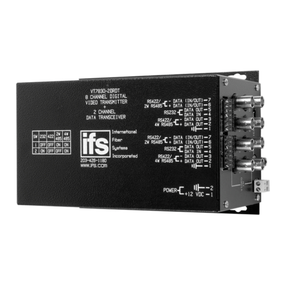
- Page 3 8 BNC Cables (Input from cameras) VT7830-2DRDT 8 CHANNEL DIGITAL VIDEO TRANSMITTER - DATA (IN/OUT) - 7 RS422/ 2 CHANNEL 2W RS485 DATA TRANSCEIVER + DATA (IN/OUT) - 6 DATA OUT - 5 RS232 DATA IN - 4 - DATA OUT - 3 RS422/ 4W RS485 + DATA OUT - 2...
- Page 4 VR7800-2DRDT TX RX TX RX VT VR VT VR VT VR VT VR CH 5 CH 6 CH 7 CH 8 VIDEO STATUS VT VR VT VR VT VR VT VR CH 1 CH 2 CH 3 CH 4 OPTICAL POWER CARRIER Optical data received...
- Page 5 VT7800-2DRDT TX RX TX RX OPTICAL CARRIER CH 7 CH 8 CH 5 CH 6 VIDEO STATUS CH 3 CH 4 CH 1 CH 2 POWER Optical data received Status indicating Electrical data transmitted LEDs will change Optical carrier received from RED to GREEN Camera on with these conditions.
- Page 6 INSTALLATION INSTRUCTIONS FOR ADDITIONAL COMPONENTS REQ UIRED TO MEET EMISSION REQUIREMENTS ON THE VT78XX-2DRDT-R3 and VR78XX-2DRDT-R3 Series RACK MOUNT UNITS. GASKET INSTALL SUPPLIED CONDUCTIVE FOAM GASKET (IFS P/N MMRFGSKT 375X500 or CHOMERICS P/N 82-122-74021-09600) CUT TO 4 INCH LENGTH AND PLA CE ON TOP RAIL OF THE RACK WHERE THE UNIT IS TO BE INSTALLED.
- Page 7 INSTALLATION INSTRUCTIONS FOR ADDITIONAL COMPONENTS REQ UIRED TO MEET EMISSION REQUIREMENTS ON THE VR78XX-2DRDT Series STAND ALONE UNIT. INSTALL SUPPLIED EMI FILTER CLAMPS (IFS P/N FL28A0640-0A0 or STEWARD P/N 28A0640-0A0) ON EACH DATA CABLE AS SHOWN.
-
Page 8: Fcc Compliance
FCC Compliance This device complies with Part 15 of the FCC Rules. Operation is subject to the following two conditions: (1) This device may not cause harmful interference, and (2) this device must accept any interference received, including interference that may cause undesirable operation. Changes or modifications not expressly approved by International Fiber Systems, Inc. - Page 9 Note: Be ready at the equipment before calling. Online Another great resource for assistance with your Interlogix product is our online publication library. To access the library, go to our website at the following location: http://www.interlogix.com/transmission Many Interlogix documents are provided as PDFs (portable document format). To read these documents, you will...
- Page 10 Product Disassembly Instructions for WEEE Per European Directive 2002/95/EC Waste Electrical and Electronic Equipment Required Tools: One number 2 Phillips (crosstip) screwdriver. One number 2 flat screwdriver. For the enclosed box version: 1. Locate and remove box cover securement screws. Usually, but not limited to, at least 4 screws.
- Page 11 Copyright © 2011 UTC Fire & Security. All rights reserved. Trademarks and Interlogix and IFS names and logos are trademarks of patents UTC Fire & Security. Other trade names used in this document may be trademarks or registered trademarks of the manufacturers or vendors of the respective products.
Need help?
Do you have a question about the VT7820-2DRDT and is the answer not in the manual?
Questions and answers