Mitsubishi Electric MFZ-KJ25VE Installation Manual
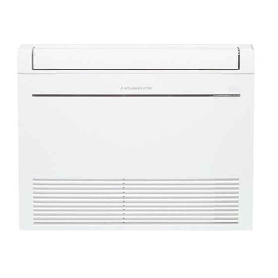
Floor type air conditioners
Hide thumbs
Also See for MFZ-KJ25VE:
- Service manual (40 pages) ,
- Operating instructions manual (13 pages) ,
- Installation manual (12 pages)
Advertisement
Quick Links
Advertisement

Related Manuals for Mitsubishi Electric MFZ-KJ25VE


Summary of Contents for Mitsubishi Electric MFZ-KJ25VE
- Page 1 FLOOR TYPE AIR CONDITIONERS MFZ-KJ25VE MFZ-KJ35VE MFZ-KJ50VE MFZ-KJ60VE For INSTALLER InstallatIon Manual English • When installing multi units, refer to the installation manual of the multi unit for outdoor unit installation. note: These models can be connected to the multi units, except for KJ60.
-
Page 2: Table Of Contents
Required tools for Installation ContEnts Phillips screwdriver Wrench (or spanner) Model names are indicated in 1-3. 1. BEFORE INSTALLATION ........1 Level 4 mm hexagonal wrench When installing multi units, refer to 2. INDOOR UNIT INSTALLATION ......3 Scale Flare tool for R410A the installation manual of the multi 3. OUTDOOR UNIT INSTALLATION .......6 Utility knife or scissors Gauge manifold for R410A unit for outdoor unit installation. 4. PURGING PROCEDURES, LEAK TEST, AND 25, 35 class 65 mm/ Vacuum pump for R410A TEST RUN ............7 50, 60 class 75 mm Charge hose for R410A 5. PUMPING DOWN ..........7 hole sawTorque wrench Pipe cutter with reamer 1. - Page 3 Power supply *1 Wire specifications *2 (thickness *3, *4) Pipe length and height difference Rated Breaker Power supply Indoor/outdoor Max. pipe length 20/30 m Indoor unit Outdoor unit Frequency Gas / Liquid Voltage capacity (3-core) connecting wire Max. height difference 12/15 m MFZ-KJ25VE MUFZ-KJ25VE ø9.52 / 6.35 mm 10 A 1.0 mm Max. number of bends *5, *6 MFZ-KJ35VE MUFZ-KJ35VE (0.8 mm) 4-core Refrigerant adjustment A *7 30/20 g/m 230 V 50 Hz MFZ-KJ50VE MUFZ-KJ50VE(HZ) 16 A 2.0 mm ø12.7 / 6.35 mm 2.0 mm...
-
Page 4: Indoor Unit Installation
2. InDooR unIt InstallatIon 2-1. FIXInG oF InDooR unIt MountInG BRaCKEt • Find a structural material (such as a stud) in the wall and fix bracket (7) horizontally with fixing screws (8). • To prevent bracket (7) from vibrating, be sure to install the fixing screws in the holes indicated in the illustration. For added support, fixing screws may also be installed in other holes. Wall 2-2. HolE DRIllInG ø65 mm (KJ25/35) 1) Determine the wall hole position. ø75 mm (KJ50/60) 5 - 7 mm 2) Drill a dia. 65 mm hole (dia. 75 mm for KJ50/60). The outdoor side should be 5 to 7 mm lower than the indoor side. Indoor Outdoor 3) Insert wall hole sleeve (C). side side HolE PosItIons FOR REAR OR LEFT-REAR PIPING FOR RIGHT DOWNWARD OR LEFT DOWN- FOR LEFT PIPING FOR RIGHT PIPING (The following figure is a front view WARD PIPING of the indoor unit installation location.) (The following figure is a view of the bottom of the indoor unit from above.) 2-3. - Page 5 2-4. INDOOR UNIT INSTALLATION 2-4-1. INSTALLING THE INDOOR UNIT ON THE FLOOR 1. Place the indoor unit on the flat floor. 2. Fix the indoor unit at 4 points with the included wood screws (9) and washers (10). Tighten the screws securely. 2-4-2. MOUNTING THE INDOOR UNIT ON THE WALL 1. Hook the top of the indoor unit on the indoor unit mounting bracket (7). 2. Fix the indoor unit at 4 points with the included wood screws (9) and washers (10). Tighten the screws securely. 2-4-3. EMBEDDING THE INDOOR UNIT IN A WALL 1. Make a hole in the wall. 2. Using reinforcement material, adjust the depth.
- Page 6 FOR LEFT OR LEFT-REAR PIPING Bundle the connecting pipes and drain hose together, and then wrap them in felt tape (11). Cut and use the lower side panels on the left and right sides of the indoor unit as Molding shown below. Smooth the cut edges of the side panels so that they will not damage the insulation Cut the lower side panels to coating. match the height of the molding. • For left or right piping • Installing flush against a wall with molding Start wrapping the piping tape (G) around the pipes and hose 10 mm inside the indoor unit. Wrap the felt tape (11) tightly around the pipes and hose starting near where the pipes and hose are routed from the indoor unit. (The overlap width of the felt Fasten the end of the felt tape (11) with a bandage stopper. tape (11) should not be more than 1/2 of the tape width.) Make sure that the drain hose Felt tape (11) is not routed upward. 2-7. DRaIn PIPInG • If the extension drain hose has to pass through a room, be sure to wrap it with commercially sold insulation.
-
Page 7: Outdoor Unit Installation
1) Remove the panel. 2) Open the cover of the indoor control P.C. board. 3) Join the connecting cable to CN105 and/or CN104 on the indoor control P.C. board. 4) Route the connecting cable through this point in the figure. 5) Attach the cable clamp provided with interface/connector cable to the thick part of the connecting cable with a screw 4×16 as shown in the figure. 6) Close the cover of the indoor control P.C. board. Be careful not to catch the thin part of the connecting cable in the cover. Reinstall the panel. WARNING 3) CN105 3) CN104 Fix the connecting cable at the prescribed position securely. When mounting the Incorrect installation may cause electric shock, fire, and/ or malfunction. interface and the connector cable, use this screw to fix the connecting cable. 3. outDooR unIt InstallatIon 3-1. ConnECtInG WIREs FoR outDooR unIt <KJ50, 60>... -
Page 8: Purging Procedures, Leak Test, And Test Run
4. PURGING PROCEDURES, LEAK TEST, AND TEST RUN 4-1. PURGING PROCEDURES AND LEAK TEST 1) Remove service port cap of stop valve on the side of the Compound pressure gauge – outdoor unit gas pipe. (The stop valves are fully closed and 0.101 MPa (for R410A) *4 to 5 turns Stop valve cap covered in caps in initial state.) – 760 mmHg) (Torque 19.6 to 2) Connect gauge manifold valve and vacuum pump to serv- Pressure gauge *Close 29.4 N•m, 200 (for R410A) Stop valve... - Page 12 HEAD OFFICE: TOKYO BLDG., 2-7-3, MARUNOUCHI, CHIYODA-KU, TOKYO 100-8310, JAPAN JG79A867H02...