
Related Manuals for Yamaha RST90G


Summary of Contents for Yamaha RST90G
- Page 1 OWNER’S MANUAL Read this manual carefully before operating this vehicle. RST90G RST90TFG RST90TFLG RST90TFYG LIT-12628-03-24 8JV-28199-70...
- Page 2 ESU10043 Les émissions du moteur de ce produit contiennent des substances chimiques connues dans l’État de Californie pour provoquer des cancers, des malformations congénitales et des troubles de la reproduction. Read this manual carefully before operating this vehicle. This manual should stay with this vehicle if it is sold.
- Page 3 Introduction ESU10122 RST90G RST90TFG Congratulations on your purchase of a RST90TFLG Yamaha snowmobile. This model is the result RST90TFYG of Yamaha’s vast experience in the produc- OWNER’S MANUAL tion of fine sporting and touring snowmo- ©2015 by Yamaha Motor Corporation, U.S.A.
- Page 4 Important manual information ESU10152 Particularly important information is distin- guished in this manual by the following nota- tions. This is the safety alert symbol. It is used to alert you to potential personal injury haz- ards. Obey all safety messages that follow this symbol to avoid possible injury or death.
-
Page 5: Table Of Contents
Contents Parking brake lever ....... 26 Location of the important labels..1 Shift lever ........26 Drive guard ........27 Safety information......6 V-belt holders ....... 28 Passenger grips (RST90TF / Description......... 8 RST90TFL / RST90TFY) .... 29 Passenger grip warmer switch ..29 Control functions...... - Page 6 Checking the throttle override LIMITED WARRANTY 2015 system (T.O.R.S.) ....... 66 and Later Models..... 114 Checking the air filter ....67 YAMAHA EXTENDED SERVICE Carburetors (RST90) ..... 70 (Y.E.S.) FOR U.S.A. High-altitude settings ....70 CUSTOMERS ......117 Valve clearance ......70 YAMAHA PROTECTION PLUS Engine oil and oil filter cartridge..
-
Page 7: Location Of The Important Labels
Read and understand all of the labels on your vehicle. They contain important information for safe and proper operation of your vehicle. Never remove any labels from your vehicle. If a label becomes difficult to read or comes off, a replacement label is available from your Yamaha dealer. - Page 8 Location of the important labels RST90 RST90TF / RST90TFL / RST90TFY...
- Page 9 Location of the important labels 1 RST90 ATTENTION 8ET-2815K-10 NOTICE 1 RST90TF / RST90TFL / RST90TFY WARNING AVERTISSEMENT 8ET-2815K-00 SEVERE INJURY OR DEATH MAY RESULT IF YOU IGNORE ANY OF AFIN D’ÉVITER TOUT RISQUE DE BLESSURE SÉRIEUSE OU MÊME MORTELLE, THE FOLLOWING: VEUILLEZ SUIVRE LES RECOMMANDATIONS SUIVANTES: •...
- Page 10 Location of the important labels WARNING AVERTISSEMENT • NEVER stand behind or near • Ne JAMAIS se tenir à proximité ou à a rotating track. l’arrière d’une chenille en mouvement. • Debris or a broken track could • Des débris ou une chenille cassée be thrown back with great force pourraient être projetés violemment et which could cause severe leg...
- Page 11 Location of the important labels 15 RST90TFL WARNING The unit contains nitrogen gas under high pressure. Do not incinerate, puncture, open, doing so may cause explosion and result in serious injury. See Owner’s manual. AVERTISSEMENT L’unité contient de I’azote sous haute pression. Ne pas lncinérer, perforer, ouvrir, car ceci pourrait causer une explosion et de graves blessures.
-
Page 12: Safety Information
Consult a Such use is prohibited by law, and you Yamaha dealer about any control or func- could collide with another vehicle. tion you do not understand. Be careful where you ride. There may be ... - Page 13 Genuine Yamaha Ac- cessories, which are available only from a Yamaha dealer, have been designed, tested, and approved by Yamaha for use on your snowmobile. Many companies with no con- nection to Yamaha manufacture parts and accessories or offer other modifications for Yamaha vehicles.
-
Page 14: Description
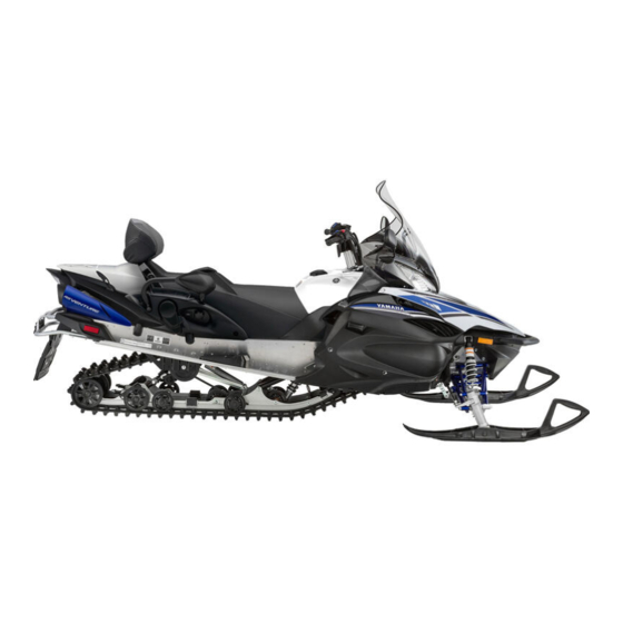
Description ESU10262 RST90 10,12 1,2,3,4 7 8 9 19 13 14 RST90TF / RST90TFL / RST90TFY 1,2,3 9 10,11,12 13 1. Battery 13. Tail/brake light 2. Main fuse 14. Tow hitch (RST90TF / RST90TFL / RST90TFY) / tow hitch bracket (RST90) 3. - Page 15 Description RST90 RST90TF / RST90TFL / RST90TFY 3 11 2 3 5 1. Brake lever 8. Main switch 2. Parking brake lever 9. Shift lever 3. Grip warmer adjusting switch 10. Auxiliary DC jack 4. Thumb warmer adjusting switch 11. Headlight beam switch 5.
-
Page 16: Control Functions
Control functions ESU13741 Main switch The main switch controls the ignition and lighting systems. The various positions are described below. 1. Starter (choke) lever Refer to the “Starting the engine” section on page 45 for proper operation. 1. Off 2. On 3. -
Page 17: Throttle Override System (T.o.r.s.)
“84” displays (RST90TF / RST90TFL / RST90TFY) or flash- es (RST90) in the meter display. If this occurs, have a Yamaha dealer check the system as soon as possible. RST90TF / RST90TFL / RST90TFY 1. Throttle lever... - Page 18 Control functions a digital speedometer The grip warmer level is initially displayed for a tachometer 5 seconds, then the display switches to the an odometer fuel meter. two tripmeters a fuel reserve tripmeter To switch the speedometer, odometer, and ...
- Page 19 Control functions ton to switch the display between the various tripmeter and odometer modes in the follow- ing order: TRIP F → ODO → TRIP A → TRIP B → TRIP F To reset a tripmeter, select it by pushing the “SELECT”...
- Page 20 Control functions been reached), the tripmeter must be reset Push the “RESET” button to change the after the oil change for the next periodic oil minute setting, and then push the “SE- change to be indicated at the correct time. LECT”...
- Page 21 Control functions Push and hold down the “SELECT” but- 1 2 3 4 ton. Turn the key to the on position, and then, after 5 seconds, release the “SELECT” button. Push the “RESET” button to select the desired display brightness level, and then push the “SELECT”...
-
Page 22: D-Mode (Drive Mode) (Rst90Tf / Rst90Tfl / Rst90Tfy)
Control functions Tripmeter shows the distance traveled since it last reset. Pushing the select/reset button switches the display between the odometer mode “ODO” and the tripmeter mode “TRIP” in the follow- ing order: ODO → TRIP → ODO To reset the tripmeter, push the select/reset button for at least 1 second while the tripme- ter is displayed. -
Page 23: Low Coolant Temperature Indicator Light
Control functions RST90 RST90 1. High beam indicator light “ ” 1. Low coolant temperature indicator light “ ” ESU13762 2. Warning light “ ” Low coolant temperature indi- 3. Engine trouble warning indicator “ ” cator light “ ” 4. - Page 24 Control functions RST90TF / RST90TFL / RST90TFY RST90TF / RST90TFL / RST90TFY 1. Fuel meter and grip/thumb warmer level in- 1. Fuel level warning indicator “ ” dicator 2. Warning light “ ” RST90 RST90 1. Fuel meter and grip/thumb warmer level in- 1.
- Page 25 Control functions When the thumb warmer adjusting switch is RST90TF / RST90TFL / RST90TFY pressed, the thumb warmer indicator comes on and the display switches to the thumb warmer level. See “Grip/thumb warmer adjusting switch” on page 23 for detailed information. RST90TF / RST90TFL / RST90TFY 1.
-
Page 26: Fuel Level Warning Indicator
If this occurs, have a Yamaha dealer inspect the snowmobile as soon as possible. RST90TF / RST90TFL / RST90TFY 1. -
Page 27: Oil Level/Pressure Warning Indicator (Rst90Tf / Rst90Tfl / Rst90Tfy)
If the oil level warning indicator and the warn- If the warning indicator and the warning light ing light still remain on, have a Yamaha dealer still remain on, have a Yamaha dealer check check the snowmobile. the snowmobile. -
Page 28: Coolant Temperature Warning Indicator
(See page 76 for checking comes on after the engine is started, the EPS procedures.) system may not be working correctly. When this occurs, have a Yamaha dealer check the RST90TF / RST90TFL / RST90TFY EPS system. 1. Coolant temperature warning indicator “... -
Page 29: Engine Stop Switch
Control functions to operate the engine longer than neces- sary if there is an error code to avoid pos- sible engine damage. [ECS00821] RST90TF / RST90TFL / RST90TFY 1. Engine stop switch “ ” During the first few rides, practice using the stop switch so that you can react quickly in an emergency. -
Page 30: Auxiliary Dc Jack
Control functions RST90TF / RST90TFL / RST90TFY See “Fuel meter and grip/thumb warmer level indicator” on page 17 for detailed informa- tion. ESU10697 Auxiliary DC jack The auxiliary DC jack is located in the front panel and can be used for accessories. The auxiliary DC jack can only be used if the engine is running. -
Page 31: Helmet Shield Heater Jack (Rst90Tf / Rst90Tfl / Rst90Tfy)
Control functions After using the auxiliary DC jack, be sure to remove the accessory power plug from the jack and to close the auxiliary DC jack cap. ECS00123 NOTICE To avoid circuit overload and a possible fuse blowing, do not use accessories re- quiring more than the maximum rated capacity for the auxiliary DC jack. -
Page 32: Parking Brake Lever
Control functions 1. Brake lever ESU10594 Shift lever The shift lever is used to put the snowmobile When the brake lever is squeezed, the brake into forward or reverse. After coming to a light comes on. complete stop, pull the shift lever out, slide it to “FWD”... -
Page 33: Drive Guard
Control functions 1. Pull out. 1. Pull out. 2. Slide to “REV” (reverse). 2. Slide to “REV” (reverse). 3. Release. 3. Release. ECS00073 NOTICE RST90 Do not use the shift lever while the snow- mobile is moving, otherwise the drive train could be damaged. -
Page 34: V-Belt Holders
Control functions The drive guard is designed to protect the V- belt clutch and V-belt in case parts break or come loose. The drive guard is located behind the left side cover [RST90TF / RST90TFL / RST90TFY (see page 60 for information on how to ac- cess the drive guard)], or under the shroud [RST90 (see page 62 for information on how to access the drive guard)]. -
Page 35: Passenger Grips (Rst90Tf / Rst90Tfl / Rst90Tfy)
Control functions RST90TF / RST90TFL / RST90TFY 1. Passenger grip 1. V-belt holder 2. Passenger grip adjusting knob RST90 To change the passenger grip posi- tion Remove the passenger grip adjusting knob by turning it counterclockwise. Move the passenger grip to the desired position. -
Page 36: Passenger Footrests
Control functions RST90 1. Footrest 1. Passenger grip warmer switch 2. Screw 2. Off 3. “HI” (high) ECS00132 NOTICE 4. “LO” (low) Make sure that the screws are tightened RST90TF / RST90TFL / RST90TFY securely after changing the position of the footrests. -
Page 37: Storage Compartment (Rst90Tf / Rst90Tfl / Rst90Tfy)
Control functions RST90 When riding without a passenger, the back- rest can be moved to the forward-most posi- tion, and its angle can be adjusted to suit the operator’s preference as shown. 1. Backrest 2. Backrest adjusting knob RST90TF / RST90TFL / RST90TFY ESU14860 Storage compartment (RST90TF / RST90TFL /... -
Page 38: Storage Areas (Rst90)
Control functions 1. Storage compartment latch 1. Storage pouch 2. Storage compartment lid ECS00782 NOTICE Before starting the engine, make sure that the tool kit is securely fastened and that the storage pouch zipper is completely closed. ESU10824 Storage areas (RST90) This snowmobile is equipped with a storage compartment, rear storage area, and rear carrier. - Page 39 Control functions Rear storage area and rear carrier The rear storage area and the rear carrier are located at the rear of the snowmobile. The rear storage area can be used only when the passenger seat is removed. 1. Backrest 2.
- Page 40 Control functions Align the holes in the backrest bracket with the bolts on the carrier lock bracket, and then place the backrest on the carri- er lock bracket. 1. Hole 2. Rear carrier 3. Bolt 4. Carrier lock bracket 1. Hole Slide the rear carrier backward until it stops.
-
Page 41: Tow Hitch (Rst90Tf / Rst90Tfl / Rst90Tfy) And Tow Hitch Bracket (Rst90)
1. Tow hitch bracket ECS00242 NOTICE To prevent premature wear of the V-belt, A tow hitch is available at a Yamaha dealer. avoid traveling under 10 km/h (6 mi/h) when towing for long distances or long pe- Tow weight limit: riods of time. - Page 42 (RST90TF, RST90TFL, RST90TFY) 39.3 L (10.38 US gal, 8.65 Imp.gal) (RST90) Your Yamaha engine has been designed to use regular unleaded gasoline with a pump octane number [(R+M)/2] of 86 or higher, or a research octane number of 91 or higher.
-
Page 43: Suspension
If you are not familiar with suspension adjust- adjusting nut in direction (a). To decrease ments, have a Yamaha dealer make these the spring preload and thereby soften adjustments. the suspension, turn the adjusting nut in... - Page 44 Control functions the spring preload and thereby soften Spring preload setting*: the suspension, turn the adjusting nut in Minimum (soft): 161.0 mm (6.34 in) (RST90) direction (b). 160.0 mm (6.30 in) (RST90TF / RST90TFL / RST90TFY) Standard: 162.0 mm (6.38 in) (RST90) 163.0 mm (6.42 in) (RST90TF / RST90TFL / RST90TFY) Maximum (hard):...
- Page 45 Control functions ESU13095 Tightening torque: Adjusting the 2-up adjusting blocks Locknut: (RST90) 42 Nm (4.2 m·kgf, 30 ft·lbf) EWS00761 WARNING Rear torsion springs Make sure that the 2-up adjusting blocks EWS00751 are installed in the same position on both WARNING sides of the snowmobile, otherwise poor The left and right spring preloads must be handling and loss of stability may result.
- Page 46 Control functions 1. 2-up position (rider and passenger) 2. Solo rider position 3. Special tool 4. Lock pin Pull the lock pin and turn the special tools to change the block position. Release the lock pin. Remove the special tools from the 2-up adjusting block.
- Page 47 Control functions RST90 ESU13114 Adjusting the spring preload of the sliding frame extension (RST90TF / RST90TFL / RST90TFY) EWS00751 WARNING The left and right spring preloads must be adjusted to the same setting. Uneven set- tings can cause poor handling and loss of stability.
-
Page 48: Performance Damper (Rst90Tfl)
* Distance A changes 1.25 mm (0.05 in) Do not dispose of a damaged or worn with each full turn of the adjusting nut. out damper yourself. Take the damper to a Yamaha dealer for any service. ESU14980 Performance damper ECS01110 NOTICE... -
Page 49: Pre-Operation Checks
• Make sure the drive guard is installed securely. Drive guard • Check the drive guard mounts for damage. • Check operation. • If soft or spongy, have Yamaha dealer bleed hy- draulic system. • Check brake pads for wear. Brake •... - Page 50 • Check the deflection. • Adjust if necessary. Drive track • Check for wear and damage. • If necessary, have a Yamaha dealer replace track. • Check for wear and damage. Slide runners • If necessary, have Yamaha dealer replace slide runners.
-
Page 51: Operation
Turn the main switch to the start position the engine does not start or if it stops and release it when the engine starts. again, ask a Yamaha dealer to inspect the NOTICE: Release the switch immedi- snowmobile. ately after the engine starts. If the en- ... - Page 52 Operation 1. Start 1. Run position 2. Off position Warm up the engine until it runs smooth- Fully open the starter (choke) lever. Be sure the low coolant temperature in- dicator light has gone out before opera- tion. (See page detailed information about the indicator light.) RST90...
-
Page 53: Break-In
After 800 km (500 mi) of operation, the engine oil must be changed and the oil filter cartridge replaced. If any engine trouble should occur dur- ing the engine break-in period, immedi- ately have a Yamaha dealer check the snowmobile. ESU11334 1. Start Riding your snowmobile... - Page 54 Operation Pay particular attention to the safety informa- A broken track, track fittings, or debris tion on page 6. thrown by the track could be danger- Please read all warning and notice labels on ous to bystanders. [EWS00691] your snowmobile. Also, read the Snowmobil- Braking er’s Safety Handbook that is supplied with EWS00221...
- Page 55 Operation higher speeds or in tighter curves. Lean more as the turn gets sharper or is made at higher speeds. Improper riding techniques such as abrupt throttle changes, excessive braking, incor- rect body movements, or too much speed for the sharpness of the turn may cause the snowmobile to tip.
- Page 56 Operation Snow and ice are slippery, so be prepared for the possibility that your snowmobile could begin to slip sideways on the slope. If this happens, steer in the direction of the slide if there are no obstacles in your path. As you regain proper balance, gradually steer again in the direction you wish to travel.
-
Page 57: Maximizing Drive Track Life
Operation track, slide runners, and drive sprockets. Op- ESU11351 Maximizing drive track life eration of the snowmobile on the following surfaces should be avoided at all times: Recommendations Dirt Track tension Sand During initial break-in, the new drive track will ... -
Page 58: Driving
Operation around the already weakened area. To mini- RST90TF / RST90TFL / RST90TFY mize possible damage, consult your stud manufacturer for installation and stud pattern recommendations. Yamaha does not recommend track stud- ding. ESU11396 Driving EWS00301 WARNING Be sure to read the “SAFETY INFORMA- 1. -
Page 59: Stopping The Engine
Operation 1. Pull out. 1. Off 2. Slide to “REV” (reverse). Push down the engine stop switch to stop 3. Release. the engine in an emergency. The reverse buzzer beeps while the shift lever is in reverse. While squeezing the brake lever, release the parking brake by moving the parking brake lever to the right, and then release the brake lever. - Page 60 Operation If transporting the snowmobile in an open trailer or truck, put a tight fitting cover on the snowmobile. A cover specifically de- signed for your snowmobile is best. This will help keep foreign objects out of the cooling vents, and also help protect the snowmobile against damage from debris on the road.
-
Page 61: Periodic Maintenance And Adjustment
Failure to properly maintain the snowmobile or performing maintenance activities incor- rectly may increase your risk of injury or death during service or while using the snow- mobile. If you are not familiar with snowmobile service, have a Yamaha dealer perform service. -
Page 62: Periodic Maintenance Chart For The Emission Control System
Periodic maintenance and adjustment ESU11462 Periodic maintenance chart for the emission control system Items marked with an asterisk should be performed by a Yamaha dealer as they require spe- cial tools, data and technical skills. INITIAL EVERY Seasonally 1 month... -
Page 63: General Maintenance And Lubrication Chart
Periodic maintenance and adjustment ESU11566 General maintenance and lubrication chart INITIAL EVERY Seasonally 1 month ITEM REMARKS PAGE or 800 km 4000 km (500 mi) (2500 mi) (40 hr) (200 hr) • Change (warm engine before Engine oil draining). Every Engine oil filter car- •... - Page 64 Periodic maintenance and adjustment INITIAL EVERY Seasonally 1 month ITEM REMARKS PAGE or 800 km 4000 km (500 mi) (2500 mi) (40 hr) (200 hr) Extrovert drive sprocket • Check for wear and damage. (RST90TF / • Replace if necessary. RST90TFL / RST90TFY) •...
-
Page 65: Tool Kit
If you do not have a torque wrench available during a service operation requiring one, take If you do not have a torque wrench available your snowmobile to a Yamaha dealer to during a service operation requiring one, take check the torque settings and adjust them if your snowmobile to a Yamaha dealer to necessary. -
Page 66: Recommended Equipment
Periodic maintenance and adjustment Shroud To remove the shroud Loosen the fasteners, slowly raise the shroud, and then unhook the shroud from the shroud stay. 1. Hexagon wrench cover 2. Hexagon wrench 3. Tool kit 4. Strap ESU14231 Recommended equipment 1. - Page 67 Periodic maintenance and adjustment Top cover To remove the top cover Remove the shroud and the left side cov- er. (See the above procedures.) Disconnect the auxiliary DC jack coupler. 1. Fastener 2. Left side cover To install a side cover Fit the projection on the rear of the side cover into the hole in the fuel tank cover.
-
Page 68: Opening And Closing The Shroud And Removing And Installing The Right Side Cover (Rst90)
Periodic maintenance and adjustment 1. Windshield stay rubber cover Tighten the quick fastener screws. Loosen the quick fastener screws. Place the windshield stay rubber covers Lift up the rear of the top cover, discon- in their original position. nect the main switch coupler, and then Pass the brake hose, throttle cable, park- remove the cover. -
Page 69: Checking The Spark Plugs
Do not attempt to diagnose such problems yourself. Instead, take the snowmobile to a Yamaha dealer for inspection and possible repairs. You should periodically remove and inspect the spark plugs because heat and deposits 1. -
Page 70: Adjusting The Engine Idling Speed (Rst90)
Periodic maintenance and adjustment Specified spark plug: Spark plug gap: Manufacturer: 0.7–0.8 mm (0.028–0.031 in) Model: When installing the spark plug, always clean CR8E the gasket surface. Wipe off any grime from the threads and tighten the spark plug to the EWS00711 specified torque. -
Page 71: Adjusting The Throttle Lever Free Play
Periodic maintenance and adjustment Remove the shroud and the top cover. Standard engine idling speed: (See page 60 for removal procedures.) 1300–1500 r/min Remove the headlight unit bolt and the Close the shroud. windshield stay bolts on each side of the snowmobile. -
Page 72: Checking The Throttle Override System (T.o.r.s.)
Periodic maintenance and adjustment 1. Locknut 1. Weatherstrip 2. Throttle lever free play adjusting bolt 10. Install the headlight unit bolts and wind- 3. Throttle lever free play shield stay bolts, and then tighten them to their specified torques. Throttle lever free play: 2.0–3.0 mm (0.08–0.12 in) Tightening torques: Headlight unit bolt:... -
Page 73: Checking The Air Filter
Yamaha dealer. Operating the snowmobile with a mal- functioning T.O.R.S. could result in loss of control. - Page 74 Periodic maintenance and adjustment RST90 Place the snowmobile on a level surface and apply the parking brake. Open the shroud. Remove the air filter case cover by un- hooking the case fastener and the case cover fasteners. Place the air filter element frame in the original position.
- Page 75 Periodic maintenance and adjustment 1. Headlight unit Place the air filter element frame in the Remove the air filter case cover by un- original position, and then install the air hooking the fasteners. filter case cover by hooking the fasten- ers.
-
Page 76: Carburetors (Rst90)
ESU11912 the area where you bought it, be sure to con- Carburetors (RST90) sult a Yamaha dealer. The dealer can tell you The carburetors are an important part of the if there are any changes necessary for the al- engine and its emission control system, titude where you plan to ride. -
Page 77: Engine Oil And Oil Filter Cartridge
Periodic maintenance and adjustment Start the engine, warm it up for 10–15 ESU13799 Engine oil and oil filter cartridge minutes, and then turn it off. The engine oil level should be checked before each use. In addition, the oil must be ... - Page 78 Periodic maintenance and adjustment RST90 RST90TF / RST90TFL / RST90TFY 1. Oil level gauge coupler 1. “H” level mark 2. Oil filler cap 2. “L” level mark Remove the oil filler cap, wipe the dip- RST90 stick clean, insert it back into the oil filler hole (without screwing it in), and then re- move it again to check the oil level.
- Page 79 Periodic maintenance and adjustment To change the engine oil (with or with- out oil filter cartridge replacement) Place the snowmobile on a level surface and apply the parking brake. Start the engine, warm it up for several minutes, and then turn it off. Remove the shroud, the right side cover, cover [RST90TF /...
- Page 80 Periodic maintenance and adjustment Remove the oil filler cap and the cylinder RST90 head cap, and then remove the engine oil drain bolt and its gasket to drain the oil from the oil tank. RST90TF / RST90TFL / RST90TFY 1. Engine oil drain bolt (oil tank) 2.
- Page 81 1. Oil filter cartridge Recommended engine oil: See page 110. An oil filter wrench is available at a Yamaha 16. Start the engine, warm it up for several dealer. minutes, and then turn it off.
-
Page 82: Cooling System
Periodic maintenance and adjustment RST90 and have a Yamaha dealer check the snowmobile. Continuing to operate the engine under such conditions could cause severe engine damage. [ECS00472] 21. Place the bottom panel in the original po- sition, and then install the bolts. - Page 83 If water has been added to the cool- ant, have a Yamaha dealer check the antifreeze content of the coolant as soon as possible, otherwise the effec- tiveness of the coolant will be re- 1.
- Page 84 The cooling system must be bled if the cool- ant reservoir becomes empty, if air can be seen in the coolant reservoir, or if there is a cooling system leak. Consult a Yamaha deal- ECS00501 NOTICE Operating the engine with an improperly bled cooling system can cause overheat- ing and severe engine damage.
-
Page 85: V-Belt
Check for any coolant leakage. If coolant is leaking, check for the cause. If you find any leaks, consult a Yamaha deal- Fill the coolant reservoir with coolant un- til it reaches the “COLD LEVEL” mark. Install the coolant reservoir cap. - Page 86 Periodic maintenance and adjustment Remove the shroud and the left side cov- er (RST90TF / RST90TFL / RST90TFY), or open the shroud (RST90), and then re- move the drive guard. (See page 27 for drive guard removal procedures.) Remove the screws and the bolts, and then pull the left lower cover outward to remove (RST90TF /...
- Page 87 Periodic maintenance and adjustment Tighten the V-belt position adjusting Standard V-belt position: bolts. From 1.5 mm (0.06 in) above the edge of the secondary sheave as- V-belt position adjusting bolt tightening sembly to 0.5 mm (0.02 in) below the torque: edge 10 Nm (1.0 m·kgf, 7.2 ft·lbf) If the V-belt position is incorrect, adjust it...
-
Page 88: Drive Chain Housing
Periodic maintenance and adjustment RST90TF / RST90TFL / RST90TFY RST90 1. Left lower cover 1. Dipstick 14. Install the drive guard, and then install Remove the dipstick and check that the the left side cover and the shroud, or oil is between the maximum and mini- close the shroud. -
Page 89: Brake And Parking Brake
1. Notch 2. Projection You could lose braking ability, which could lead to an accident. Ask a Yamaha Install the right side cover and the dealer to inspect and repair the brake shroud, or close the shroud. - Page 90 62 for the procedures)]. Check the brake pads for wear. If the brake pads reach the wear limit, ask a Yamaha dealer to replace them. 1. Parking brake pad wear limit Parking brake pad wear limit: 1.2 mm (0.047 in) Install the right side cover and the shroud, or close the shroud.
- Page 91 Periodic maintenance and adjustment Tighten the parking brake pad adjusting bolt locknut. Install the right side cover and the shroud, or close the shroud. Checking the brake fluid level Before riding, check that the brake fluid is above the lower level. Check the brake fluid level with the top of the reservoir level.
-
Page 92: Extrovert Drive Sprocket (Rst90Tf / Rst90Tfl / Rst90Tfy)
2. Measuring line the brake system for leakage. If the brake flu- 3. Drive sprocket tooth width id level goes down suddenly, have a Yamaha ESU14661 dealer check the cause before further riding. Skis and ski runners... -
Page 93: Steering System
Turn the handlebar so the skis face straight ahead. Check the following for ski alignment: Skis are facing forward. If excessive free play is felt, consult a Yamaha Ski toe-out (distance A – distance B) is dealer. within specification. - Page 94 Periodic maintenance and adjustment 1. Handlebar cover Loosen the handlebar bolts. 1. Area where projection cannot be installed Tighten the front handlebar bolts to the 1. Handlebar bolt specified torque, and then tighten the rear handlebar bolts to the specified Move the handlebar up or down to adjust torque.
-
Page 95: Drive Track And Slide Runners
Periodic maintenance and adjustment Adjust or replace if necessary. (See the fol- ESU12179 Drive track and slide runners lowing section for more details.) Drive track EWS00482 WARNING A broken track, track fittings or debris thrown by the drive track could be danger- ous to an operator or bystanders. - Page 96 Periodic maintenance and adjustment 1. Spring scale 1. Rear axle nut Lift the rear of the snowmobile onto a suitable stand to raise the drive track off Measure the gap between the slide runner the ground. and the edge of the track window on both Start the engine and rotate the drive sides.
- Page 97 Periodic maintenance and adjustment Shifted to right Recheck alignment and deflection. If necessary, repeat steps 3 to 5 until the proper adjustment is achieved. Lower the snowmobile to the ground. Tighten the rear axle nut. Rear axle nut tightening torque: 75 Nm (7.5 m·kgf, 54 ft·lbf) Slide runners Check the slide runners for wear and dam-...
-
Page 98: Lubrication
Periodic maintenance and adjustment ECS00351 NOTICE Ride on fresh snow frequently. Operating on ice or hard-packed snow will rapidly wear the slide runners. ESU12199 Lubrication Lubricate the following points with the speci- fied grease. EWS00512 1. Throttle cable end WARNING Do not grease the throttle cable because it could become frozen, which could cause loss of control. -
Page 99: Replacing A Headlight Bulb
Periodic maintenance and adjustment RST90 Unhook the bulb holder, and then re- move the burnt-out bulb. 1. Grease nipple 1. Bulb holder RST90TF / RST90TFL / RST90TFY Install a new bulb, and then hook the bulb holder onto the headlight unit. NOTICE: Keep oil and your hands away from the glass part of the bulb or its life and illumination will be affect-... - Page 100 Periodic maintenance and adjustment Remove the headlight unit bolt and the windshield stay bolts on each side of the snowmobile. 1. Headlight coupler 2. Bulb holder cover Unhook the bulb holder, and then re- 1. Headlight unit bolt move the burnt-out bulb. 2.
-
Page 101: Adjusting The Headlight Beams
Periodic maintenance and adjustment 1. Do not touch the glass part of the bulb. 1. Weatherstrip 11. Install the headlight unit bolts and wind- Bulb type: shield stay bolts, and then tighten them Halogen bulb to their specified torques. Install the bulb holder cover, and then Tightening torques: connect the headlight coupler. -
Page 102: Fittings And Fasteners
Periodic maintenance and adjustment 1. Headlight beam adjusting screw 1. Phillips screwdriver Install the top cover. Close the shroud. ESU12291 RST90 Fittings and fasteners Open the shroud. Check the tightness of the fittings and fasten- Insert a Phillips screwdriver into the hole ers. -
Page 103: Replacing A Fuse
KEEP OUT OF THE REACH OF CHILDREN. age or A FIRE HAZARD. Charge or have a Yamaha dealer charge the ECS00632 battery as soon as possible if it seems to NOTICE have discharged. - Page 104 Periodic maintenance and adjustment Be careful not to scratch the snowmo- Slide the oil tank breather hose clamp bile when moving the headlight unit. away from the air filter case, and then disconnect the oil tank breather hose. [ECS00921] 1. Headlight unit 1.
- Page 105 Periodic maintenance and adjustment Disconnect the negative battery lead by removing the bolt. 1. Negative battery lead 2. Bolt 10. Replace the blown fuse with one of the proper amperage. 1. “IGN” (ignition) fuse 2. “ETV” (electronic throttle valve) fuse 3.
- Page 106 14. Install the headlight unit, making sure to If the fuse immediately blows again, ask a fit the slots on its bottom onto the projec- Yamaha dealer to inspect the snowmobile. tions on its stay. RST90 The main fuse is located under the air filter case.
- Page 107 Periodic maintenance and adjustment 1. Air filter case fastener 1. Crankcase breather hose clamp (crankcase side) Loosen the joint clamp bolts. 2. Crankcase breather hose Lift up the air filter case, slide the crank- case breather hose clamp (air filter case side) down, disconnect the crankcase breather hose from the air filter case, and then remove the air filter case.
- Page 108 12. Install the right side cover and close the shroud. If the fuse immediately blows again, ask a Yamaha dealer to inspect the snowmobile. 1. Fuse box 2. “HEAD” (headlight) fuse 3. “SIG” (signaling system) fuse 4.
-
Page 109: Troubleshooting
• Clogged fuel line: Clean fuel line. ↓ • Clogged injector (RST90TF / RST90TFL / RST90TFY): Ask a Yamaha dealer to check. • Clogged carburetor (RST90): Clean carburetor. Fuel supplied to combustion chamber • Flooded engine (RST90TF / RST90TFL / RST90TFY): Crank engine or wipe spark plugs dry. - Page 110 Apply the parking brake and turn the key • Worn or damaged piston and cylin- to the off position. der: Remove the shroud and the right side Ask a Yamaha dealer to check. cover [RST90TF / RST90TFL / RST90TFY (see page 60 for the proce-...
- Page 111 (–) connecting operates slowly lead. Engine stop switch is pushed in: Pull it out. Faulty wire connections: Check connec- tions or ask a Yamaha dealer to check. Discharged battery: Charge battery or see “Discharged battery” above.
- Page 112 Remove spark plugs and Yamaha dealer to check. turn engine over several times with ignition V-belt twists off to expel excess fuel. Ask a Yamaha Improper V-belt: Replace with correct V- dealer to check. belt. Incorrect V-belt clutch offset: Ask a Engine power is low ...
- Page 113 Troubleshooting Worn or damaged drive track: Ask a Yamaha dealer to check.
-
Page 114: Storage
In areas where oxygenated fuel (gasohol) is used, complete- steam-jet cleaners since they cause wa- ly drain the fuel system. Consult a Yamaha ter seepage and deterioration in the fol- dealer if further information is needed. - Page 115 Yamaha dealer. The dealer has tic, and rubber parts. the experience and training to help you get...
-
Page 116: Specifications
Specifications Fuel: ESU1246H Recommended fuel: REGULAR UNLEADED GASOLINE ONLY Dimensions: Minimum pump octane (R+M)/2: Overall length: 3215 mm (126.6 in) Starting system: Overall width: Electric starter 1202 mm (47.3 in) Chassis: Overall height: Drive track: 1330 mm (52.4 in) (RST90) Material: 1380 mm (54.3 in) (RST90TF, RST90TFL, Molded rubber, fiberglass-rod reinforced... - Page 117 Specifications Shift speed [Subject to change according to Electrical system: elevation settings. Usually achieved after Ignition system: approximately 800 m (0.5 mi) traveled.]: 8000–8750 r/min (RST90TF, RST90TFL) Spark plug: 8250–8750 r/min (RST90) Manufacturer: Drive chain type: Silent chain enclosed in oil bath Model: Drive chain housing oil: CR8E...
-
Page 118: Consumer Information
Record the frame serial number, engine serial number (Primary ID), and key identification number in the spaces provided for assistance when ordering spare parts from a Yamaha dealer. Also, record and keep the ID numbers in a separate place in case the snowmobile is sto- len. -
Page 119: Vehicle Emission Control Information Label
Consumer information ESU13462 Vehicle Emission Control Infor- mation label RST90 1. Vehicle Emission Control Information label RST90TF / RST90TFL / RST90TFY 1. Vehicle Emission Control Information label The Vehicle Emission Control Information la- bel is affixed at the location in the illustration. This label shows specifications related to ex- haust emissions as required by federal law, state law and Environment Canada. -
Page 120: Yamaha Snowmobile Limited Warranty 2015 And Later Models
Yamaha snowmobile dealer, shall, free of Failures other than those resulting from defects in charge, repair or replace, at Yamaha’s option, any part material or workmanship which arise solely as a result adjudged... - Page 121 Q. Will the warranty be void or canceled if I do not operate or maintain my new Yamaha exactly as specified in the Owner’s Manual? A. No. The warranty on a new Yamaha cannot be “voided” or “canceled.” However, if a particular failure is caused by operation or maintenance other than as shown in the Owner’s Manual, that failure...
- Page 122 Consumer information Q. What responsibility does my dealer have under this When contacting Yamaha, be sure to include the model, warranty? serial number, names, dates, and receipts. A. Each Yamaha snowmobile dealer is expected to: 1. Completely set up every new machine before sale.
-
Page 123: Yamaha Extended Service (Y.e.s.) For U.s.a. Customers
Consumer information ESU12514 YAMAHA EXTENDED SERVICE (Y.E.S.) FOR U.S.A. CUSTOMERS... -
Page 124: Yamaha Protection Plus (Ypp) For Canadian Customers
• Under the Yamaha Protection Plus program, Yamaha picks up the entire cost of parts and labour to repair every applicable mechanical defect. • Yamaha’s computerized warranty system is updated... -
Page 125: Index
Index Helmet shield heater jack (RST90TF / Air filter, checking ........67 RST90TFL / RST90TFY) ....... 25 Auxiliary DC jack ........24 High beam indicator light ......16 High-altitude settings ....... 70 Backrest ........... 30 Battery............96 Identification numbers ......112 Brake and parking brake...... - Page 126 Index Sliding frame extension, adjusting spring preload........41 Spark plugs, checking ......63 Specifications......... 110 Starter (choke) lever (RST90) ....10 Starting the engine........45 Steering system ........87 Stopping the engine......... 53 Storage ..........108 Storage areas (RST90) ......32 Storage compartment ......
- Page 127 Genuine Yamaha Accessories – Yamaha only offers accessories that meet our high standards for quality and performance. Buy with confidence, knowing your Genuine Yamaha Accessories will fit right and perform right – right out of the box. Yamalube – Take care of your Yamaha with legendary Yamalube oils, lubricants, and care products.
- Page 128 Printed in Japan Printed on recycled paper 2015.04-0.5×1 CR...