
Summary of Contents for Honeywell Home LTEM-PV
- Page 1 LTEM-PV LTEM-PA Internet and Cellular Communicator Installation and Setup Guide R800-26394A 10/20 Rev A...
-
Page 3: Table Of Contents
Table of Contents SECTION 1: General Information ..................................1 System Overview ....................................1 Introduction ....................................1 General Information ................................. 1 System Features ....................................2 About AlarmNet Internet Application ............................3 Supervision Features ..................................3 Remote Services ....................................3 Control Panel Connections ................................4 ECP Connection .................................. - Page 4 LTEM-P Installation and Setup Guide Appendices ........................................... 27 Appendix A: Summary of LED Operation ..........................27 Appendix B: ......................................28 Appendix C: Glossary ..................................29 Regulatory Notes ..................................... 30 Summary of Connections Diagram Inside Back Cover...
-
Page 5: Section 1: General Information
AlarmNet for subsequent transfer to the central monitoring station. The LTEM-P Series includes the following models: • LTEM-PV (Verizon network) • LTEM-PA (AT&T network) The communicator also supports the following optional plug-in modules: •... -
Page 6: System Features
LTEM-P Installation and Setup Guide System Features Basic features of the communicator include: • Quick connection to Resideo control panels and compatible non-Resideo control panels • Supports both ECP and Bus connections to compatible control panels • Power supplied by a 9VDC Power Adapter (included) •... -
Page 7: About Alarmnet Internet Application
Section 1: General Information About AlarmNet Internet Application AlarmNet is a fully encrypted, secure method of delivering alarm messages from a protected premise to an AlarmNet equipped central station. An Internet Communicator transmits status, supervisory, and alarm messages to the AlarmNet Control Center using a broadband Internet connection. The AlarmNet Control Center identifies, validates, and forwards the messages to the appropriate AlarmNet central station. -
Page 8: Control Panel Connections
LTEM-P Installation and Setup Guide Control Panel Connections The communicator provides two types of control panel connections so it can be used with various types of control panels, as summarized below. ECP Connection • This connection is for Resideo VISTA control panels that support ECP communication Total Connect 2 Compatibility Note: The following VISTA control panel firmware versions support Total Connect 2 Communication (version number is located on the panel's PCB PROM label): Control Panel... -
Page 9: Specifications
UL installations: 0% to 85%; for ULC installations 0% to 93% Altitude: to 10,000 ft. operating, to 40,000 ft. storage Frequency Bands Band 2 Band 4 Band 5 Band 12 Band 13 LTEM-PV LTEM-PA Output Power Class 5 20dBm (conducted) -
Page 10: Compatibility
LTEM-P Installation and Setup Guide Compatibility Control Panels: For a list of control panels that are compatible with various features of this device, go to: https://mywebtech.honeywellhome.com/ Compass Version: Compatible with Compass Version v2.2.35.1 (or higher) for VISTA series control panel IP/Cellular Downloading Compliance This device has been tested by ETL to meet the following standards: UL1610 Central-Station Burglar-Alarm Units... -
Page 11: Section 2: Mounting And Wiring
Mounting and Wiring Installation Notes • The communicator must be installed in accordance with the National Electrical Code, ANSI/NFPA 70. • The communicator must be mounted indoors within the protected premises. • Do not install in air-handling spaces. • Do not mount the communicator on or near metal objects, as this may affect radio communication. -
Page 12: Mounting The Communicator
LTEM-P Installation and Setup Guide Mounting the Communicator There are two mounting options: • Mount the Communicator directly to a wall, secured with six screws and a wall tamper screw • Mount the Communicator to a VISTA control panel cabinet, secured to the cabinet via a threaded bushing and locking nut. -
Page 13: Mounting The Module On A Vista Control Panel Cabinet
Section 2: Mounting and Wiring Mounting the Communicator on a VISTA Control Panel Cabinet 1. Ensure power to the control panel (both AC and battery) is off, then remove the knockout on the top left of the control panel cabinet. 2. -
Page 14: Wiring The Communicator
LTEM-P Installation and Setup Guide Wiring the Communicator Wiring for VISTA Series ECP Control Panels Most Resideo VISTA control panels support ECP data communication, (e.g., VISTA-15P, VISTA-20P, VISTA-128BPT and VISTA-128FBPT). However, there are some panels that do not. Check the Installation and Setup Guide for the control panel you are using to see if it supports ECP communication. -
Page 15: Wiring For Bus Connection Control Panels
Section 2: Mounting and Wiring ECP & BUS Connection Maximum Wire Lengths Minimum Distance from Wire Gauge Control Panel 75 ft (23m) 120 ft (37m) 170 ft (52m) 270 ft (82m) Wiring for Bus Connection Control Panels For control panels that do not support ECP data communication, use the communicator's bus terminals to connect the communicator to the control panel' data terminals. - Page 16 LTEM-P Installation and Setup Guide DSC Control Panel Connections This section applies to the following DSC PowerSeries (PC) control panels: • PC1616 • PC1832 • PC1864 1. Connect the control panel terminals labeled Black (BLK), Yellow (YEL), and Green (GRN) to the communicator's GND, TX, and RX terminals respectively.
-
Page 17: Wiring The Fault Trigger Output
Section 2: Mounting and Wiring Wiring the Fault Trigger Output The communicator's fault trigger output (Trigger Output terminal T1) can be wired and programmed for fail-safe mode (see the program option "FAULT RELAY NORMALLY ON"). To sense a communicator fault at the control panel, see the diagram below. 1. -
Page 18: Power Connections
LTEM-P Installation and Setup Guide Power Connections Connecting the Power Adapter The communicator is powered from the supplied plug-in Power Adapter. 1. Connect the Power Adapter to the communicator's PWR and GND terminals as shown below. Observe polarity. 2. Power Up: After all wiring connections have been made and all optional plug-in modules have been installed, plug the Power Adapter into a 24-hour, non-switched 110 - 240VAC outlet. -
Page 19: Installing Optional Plug-In Modules
Section 2: Mounting and Wiring Installing Optional Plug-in Modules LTE Communication Module If enhanced cell radio features are desired, install the optional PROLTE Series Communication plug- in module. Models include PROLTE-V and PROLTE-A. Refer to the instructions included with the PROLTE Series module for additional information. - Page 20 LTEM-P Installation and Setup Guide 2. Install the PROWIFIZW module by mating the module's connector to edge connector on the upper left side of the communicator's PCB. Make sure the module is fully seated in the connector. Slip the module board under the clip tab to lock it in place as shown below. 3.
-
Page 21: Dialer Capture Module
Section 2: Mounting and Wiring Dialer Capture Module An optional Dialer Capture module (PRODCM)can be used for controls that send Contact ID alarm signals via the control panel's dialer. The dialer capture module replaces the phone line and simulates the phone service to the control panel. The alarms are then sent to AlarmNet for routing to the central monitoring station. - Page 22 LTEM-P Installation and Setup Guide Additional Notes When Using the Dialer Capture Module • The Dialer Capture module supports only one-way communications (from the control panel to the central station). For those control panels that support two-way voice communications, speakerphone, paging, follow-me, etc., these features will no longer be available. The control panel must be programmed for one-way communications only.
-
Page 23: External Antenna
Section 2: Mounting and Wiring External Antenna If adequate signal strength cannot be achieved with the internal antenna, an external antenna can be used. An Antenna Kit with an antenna cable, adapter cable, clamp, and bracket will be required. Instructions for mounting the antenna are provided with the kit. The following Antenna Kits are compatible: CELL-ANTHB •... - Page 24 LTEM-P Installation and Setup Guide...
-
Page 25: Section 3: Programming The Communicator
City ID = 01-99; Central Station ID = 01-FE (HEX); Subscriber ID = 0001-9999 Device Type displays the model number for the communicator being Device Type programmed. • LTEM-PA • LTEM-PV Panel Type indicates the type of control panel to which the communicator is Panel Type connected. • VISTA •... - Page 26 LTEM-P Installation and Setup Guide Supervision time is factory-set to "Daily" (24 hours) and cannot be changed. Supervision • Daily The AlarmNet network must hear at least one supervisory message from the communicator during this supervision period; otherwise, AlarmNet notifies the central station that a communication failure has occurred.
- Page 27 Section 3: Programming the Communicator The Fault Relay Normally On option enables fail-safe mode, which causes the Fault Relay Normally On fault trigger open collector output to be normally energized to ground and de- (Fail-Safe Mode) energizes (open circuit) upon a communicator fault condition (if respective alarm •...
-
Page 28: Ecp Status Codes
LTEM-P Installation and Setup Guide NOTE: In order to select email notification (Multi Mode), an account must be created in AlarmNet 360 and “Remote Access” must be selected. Multi-Mode (email notification) is intended as a convenience for the user and does not replace Central Station reporting of critical events (alarms, troubles, etc.). -
Page 29: Section 4: Registration
Registration Registering the Communicator Once you have programmed the communicator, it must be registered. Registering the communicator activates the account with AlarmNet and enables the security system's control panel to send reports. Before the communicator is registered, the REG (green) LED will be on. You can monitor the registration process by viewing the display LEDs. - Page 30 LTEM-P Installation and Setup Guide...
-
Page 31: Appendices
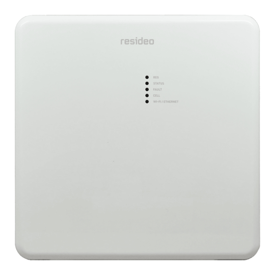
Appendices Appendix A: Summary of LED Operation LTEM-P Initial Power Up: Upon initial power up, the communicator LEDs blink in repeated sequence from top to bottom indicating network initialization. Green (REG) Yellow (STATUS) Red (FAULT) Green (CELL) Green (WIFI) LED INDICATIONS DESCRIPTION Module is NOT registered with AlarmNet... - Page 32 Appendix B: Central Station Contact ID Messages Alarm Condition Alarm Code Restore Code Power On / Reset E339 C08xx* Tamper E341 C08xx* R341 C08xx* (Compromise Indication) Power Loss E337 C08xx* R337 C08xx* Low Battery E338 C08xx* R338 C08xx* Battery Charger Failure E314 C08xx* R314 C08xx* ECP Supervision...
-
Page 33: Appendix C: Glossary
Appendix C: Glossary Refers to the fourth generation of cellular wireless standards. It is a successor to 3G 4G LTE and 2G families of standards. 4G provides up to 10 times the data transfer speeds of 3G. DACT Digital Automated Communications Terminal Dynamic Host Configuration Protocol, which provides a mechanism for allocating IP DHCP addresses dynamically so that addresses can be reused when hosts no longer need... -
Page 34: Regulatory Notes
TO THE INSTALLER LTEM-PV: The external antenna gain shall not exceed 6.94 dBi for 700 MHz, 6.00 dBi for 1700 MHz, and 9.01 dBi for 1900 MHz. Under no conditions may an antenna gain be used that would exceed the ERP and EIRP power limits as specified as specified in FCC Parts 22H, 24E and 27. - Page 35 Summary of Connections LED STATUS NOT registered with AlarmNet (green) Module is registered with AlarmNet FAST BLINK Download session with Compass in progress SLOW BLINK In unison with STATUS, registration in progress STATUS Periodic BLINK Normal (indicates Power On) (yellow) FAST BLINK Cannot deliver alarms Idle power abnormal...
- Page 36 P.O. Box 9040, Melville, NY 11747 www.resideo.com © 2020 Resideo Technologies, Inc. All rights reserved. The Honeywell Home trademark is used under license from Honeywell International, Inc. This product is manufactured by Resideo Technologies, Inc. and its affiliates. R800-26394A 10/20 Rev A...
Need help?
Do you have a question about the LTEM-PV and is the answer not in the manual?
Questions and answers