Table of Contents
Advertisement
Quick Links
TABLE OF CONTENTS
1 Safety Precautions----------------------------------------------- 3
2 Specifications ----------------------------------------------------- 5
2.1. CS-C12EKF CU-C12EKF ------------------------------- 5
3 Features ------------------------------------------------------------- 7
4 Location of Controls and Components ------------------- 8
4.1. Product Overview------------------------------------------ 8
5 Dimensions--------------------------------------------------------- 9
5.1. Indoor Unit & Remote Control -------------------------- 9
5.2. Outdoor Unit -----------------------------------------------10
6 Refrigeration Cycle Diagram --------------------------------11
7 Block Diagram----------------------------------------------------12
8 Wiring Connection Diagram ---------------------------------13
8.1. CS-C12EKF CU-C12EKF ------------------------------13
9 Printed Circuit Board-------------------------------------------14
9.1. Indoor Unit--------------------------------------------------14
9.2. Indicator-----------------------------------------------------16
10 Installation Instruction-----------------------------------------17
10.1. Select The Best Location -------------------------------17
CS-C12EKF CU-C12EKF
PAGE
10.2. Indoor Unit ------------------------------------------------- 18
10.3. Outdoor Unit----------------------------------------------- 20
11 Operation and Control ---------------------------------------- 23
11.1. Cooling Operation---------------------------------------- 23
11.2. Soft Dry Operation --------------------------------------- 24
11.3. Automatic Operation ------------------------------------ 25
11.4. Operation Control ---------------------------------------- 26
11.5. Indoor Fan Speed Control ----------------------------- 29
11.6. Outdoor Fan Speed Control --------------------------- 30
11.7. Vertical Airflow Direction Control --------------------- 31
11.8. Horizontal Airflow Direction Control ----------------- 31
11.9. Powerful Operation -------------------------------------- 31
11.10. Quiet Operation------------------------------------------- 32
11.11. Timer Control---------------------------------------------- 33
11.12. Random Auto Restart Control ------------------------ 33
11.13. Remote Control Signal Receiving Sound ---------- 33
12 Service Mode ----------------------------------------------------- 34
12.1. Auto OFF/ON Button ------------------------------------ 34
© 2006 Panasonic HA Air-Conditioning (M) Sdn Bhd
(11969-T). All rights reserved. Unauthorized copying
and distribution is a violation of law.
Order No. MAC0601005C3
Air Conditioner
PAGE
Advertisement
Table of Contents

Related Manuals for Panasonic CS-C12EKF


Summary of Contents for Panasonic CS-C12EKF
-
Page 1: Table Of Contents
10 Installation Instruction-----------------------------------------17 12 Service Mode ----------------------------------------------------- 34 10.1. Select The Best Location -------------------------------17 12.1. Auto OFF/ON Button ------------------------------------ 34 © 2006 Panasonic HA Air-Conditioning (M) Sdn Bhd (11969-T). All rights reserved. Unauthorized copying and distribution is a violation of law. - Page 2 12.2. Remote Control Button --------------------------------- 34 12.3. Test Mode Timer Table---------------------------------- 35 13 Troubleshooting Guide---------------------------------------- 36 13.1. Refrigeration cycle system----------------------------- 36 14 Disassembly and Assembly Instructions --------------- 38 14.1. Indoor Electronic Controllers Removal Procedures------------------------------------------------- 38 14.2. Indoor Fan Motor and Cross Flow Fan Removal Procedures ------------------------------------ 40 15 Technical Data---------------------------------------------------- 42 15.1.
-
Page 3: Safety Precautions
1 Safety Precautions • Read the following “SAFETY PRECAUTIONS” carefully before perform any servicing. • Electrical work must be installed or serviced by a licensed electrician. Be sure to use the correct rating of the power plug and main circuit for the model installed. •... - Page 4 ATTENTION 1. Selection of the installation location. Select an installation location which is rigid and strong enough to support or hold the unit, and select a location for easy maintenance. 2. Power supply connection to the conditioner. Connect the power supply cord of the air conditioner to the mains using one of the following methods.
-
Page 5: Specifications
2 Specifications 2.1. CS-C12EKF CU-C12EKF Unit Indoor unit Outdoor unit Power Source (Phase, Voltage, Cycle) ø, V, Hz Single, 220 - 240, 50 Cooling Capacity kW (BTU/h) 3.58 - 3.60 (12,200 - 12,300) Moisture Removal l/h (Pint/h) 2.1 (4.4) Airflow Method... - Page 6 Unit Indoor unit Outdoor unit Refrigerant (R-22) g (oz) — 870 (30.7) Thermostat — — Protection Device — 2 Stage Overload Protector Capillary Tube Length — Flow Rate I/min — 14.0 Inner Diameter — Air Filter Material P.P. — Style Honeycomb Capacity Control Capillary Tube...
-
Page 7: Features
3 Features • High Efficiency • Compact Design • Wider range of horizontal discharge air • Air Filter with function to reduce dust and smoke • Automatic air swing and manual adjusted by Remote Control for vertical airflow • Long Installation Piping - CS/CU-C12EKF, long piping up to 15 meter •... -
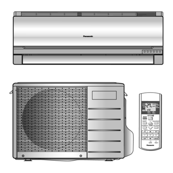
Page 8: Location Of Controls And Components
4 Location of Controls and Components 4.1. Product Overview 4.1.1. Indoor Unit 4.1.2. Outdoor Unit 4.1.3. Remote Control... -
Page 9: Dimensions
5 Dimensions 5.1. Indoor Unit & Remote Control 5.1.1. CS-C12EKF... -
Page 10: Outdoor Unit
5.2. Outdoor Unit 5.2.1. CU-C12EKF... -
Page 11: Refrigeration Cycle Diagram
6 Refrigeration Cycle Diagram... -
Page 12: Block Diagram
7 Block Diagram... -
Page 13: Wiring Connection Diagram
8 Wiring Connection Diagram 8.1. CS-C12EKF CU-C12EKF Resistance of Outdoor Fan Motor Windings Resistance of Compressor Windings MODEL CU-C12EKF MODEL CU-C12EKF CONNECTION CWA951120 CONNECTION 2KS210D3BA02 200.4 Ω 1.930 Ω BLUE-YELLOW C - R 252.5 Ω 2.449 Ω YELLOW-RED C - S Note: Resistance at 26°C of ambient temperature. -
Page 14: Printed Circuit Board
9 Printed Circuit Board 9.1. Indoor Unit TOP VIEW... - Page 15 BOTTOM VIEW...
-
Page 16: Indicator
9.2. Indicator TOP VIEW BOTTOM VIEW... -
Page 17: Installation Instruction
10 Installation Instruction 10.1. Select The Best Location Indoor Unit Indoor/Outdoor Unit Installation Diagram • There should not be any heat source or steam near the unit. • There should not be any obstacles blocking the air circula- tion. • A place where air circulation in the room is good. •... -
Page 18: Indoor Unit
10.2. Indoor Unit 10.2.2. To Drill A Hole In The Wall And Install A Sleeve Of Piping 10.2.1. How To Fix Installation Plate 1. Insert the piping sleeve to the hole. The mounting wall is strong and solid enough to prevent it from 2. - Page 19 For the embedded piping Insert the connecting cable Install the Indoor unit Secure the Indoor Unit Pull out the piping and drain hose (This can be used for left rear piping & left bottom piping also.) How to keep the cover...
-
Page 20: Outdoor Unit
• How to pull the piping and drain hose out, in case of the 10.3. Outdoor Unit embedded piping. 10.3.1. Install The Outdoor Unit • After selecting the best location, start installation according to Indoor/Outdoor Unit Installation Diagram. 1. Fix the unit on concrete or rigid frame firmly and horizon- tally by bolt nut (ø10 mm). - Page 21 Decide piping length and then cut by using pipe cutter. Remove burrs from cut edge. Make flare after inserting the flare nut (locate at valve) onto the copper pipe. Align center of piping to valves and then tighten with torque wrench to the specified torque as stated in the table.
- Page 22 4(A). Checking gas leakage for the left piping (1) * Connect the manifold gauge to the service port of 3-way valve. * Measure the pressure. (2) * Keep it for 5-10 minutes. * Ensure that the pressure indicated on the gauge is the same as that of measured during the first time.
-
Page 23: Operation And Control
11 Operation and Control 11.1. Cooling Operation • Cooling operation can be set using remote control. • This operation is applied to cool down the room temperature reaches the setting temperature set on the remote control. • The remote control setting temperature, which takes the reading of intake air temperature sensor, can be adjusted from 16°C to 30°C. -
Page 24: Soft Dry Operation
11.2. Soft Dry Operation • Soft Dry operation can be set using remote control. • Soft Dry operation is applied to dehumidify and to perform a gentle cooling to the room. • This operation starts when the intake air temperature sensor reaches the setting temperature on the remote control. •... -
Page 25: Automatic Operation
11.3. Automatic Operation • Automatic operation can be set using remote control. • This operation starts to operate with indoor fan at SLo speed for 20 seconds to judge the intake air temperature. • After judged the temperature, the operation mode is determined by referring to the below standard. •... -
Page 26: Operation Control
11.4. Operation Control 11.4.1. Restart Control (Time Delay Safety Control) • When the thermo-off temperature (temperature which compressor stops to operate) is reached during:- - Cooling operation - the compressor stops for 3 minutes (minimum) before resume operation. - Soft Dry operation - the compressor stops for 6 minutes (minimum) before resume operation. •... - Page 27 11.4.5. Freeze Prevention Control • To protect indoor heat exchanger from freezing and to prevent higher volume of refrigerant in liquid form return to compressor. • This control will activate when the temperature of indoor heat exchanger falls below 2°C continuously for more than 4 minutes. •...
- Page 28 11.4.7. Dew Prevention control • To prevent dew formation at indoor unit discharge area. • This control will be activated if:- - Cooling mode or Quiet mode. - Remote Control setting temperature is less than 25°C. - Fan speed is at Low or QLo. - Room temperature is constant (±1°C) for 30 minutes.
-
Page 29: Indoor Fan Speed Control
11.5. Indoor Fan Speed Control • Indoor Fan Speed can be set using remote control. 11.5.1. Fan Speed Rotation Chart Speed Fan Speed (rpm) CS-C12EKF S Hi 1320 1270 1060 H Lo C Lo S Lo Q Hi 1170 Q Me Q Lo 11.5.2. -
Page 30: Outdoor Fan Speed Control
• Auto Fan Speed during cooling operation: 1. Indoor fan will rotate alternately between off and on as shown in below diagram. 2. At the beginning of each compressor start operation, indoor fan will increase fan speed gradually for deodorizing purpose. 3. -
Page 31: Vertical Airflow Direction Control
11.7. Vertical Airflow Direction Control 11.7.1. Auto Control • When the vertical airflow direction is set to Auto using the remote control, the louver swings up and down as shown in the dia- gram. • When stop operation using the remote control, the discharge vent is reset, and stop at the closing position. •... -
Page 32: Quiet Operation
11.10. Quiet Operation (For Cooling Operation or cooling region of Soft Dry Operation) • To provide quiet/cooling operation condition compare to normal operation. • Once the Quiet Mode is set at the remote control, the Quiet Mode LED illuminated. The sound level will reduce around 2 dB(A) for Lo fan speed or 3 dB(A) for Hi/Me fan speed against the present operation sound level. -
Page 33: Timer Control
11.11. Timer Control 11.11.1. ON Timer • When the ON Timer is set by using the remote control, the unit will start to operate slightly before the set time, so that the room will reach nearly to the set temperature by the set time. •... -
Page 34: Service Mode
12 Service Mode 12.1. Auto OFF/ON Button • The “Auto OFF/ON Button” (behind the front grille) is used to operate the air conditioner if remote control is misplaced or mal- functioning. • Forced cooling operation is possible by pressing the “Auto OFF/ON Button” for more than 5s where “beep” sound is heard then release the button. -
Page 35: Test Mode Timer Table
12.2.2. CLOCK • To change the remote control’s clock-hour and minute. - Press once to enter the clock setting mode. - Use timer increment button timer decrement button to change the time. - Press once again to exit the setting mode. •... -
Page 36: Troubleshooting Guide
13 Troubleshooting Guide 13.1. Refrigeration cycle system In order to diagnose malfunctions, make sure that there are no electrical problems before inspecting the refrigeration cycle. Such problems include insufficient insulation, problem with the power source, malfunction of a compressor and a fan. The normal outlet air temperature and pressure of the refrigera- tion cycle depends on various conditions, the standard values for them are shown in the table to the right. - Page 37 13.1.1. Relationship between the condition of the air conditioner and pressure and electric current Cooling Mode Condition of the air conditioner Low Pressure High Pressure Electric current during operation Insufficient refrigerant (gas leakage) Clogged capillary tube or Strainer Short circuit in the indoor unit Heat radiation deficiency of the outdoor unit Inefficient compression...
-
Page 38: Disassembly And Assembly Instructions
14 Disassembly and Assembly Instructions 14.1. Indoor Electronic Controllers Removal Procedures • Remove the 2 caps and 2 screws at the bottom of the Front Grille. (Fig. 1) Fig. 1 • Remove the Front Grille Complete. (Fig. 2) Fig. 2 •... - Page 39 • How to remove PCBs from the control board - Pull the hook then remove the particular piece. (Fig. 4) - Release CN-DISP. (Fig. 4) - Release CN-STM. (Fig. 4) - Release CN-TH. (Fig. 4) - Release CN-SONIC. (Fig. 4) - Release CN-FB.
-
Page 40: Indoor Fan Motor And Cross Flow Fan Removal Procedures
14.2. Indoor Fan Motor and Cross Flow Fan Removal Procedures • Pull down the Discharge Grille Complete. (Fig. 5) Fig. 5 • Remove the earth wire from the evaporator. (Fig. 6) • Remove 2 screws on the right and 1 screw at the left side of control board. - Page 41 • Pull the hook at the left side of evaporator. (Fig. 7) • Then push up the evaporator and remove cross flow fan by pulling both cross flow fan and fan motor. (Fig. 8) Fig. 8...
-
Page 42: Technical Data
15 Technical Data 15.1. Thermostat Characteristics Cooling Soft Dry... -
Page 43: Operation Characteristics
15.2. Operation Characteristics 15.2.1. CS-C12EKF CU-C12EKF... -
Page 45: Cooling Capacity Perfomance Data
15.3. Cooling Capacity perfomance Data 15.3.1. CS-C12EKF Power source : 220 ~240V, 50Hz, 1 phase Air Temperature entering Condenser °C (D.B.) Indoor Model Power Ambient 25°C 30°C 35°C Source Temp. 3.5527 2.3334 0.9663 3.4110 2.3658 1.0489 3.2116 2.2903 1.1412 3.7521 1.9616... -
Page 47: Exploded View And Replacement Parts List
16 Exploded View and Replacement Parts List 16.1. Indoor Unit Note: The above exploded view is for the purpose of parts disassembly and replacement. The non-numbered parts are not kept as standard service parts. - Page 48 REF. NO. PART NAME & DESCRIPTION QTY. CS-C12EKF REMARKS CHASSY COMPLETE CWD50C1492 FAN MOTOR, AC 15W SINGLE CWA921324 CROSS FLOW FAN COMPLETE CWH02C1045 BEARING ASS’Y CWH64K007 SCREW - CROSS FLOW FAN CWH551146 EVAPORATOR CWB30C1837 FLARE NUT (1/4) CWT251026 FLARE NUT (1/2)
-
Page 49: Outdoor Unit
16.2. Outdoor Unit 16.2.1. CU-C12EKF Note: The above exploded view is for the purpose of parts disassembly and replacement. The non-numbered parts are not kept as standard service parts. - Page 50 REF. NO. PART NAME & DESCRIPTION QTY. CU-C12EKF REMARKS CHASSY ASS’Y CWD50K2088 SOUND PROOF MATERIAL CWG302110 FAN MOTOR BRACKET CWD541030 SCREW - FAN MOTOR BRACKET CWH551059J FAN MOTOR, AC 36W SINGLE CWA951120 SCREW - FAN MOTOR MOUNT CWH55406J PROPELLER FAN ASS’Y CWH03K1006 NUT - PROPELLER FAN CWH56053J...