Table of Contents
Advertisement
USE AND MAINTENANCE MANUAL
PL 4520 - PL 5020 - PL 5520 - PL 6020 - PL 7520
No part of this manual may be reproduced or translated
without prior written permission from its owner. The
information and illustrations contained in this manual are for
illustrative purposes only. SIMEX S.r.l. reserves the right to
make changes to the machine at any time without any prior
notice.
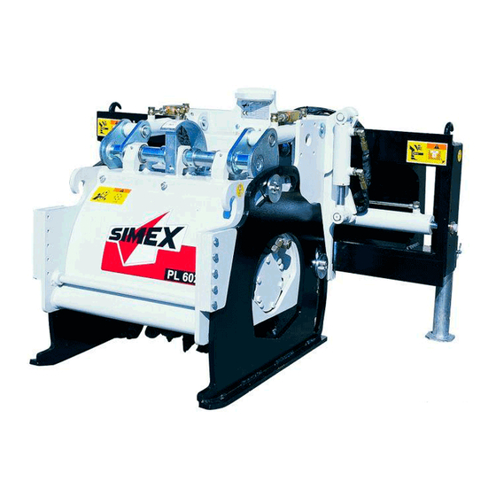
COLD PLANER
SIMEX s.r.l.
Via Newton,31
40017 - San Giovanni in Persiceto (BO) Italy
Tel +39.051.6810609 fax +39.051.6810628
www.simex.it - simex@simex.it
Code: SXNM153D07 (
Type:
.................................(C.A.T.)
Serial n° ..........................
)
English
Advertisement
Table of Contents

Summary of Contents for Simex PL 4520
- Page 1 USE AND MAINTENANCE MANUAL COLD PLANER PL 4520 - PL 5020 - PL 5520 - PL 6020 - PL 7520 SIMEX s.r.l. Via Newton,31 40017 - San Giovanni in Persiceto (BO) Italy Tel +39.051.6810609 fax +39.051.6810628 www.simex.it - simex@simex.it...
-
Page 2: Table Of Contents
TABLE OF CONTENTS Sound power levels detected ........................ 4 Declaration of conformity ........................5 Symbols ..............................6 Safety and hazard stickers ........................7 General precautions for use ........................9 Technical characteristic ........................10 Machine description ..........................10 Overall dimensions ..........................11 Specifications and performance ...................... - Page 3 10.8 Depth adjustment mechanism lubrication ................... 41 10.9 Shock absorber lubrication ........................42 10.10 Lubrication of the depth adjustment shaft mounts ................42 10.11 Hose inspection ........................... 43 10.12 Drain line safety cap check ......................... 43 11 Storage instructions ........................... 44 12 Recommissioning ............................
-
Page 4: Sound Power Levels Detected
Dear Customer, Thank you for choosing a “SIMEX s.r.l.” product! We are pleased to give you this manual, which we hope will help you get the most out of our product and enhance your work. Inside this manual the user will find all the information required to use the machine correctly. The trade name of the machine is stated on the front cover of this manual. -
Page 5: Declaration Of Conformity
2. Declaration of conformity The declaration of conformity is filled in and signed by SIMEX S.r.l.’s legal representative, and attached to this manual. Following an example of the declaration of conformity. -
Page 6: Symbols
3. Symbols The chart below outlines the symbols used in this handbook (those considered the most important). WARNING – HAZARD: this alerts the user to situations or problems which could either jeopardise personal safety or lead to fatal injuries. IMPORTANT: this alerts the user to situations or problems linked to machine efficiency rather than safety. -
Page 7: Safety And Hazard Stickers
4. Safety and hazard stickers Location of the data plate and the safety and hazard stickers on the machine. Warning: RISK OF CRUSHING STICKER; DO NOT ACCESS THE AREA OF RISK Code: 20937 Warning: NO WORK MAY BE CARRIED OUT ON MACHINE UNTIL DRUM... - Page 8 4 stickers HOOK UP POINT FOR LIFTING PURPOSES Code: 20941 Affixed to both sides of Warning: the machine CUTTER DRUM ROTATING Warning: Code: 74796 KEEP CLEAR OF THE MACHINE (MIN. 10 m) Code: 75572 Always heed the warnings on the plates and transfers/stickers. Failure to do so may result in death or serious injury.
-
Page 9: General Precautions For Use
5. General precautions for use • The operator is directly accountable for the machine’s safe operation. • Read this manual carefully before proceeding with installation, start-up, use or any servicing of the machine. • The aim of this handbook is to familiarise the operator, through the figures and explanations, with the basic rules and criteria to follow during machine use and maintenance. -
Page 10: Technical Characteristic
6. Technical characteristic Machine description The Self-levelling Planer, hereinafter referred to as the ‘machine’, is a cold planer for working on flat surfaces made of asphalt or concrete. It can be fitted onto the majority of skid steer loaders, and is ideal for lengthwise trench cutting on horizontal ground. -
Page 11: Overall Dimensions
Overall dimensions 4520 1680 1180 1270 5020 1680 1250 1350 5520 1680 1180 1270 6020 1680 1250 1350 7520 1680 1300 1400 (*) Version with water tank mounted on side shift unit. -
Page 12: Specifications And Performance
Specifications and performance Models Unit of Technical characteristic measurement PL 4520 PL 5020 PL5520 PL 6020 PL 7520 300÷160 300÷160 300÷160 300÷160 300÷180 Operating pressure 65÷140 90÷160 70÷140 90÷160 110÷180 Required oil flow l/min 150÷230 130÷200 150÷230 130÷200 120÷190 Drum speed Max. -
Page 13: Main Machine Parts
Main machine parts 1. Cutter drum; 2. LH work depth adjustment screw; 3. RH work depth adjustment screw; 4. Skids; 5. Hydraulic motor; 6. Drum inspection cover; 7. Side shift; 8. Side shift hydraulic cylinder; 9. Transversal tilt signal light; 10. -
Page 15: Environmental Conditions
(min 200 lux) either by the prime mover or by working area fir o mobile lights. SIMEX S.r.l. cannot be held responsible for any mishandling of the machine or any changes or alterations made to it. -
Page 16: Safety Devices
Safety devices • The safety guards must NEVER be tampered with. • The machine must NEVER be used without the safety guards fitted. • Use always suitable PPE for any maintenances’ operation. • The working tools (teeth) while working can reach an high temperature level. Before touch the working tools (teeth) wait until they cool down and suitable protection gloves MUST be used. -
Page 17: Delivery And Unloading
If, upon delivery, major damage caused during transportation is noted, or any parts that should be included are found to be missing, SIMEX s.r.l. must be notified of the situation promptly. It is also essential to check the equipment delivered against the information given in the itemised shipping document. -
Page 18: Handling, Transportation And Lifting
8 Handling, transportation and lifting If the type approval of the prime mover to travel on normal roads does not extend to the machine, it must be removed before transportation on open roads. Only small movements may be performed on the worksite when the machine is mounted on the prime mover;... -
Page 19: Use
9 Use The fitter is responsible for checking that the prime mover meets the equipment’s specifications (see section 6.3). The machine may only be fitted on prime movers carrying a declaration of conformity to directive 98/37/EC and or 2006/42/EC (e.g. those fitted with dead-man’s controls, which disable the machine’s controls when, for example, there is no-one in the driving seat, etc). -
Page 20: Machine/Prime Mover Matching
Machine/prime mover matching The machine must be mounted on the prime mover’s arm instead of the standard bucket, using any of a number of connection types. Apart from the general instructions given below, the procedures outlined in the prime mover’s manual (see specific section on the application of equipment) must also be followed. Example of the operations that must be carried out for a standard coupling : 1- Position the self-levelling planer on flat, compact ground, in the non-operative position,... - Page 21 4- Get off the prime mover (see para. 9.2) and, after switching it off and removing the ignition keys, push the two levers (figures 4 and 5 opposite) to engage the quick coupling lock pins. Check that the levers are locked in the retaining position and that the pins are fitted properly inside the slots on the machine’s coupling.
-
Page 22: Hydraulic Connection Of The Standard Machine With 3-Line Hydraulic System To The Prime Mover
Hydraulic connection of the standard machine with 3-line hydraulic system to the prime mover To connect the hoses, proceed as follows: 1- release the pressure inside the system (see p.m. manual); 2- connect the hoses using the quick coupling fittings (see specific section in para. 9.5); it is compulsory to fit the drain line first (ref. -
Page 23: Hydraulic Connection Of The Standard Machine With 5-Line Hydraulic System To The Prime Mover
Hydraulic connection of the standard machine with 5-line hydraulic system to the prime mover To connect the hoses, proceed as follows: 1- release the pressure inside the system (see p.m. manual); 2- connect the three motor hoses (ref. “1” fig. 5) using the quick coupling fittings (see below); it is essential to insert the drain line first. -
Page 24: Hydraulic Disconnection Of The Standard Machine With 3- Or 5-Line Hydraulic System From The Prime Mover
If using flat-faced quick couplings, proceed as follows (ref. in fig. 6): A- Fit the male section (ref. “7”) into the female section (ref. “8”) until you hear it click into place in the ring nut (ref. “9”); B- Turn the ring nut (ref “9”) so that the notch (ref “10”) is not aligned with the spherule (ref. “11”), thereby preventing accidental disconnection. -
Page 25: Disconnecting The Machine From The Prime Mover
Disconnecting the machine from the prime mover IMPORTANT: Make sure the hydraulic connections between the machine and the prime mover have been disconnected (see para. 9.6) and that the POWER CABLE (if featured) has been DISCONNECTED (para. 9.4). Operations that must be carried out for a standard coupling type (see figures in para. 9.3): •... -
Page 26: Planing Depth Adjustment
Planing depth adjustment IMPORTANT: To adjust the planing depth correctly, keep the machine lifted slightly off the ground when making adjustments. 1- Release the depth adjustment lock: Release the depth adjustment lock as shown in fig. 1. fig. 1 2- Insert the crank (supplied) and turn it to adjust the planing depth, as show in fig. -
Page 27: Setting The Zero Position For Planing Depth Adjustment
9.8.1. Setting the zero position for planing depth adjustment If shallow planing is required, which therefore entails greater accuracy, the zero position on the measuring rod can be set according to the level of the ground where the planing is required. The following operations must be carried out: 1- Following the procedure outlined in paragraph 9.8, set the planing depth at the minimum (tighten both depth adjustment screws fully);... -
Page 28: Cutter Drum Removal And Refitting
Cutter drum removal and refitting The drum replacement stage can be performed either with the machine mounted on the prime mover or lifted slightly off the ground and secured using suitable lifting equipment. Place props under the machine to prevent it lowering if the valve or any other components on the prime mover arm give way. -
Page 29: Mechanical Floating Tilt Device With Spring Jack
9.10 Mechanical floating tilt device with spring jack The cutting section of the machine (ref. “a” in fig. 6) adapts itself perfectly to the slope of the surface due to be planed, thanks to a system which “releases” it from the side shift. This side shift, on the other hand, maintains the same angle of inclination as the prime mover (fig. -
Page 30: Starting Up Standard Machines
The device described on the previous page also allows the machine to carry out sloped planing (fig. 10). This is done by setting the RH and LH depth adjustment screws at different work depths, until the desired angle is obtained, and using the measuring scale to check the angle (fig. 7). ... - Page 31 b- Standard machines featuring 3 hydraulic lines The machine can only be activated (i.e. cutter drum start rotating) using the controls on the prime mover. Carry out the operations listed below: 1- switch on the prime mover engine and wait a while, with the engine running, so that the oil reaches optimal temperature and any air bubbles present in the hydraulic system are expelled;...
-
Page 32: Side Shift Operation On The Standard Machine With 3-Line Hydraulic System
9.12 Side shift operation on the standard machine with 3-line hydraulic system To activate the side shift, proceed as follows: 1- deactivate the drum by flipping the switch (ref. “A” in the figure) to OFF and check that the red LED is off (ref. -
Page 33: General Operating Conditions
9.13 General operating conditions A- Adjust the planing depth, as outlined in para. 9.8; B- Move the machine (self-levelling planer) over to the work equipment (fig. 1). Try to keep the machine as central as possible in relation to the side shift to ensure better balance overall, and then lower the machine so it is a few centimetres off the ground;... -
Page 34: Side-By-Side Planing
9.14 Side-by-side planing If the area where planing is required is larger than the width of the cutter drum, several strips of planing can be carried out side by side: align the machine and the p.m. in preparation for the next planing strip, positioning the planer –... -
Page 35: Stopping The Machine In Normal Conditions
9.15 Stopping the machine in normal conditions To stop the machine in normal conditions, proceed in one of two ways: 1- using the prime mover controls, reduce the diesel engine speed so that the engine is idling and switch off the hydraulic oil flow; 2- deactivate the drum by flipping the switch on the control unit (featured on the machines with 3 hydraulic lines) to OFF. -
Page 36: Maintenance
10 Maintenance 1. All maintenance work on the machine, as well as inspections and cleaning, must be carried out with the machine detached from the prime mover and positioned on the ground (for designated worker, see the maintenance schedule); 2. Maintenance operations must be carried out in a suitable place, in compliance with the safety regulations in force;... -
Page 37: Cutter Drum Inspection
10.1 Cutter drum inspection The cutter drum (see para. 6.4 ref. “1”) is essentially the heart of the machine. Because of the type of work it does, it is easily damaged. Inspect the drum visually if it has hit solid objects such as: manhole covers, iron obstructions, etc. Never work with damaged and/or missing teeth. -
Page 38: Tool Integrity Assessment (Teeth)
10.2 Tool integrity assessment (teeth) Before leaving the operator’s seat on the prime mover, make sure the area is flat, the prime mover is stabilised, the machine is resting on the ground, and the keys have been removed from the ignition. Every tooth is subject to constant wear due to contact with the material cut. - Page 39 Assessment procedure: 1- visual inspection to establish degree of wear; 2- check teeth rotate in their seats, as shown in fig. 1 below. Following the assessment, replace any broken tools or those showing excessive wear (as outlined in para. 10.3) or clean the seats of the teeth that are completely jammed, as explained below. Tooth cleaning: 1- remove the tooth that does not turn (see para.10.3);...
-
Page 40: Tool Replacement (Teeth)
10.3 Tool replacement (teeth) Removal stage: The teeth are held in the tooth holder by a retainer spring. Position one of the special spanners (ref. "2") supplied with the machine as shown in the figure. Strike the key with a hammer and remove the tooth (ref. -
Page 41: Check The Support Skids For Wear
10.7 Check the support skids for wear Inspect the two support skids visually for wear (see figure below). For all special maintenance, contact the dealer from whom you purchased the machine. 10.8 Depth adjustment mechanism lubrication Using the greasing nipples shown opposite, grease the two depth adjusters. -
Page 42: Shock Absorber Lubrication
10.9 Shock absorber lubrication Grease using the greasing nipples shown opposite. 10.10 Lubrication of the depth adjustment shaft mounts Grease using the greasing nipples shown opposite. Do not overlubricate as the excess grease would trap in dust. -
Page 43: Hose Inspection
10.11 Hose inspection Check the seam fastening the fitting to the hoses and check the condition of the hoses. If a hose shows signs of leaks, breakages, swellings, abrasions, etc., it must be replaced. Warnings concerning hose replacement: 1. Clean the area concerned to stop dirt getting in the hydraulic circuit. 2. -
Page 44: Storage Instructions
13 Spare parts and accessories Contact an authorised SIMEX s.r.l. dealer. 14 Disposal When disposing of the machine or its parts (oils, hoses, plastic parts, etc.), always comply... -
Page 45: Troubleshooting
SCREWS/ BOLTS (DRUM, HYDRAULIC MOTOR, ETC) REPLACE THE MISSING SCREWS/BOLTS. VIBRATIONS WORN OR MISSING TOOLS REPLACE THE TOOLS AND CLEAN THEIR SEATS CUTTER HYDRAULIC CONTACT AN AUTHORISED SIMEX SERVICE MOTOR NOISY OR PROBLEMS INSIDE THE MOTOR CENTRE JAMMED NO HYDRAULIC FLOW AND/OR PRESSURE CHECK THE PRIME MOVER’S HYDRAULIC SYSTEM... - Page 46 CONTACT AN AUTHORISED SIMEX SERVICE SEALS CENTRE ALWAYS CONNECT THE DRAIN LINE DIRECTLY TO DRAIN LINE MISSING THE PRIME MOVER AND CONTACT A SIMEX OR NOT FITTED ON AUTHORISED SERVICE CENTRE TO HAVE THE CAP THE PRIME MOVER AND O-RING REPLACED AND THE CORRECTLY COUNTERPRESSURE CHECKED (LIMIT = <...
-
Page 47: Optionals
16 Optionals When fitting accessories, making adjustments and replacing parts on the accessories, always work with the machine stopped, the parking brake engaged and the ignition key removed. Use suitable handling and lifting equipment to avoid risks of accidents caused by manual load handling. -
Page 48: Removable Skid
The machine can be supplied on request with a removable skid, which is recommended for jobs where planing is required up to the edge of pavements, etc. Skid dimensions MODEL PL 4520 PL 5520 PL 6020 Key: Slitta = skid... -
Page 49: Misting Unit
Where there is a Simex electrical system featured, with an electrical panel fitted in the p.m. cab, switch A on the panel shown in fig. 1 (located inside the prime mover) allows operation of the electric pump for the forced mist to be directed at the cutter drum. -
Page 50: Hydraulic Tilt Adjustment
16.4 Hydraulic tilt adjustment On request, the hydraulic tilt adjustment can be operated via the jack shown in fig. 2. For the machines featuring 3 hydraulic lines: The jack (fig. 2) that controls the tilt angle is operated using the controls on the panel in figure 1: - deactivate the drum by flipping the switch (ref. -
Page 51: Hydraulic Depth Adjustment
For the machines featuring 5 hydraulic lines: The jack (fig. 2, previous page) that controls the tilt, is activated using a combination of the control located on the panel in figure 3 and the control located in the prime mover (the second auxiliary device control, not the high flow control). - Page 52 For the machines featuring 5 hydraulic lines. The jacks (fig. 3) that control the planing depth, are activated using a combination of the control located on the panel in figure 2 and the control located in the prime mover (the second auxiliary device control). Depending on the jack required, keep button C pushed either to the right or the left, activating the prime mover control at...
-
Page 53: Charts
17 Charts 17.1 Maximum screw tightening torques SCREW SCREW DIAMETER - TORQUE (Nm) – 0.10 FRICTION COEFFICIENT CLASS 1150 10.9 1200 1600 12.9 1400 1950 Fitting advice The screws must be lubricated with engine oil; For parts fastened with two or more screws, the screws must be tightened progressively and alternately until the prescribed torque is reached;... -
Page 54: Guarantee
During the guarantee period, the SIMEX authorised dealer or any other authorised service centre, will repair or replace, solely in accordance with SIMEX’s instructions, any part found to be faulty as a result of a manufacturing flaw or defect. SIMEX’s duties are limited to: supplying the parts needing replacement, free of charge;... -
Page 55: Control Circuit Diagrams
19 Control circuit diagrams HYDRAULIC DIAGRAMS: 3-hydraulic line version Key: AUX= ‘High Flow’ auxiliary control M = Motor T= Hydraulic shifting Pdx= RH hydraulic depth Pdx= LH hydraulic depth I= Hydraulic tilt F= Hydraulic floating tilt 5-hydraulic line standard version Key: AUX1= ‘High Flow’... - Page 56 5-hydraulic line version with full optionals Key: AUX1= ‘High Flow’ auxiliary control AUX2= Auxiliary control for connected lines M = Motor T= Hydraulic shifting Pdx= RH hydraulic depth Psx= LH hydraulic depth I= Hydraulic tilt...
- Page 57 WIRING DIAGRAM FOR 3-HYDRAULIC LINE VERSION Key: = Floating tilt = Drum activation = Jack activation = Water WIRING DIAGRAM FOR 5-HYDRAULIC LINE VERSION WITH OPTIONALS...
- Page 58 NOTES: _______________________________________________________________________________________ _______________________________________________________________________________________ _______________________________________________________________________________________ _______________________________________________________________________________________ _______________________________________________________________________________________ _______________________________________________________________________________________ _______________________________________________________________________________________ _______________________________________________________________________________________ _______________________________________________________________________________________ _______________________________________________________________________________________ _______________________________________________________________________________________ _______________________________________________________________________________________ _______________________________________________________________________________________ _______________________________________________________________________________________ _______________________________________________________________________________________ _______________________________________________________________________________________ _______________________________________________________________________________________ _______________________________________________________________________________________ _______________________________________________________________________________________ _______________________________________________________________________________________ _______________________________________________________________________________________ _______________________________________________________________________________________ _______________________________________________________________________________________...
- Page 59 NOTES: _______________________________________________________________________________________ _______________________________________________________________________________________ _______________________________________________________________________________________ _______________________________________________________________________________________ _______________________________________________________________________________________ _______________________________________________________________________________________ _______________________________________________________________________________________ _______________________________________________________________________________________ _______________________________________________________________________________________ _______________________________________________________________________________________ _______________________________________________________________________________________ _______________________________________________________________________________________ _______________________________________________________________________________________ _______________________________________________________________________________________ _______________________________________________________________________________________ _______________________________________________________________________________________ _______________________________________________________________________________________ _______________________________________________________________________________________ _______________________________________________________________________________________ _______________________________________________________________________________________ _______________________________________________________________________________________ _______________________________________________________________________________________ _______________________________________________________________________________________...
- Page 60 IMPORTER...
Need help?
Do you have a question about the PL 4520 and is the answer not in the manual?
Questions and answers
Come abbassare fresa