Advertisement
Quick Links
1.1 General
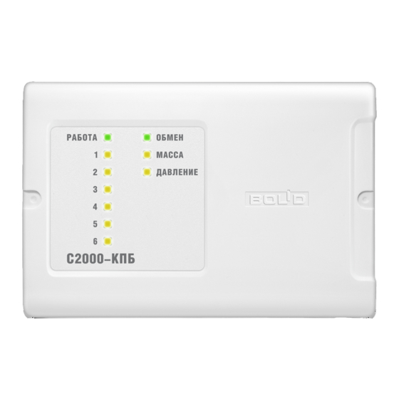
1.2 1. This Instruction Manual describes how to operate and maintain the S2000-KPB Executive
Unit of version 3.02 (hereinafter referred to as the unit).
1.2 2. The unit is designed to be used with an S2000M panel, an S2000-ASPT fire alarm and
extinguishing control unit, or a PC as a component of modular control and indicating equipment in
such system as a fire / intrusion / panic alarm system, a voice alarm and evacuation system, a fire
suppression system, an access control system, or a CCTV system.
1.2 3. The unit is designed to control executive devices (light panels, light alarms, sirens, video
cameras, electromagnet locks etc.) as well as clean agent suppression systems and fire-fighting
equipment in gas, dry powder, and aerosol fire-fighting systems. The unit controls executive devices
by switching voltage from its power input terminals U
external power supplies to output terminals is prohibited and can damage the unit.
1.2 4. The unit is designed to be installed on a vertical surface inside the protected premises
closely to the executive devices. The unit is designed for round-the-clock operation.
1.2 5. The unit must not be used in aggressive medium or dust condition, or in explosion-
hazardous premises.
1.2 6. As to the resistance to mechanical stress, the unit falls in the placement category 03 of ОСТ
25 1099-83.
1.2 7. As to immunity to climate effects of environment, the unit corresponds to version 03 in
accordance with ОСТ 25 1099-83 but for ambient temperatures from minus 30 to +55°С.
1.2 Specifications
1.2 1. Power Supply:
1.2 2. Power Inputs:
1.2 3. Consumed Current
(without executive devices):
1.2 4. Outputs:
− Switching Voltage:
− Switching Current:
− Circuit Failure Monitoring Current:
1.2 5. Max Total Switched Current of the Unit:
1.2 6. Inputs:
1.2 7. Resistance of the loop wires
without termination resistance:
1.2 8. Leakage resistance between the loop wires
or each wire and ground:
1.2 9. Overall Dimensions:
1.2 10. Weight:
S2000-KPB
EXECUTIVE UNIT
Version 3.02
INSTRUCTION MANUAL
1
TECHNICAL DESCRIPTION
and U
to its output terminals. Connecting
main
back
An external dc power supply with power
voltage between 10.2 V dc and 28.4 V dc
(RIP-12, RIP-24)
Two
100 mA max
Six
10.2 dc to 28.4 V dc (from the power
supply of the unit) ;
5 mA ÷ 2.5 A;
1.5 mA max
6 A
Two
100 Ohm max
At least 50 kOhm
156 mm × 107 mm × 39 mm max
0.3 kg max
1
Advertisement

Related Manuals for bolid S2000-KPB


Summary of Contents for bolid S2000-KPB
- Page 1 TECHNICAL DESCRIPTION 1.1 General 1.2 1. This Instruction Manual describes how to operate and maintain the S2000-KPB Executive Unit of version 3.02 (hereinafter referred to as the unit). 1.2 2. The unit is designed to be used with an S2000M panel, an S2000-ASPT fire alarm and...
- Page 2 Russian Standard ГОСТ 12.1.004-91. 1.2 16. The content of precious materials: no need to account for the storage, disposal and recycling. 1.3 Standard Delivery 1) S2000-KPB Executive Unit – 1 pc. 2) Instruction Manual – 1 pc.
- Page 3 Figure 1. The States of the Inputs and the Threshold Values of Resistance The current states of the first and the second inputs are indicated by the MASS and PRES indicators. Table 1 demonstrates the states an input can enter, the indication patterns of the unit, and the times of transition.
- Page 4 State LED Color Indicator Performance Transition Time Four flashes for Addressable Loop Parameter Error Amber 125 ms Immediately every 2 s (0 second) Disarmed Amber Lit steady The unit provides disabling an input by a disarm command which should be given to the unit from the network controller with specifying the number of the input.
- Page 5 The full list of output executive commands can be seen in the User’s Manual for an S2000M panel. When the S2000-KPB is connected to the internal interface RS-485-2 of an S2000- ASPT unit, the first one is used to expand the discharge circuits of the last one. In this case the individual outputs of the unit cannot be controlled remotely from the S2000M panel.
- Page 6 When release circuits or explosion protected devices are being connected to the S2000-KPB then the load connection modules can be located in the vicinity of the connected devices. An example of connection diagram is shown in Figure 3. The monitored states of a monitored circuit are defined by the circuit failure detection type specified in the configuration parameters in accordance with Table 3.
- Page 7 o For the Periodic Load Shutdown monitoring type the minimum current for the output is 5mA. Once per 30 seconds the unit will shut the load down for 125 ms when it will be inspecting integrity of the line up to the termination element (the load connection module) of the monitored circuit. o For the Current Drop Monitoring type the unit, switching the output on, accumulates the average value of the current in the monitored circuit.
- Page 8 The unit monitors the total operating current of all the monitored circuits. If the total operating current has exceeded the maximum permitted value (6 Amperes) the unit generates an Overcurrent message and shuts off one-by-one the outputs with the maximum operating current. As soon as the total current doesn’t exceed the maximum permitted value the unit generates a Power Restored message.
- Page 9 If the unit enters the Device Failed mode on switching on, update its firmware as discussed in Section 3.4 or return the unit to the manufacturer. Communicating Data Over the RS-485 Interface The unit receives commands from and transmits messages to the network controller over the RS- 485 interface.
- Page 10 Programming the Unit To be adjusted for a specific way to use, the unit provides programming the following parameters which are stores in its non-volatile memory. The configuration parameters are described in Table 9. Table 9. Configuration Parameters Parameter Description Value Default Value Parameters of Outputs...
- Page 11 To change configuration parameters of the unit, an x86-compatible PC under Windows XP or higher and one of the Bolid manufactured interface converters (such as PI-GR, S2000-PI, S2000-USB etc.) are to be used. The configuration parameters are changed by means of UProg Configuration Tool of version 4.1.0.51 or higher.
- Page 12 4. If an output is not in use, a 1kOhm - 0.5 W resistor can be used instead of the load connection module. 5. Normally open and normally closed detectors can be combined and brought into the same circuit if only one detector can be in activated status at the same time. Figure 3. S2000-KPB Wiring Diagram...
-
Page 13: Performance Instructions
Figure 4. The Diagram for Connecting Several Light Signs to the Same Output PERFORMANCE INSTRUCTIONS When you select a power supply be sure it can provide the electric current enough to power all the executive devices connected to the unit. The power supply should be located at such distance from the unit that the resistance R the wires between the power supply and the unit (see Figure 5) meets the following requirements: –... -
Page 14: Maintenance
[Ohm] (see Clause 4.2); stands for the resistance of wires between the S2000-KPB and the fixed fire-fighting system, [Ohm] (see Clause 4.2); stands for the effective resistance of the exploder (bridgewire), [Ohm]. - Page 15 How to generate the command or call the event to activate the control command for each used output. 5.3.2 Open the cover of the S2000-KPB unit removing the tamper label if necessary. 5.3.3 WARNING: If the unit is connected to clean agent suppression modules or other executive devices which must not be activated during the inspection, carry out the steps 5.3.4 –...
- Page 16 ”. main back 5.3.21 Connect the circuits to the outputs of the S2000-KPB unit as specified by the design documentation. 5.3.22 Switch on the battery backed power supplies connected to the unit or connect the power circuits to the contacts «+U »...
-
Page 17: Overall And Mounting Dimensions
OVERALL AND MOUNTING DIMENSIONS ZAO NVP Bolid, 4 Pionerskaya Str., Korolev 141070, Moscow Region, Russia Phone/fax: +7 495 775-7155 Email: info@bolid.ru Technical Support: support@bolid.ru http://bolid.ru...
Need help?
Do you have a question about the S2000-KPB and is the answer not in the manual?
Questions and answers