Table of Contents
Advertisement
Quick Links
SPECIFICATIONS ...............................................................................................................................................................2
VOLTAGE SELECTION .......................................................................................................................................................2
AC POWER SUPPLY CORD AND PLUG ............................................................................................................................2
NAMES OF PARTS ..............................................................................................................................................................3
FITTING OF DIAL POINTER ...............................................................................................................................................3
DISASSEMBLY ....................................................................................................................................................................4
REMOVING AND REINSTALLING THE MAIN PARTS .......................................................................................................5
ADJUSTMENT .....................................................................................................................................................................6
SCHEMATIC DIAGRAM / WIRING SIDE OF P.W.BOARD .................................................................................................8
NOTES ON SCHEMATIC DIAGRAM .................................................................................................................................12
TYPES OF TRANSISTOR AND LED .................................................................................................................................12
REPLACEMENT PARTS LIST / EXPLODED VIEW
All manuals and user guides at all-guides.com
SERVICE MANUAL
CONTENTS
SHARP CORPORATION
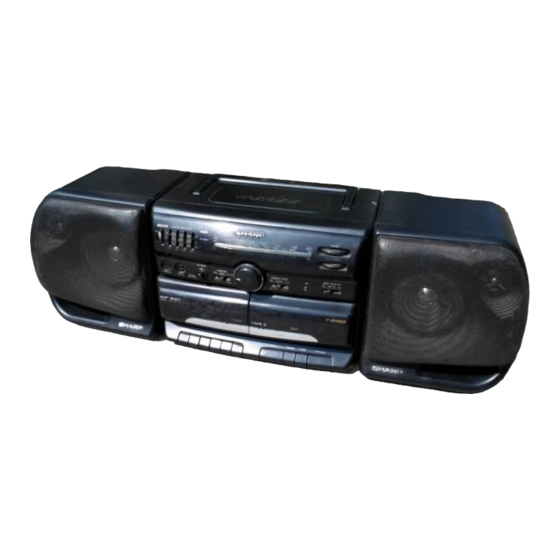
WF-930Z(BK)
• In the interests of user-safety the set should be restored to its
original condition and only parts identical to those specified
should be used.
WF-930Z
No. S5630WF930Z//
Page
Advertisement
Table of Contents

Related Manuals for Sharp WF-930ZBK


Summary of Contents for Sharp WF-930ZBK
-
Page 1: Table Of Contents
FITTING OF DIAL POINTER ...............................3 DISASSEMBLY ..................................4 REMOVING AND REINSTALLING THE MAIN PARTS .......................5 ADJUSTMENT ..................................6 SCHEMATIC DIAGRAM / WIRING SIDE OF P.W.BOARD ....................8 NOTES ON SCHEMATIC DIAGRAM ..........................12 TYPES OF TRANSISTOR AND LED ..........................12 REPLACEMENT PARTS LIST / EXPLODED VIEW SHARP CORPORATION... -
Page 2: Specifications
All manuals and user guides at all-guides.com WF-930Z FOR A COMPLETE DESCRIPTION OF THE OPERATION OF THIS UNIT, PLEASE REFER TO THE OPERATION MANUAL. SPECIFICATIONS Tape recorder section General Frequency response: 60 - 12,000 Hz (Normal tape) Power source: AC 110 - 127/220 - 240 V, 50/60 Hz Signal/noise ratio: 40 dB (TAPE 1, recording/playback) DC 12 V ["D"... -
Page 3: Names Of Parts
All manuals and user guides at all-guides.com WF-930Z NAMES OF PARTS 2 3 4 5 6 7 8 9 1. Extra Bass Control: X-BASS 2. Graphic Equalizer Controls 3. FM Stereo Indicator 4. Power Indicator 5. Function Selector Switch 6. Volume Control 7. -
Page 4: Disassembly
All manuals and user guides at all-guides.com WF-930Z DISASSEMBLY Caution on Disassembly Follow the below-mentioned notes when disassembling the unit and reassembling it, to keep it safe and ensure excellent Main (A2) x2 performance: 1. Take cassette tape out of the unit. ø3 x10mm (A7) x1 2. -
Page 5: Removing And Reinstalling The Main Parts
All manuals and user guides at all-guides.com WF-930Z REMOVING AND REINSTALLING THE MAIN PARTS (A1) x1 TAPE 1 ø2x7mm (A1) x1 TAPE MECHANISM SECTION Hook ø2x3mm (A2) x2 Perform steps 1, 2 and 5 of the disassembly method to remove Record/Playback the tape mechanism. -
Page 6: Adjustment
All manuals and user guides at all-guides.com WF-930Z ADJUSTMENT MECHANISM SECTION TUNER SECTION fL: Low-range frequency • Driving Force Check fH: High-range frequency Torque Meter Specified Value • AM IF/RF Play: TW-2412 Tape 1: Over 50g Tape 2: Over 60 g Specified Instrument Value/Adjusting... - Page 7 All manuals and user guides at all-guides.com WF-930Z TRACKING TRACKING SW2 BAND TRACKING COVERAGE TRACKING SW1 BAND COVERAGE AM IF MW BAND COVERAGE FM IF FM DETECTION MAIN PWB FM BAND COVERAGE MAIN PWB TAPE SPEED Figure 7-1 ADJUSTMENT POINTS VR501 CNP501 IC401...
-
Page 8: Schematic Diagram / Wiring Side Of P.w.board
All manuals and user guides at all-guides.com WF-930Z RF AMP. TRACKING TRACKING TRACKING FM BAND PASS TA7378P FILTER FM FRONT END FM/SW BPF1 FM BAND MW BAND SW1 BAND ROD ANTENNA COVERAGE COVERAGE COVERAGE BAND 1 2 3 SELCTOR FM IF SW1G (CH) (CH) - Page 9 All manuals and user guides at all-guides.com WF-930Z MIC REC : < > HI-SPEED DUBBING : ( TRACKING TRACKING IC401 IC101 IC251 VOLTAGE VOLTAGE VOLTAGE VOLTAGE VOLTAGE VOLTAGE VOLTAGE VOLTAGE SW2 BAND SW2 BAND 0.7V 1.6V 1.7V 1.1V 4.3V COVERAGE COVERAGE 4.3V 1.4V...
- Page 10 All manuals and user guides at all-guides.com WF-930Z CNS502 GRAPHIC EQUALIZER PWB-B VR255 C274 VR255 X-BASS SW502 SW503 SW501 C270 TAPE1 TAPE2 TAPE2 C269 VR254 MAIN PLAY MAIN VR254 330Hz M501 C266 TAPE C265 MOTOR VR253 VR253 C254 1kHz TAPE1 C262 C261 VR252...
- Page 11 All manuals and user guides at all-guides.com WF-930Z MAIN PWB-A1 R415 J401 SPEAKER R416 TERMINALS C414 MIC101 R505 BUILT-IN MICROPHONE Q503 CB E CNP503 L-CH C416 C505 Q502 CB E R140 C504 R141 C413 TAPE SPEED R414 12 11 10 9 8 7 6 5 4 3 2 1 R413 Q101 C503...
-
Page 12: Notes On Schematic Diagram
All manuals and user guides at all-guides.com WF-930Z NOTES ON SCHEMATIC DIAGRAM • Resistor: • The indicated voltage in each section is the one measured by To differentiate the units of resistors, The symbol as K and Digital Multimeter between such a section and the chassis M are used: the symbol K means 1000 ohm and the symbol with no signal given. - Page 13 “HOW TO ORDER REPLACEMENT PARTS” To have your order filled promptly and correctly, please furnish the For U.S.A. only following information. Contact your nearest SHARP Parts Distributor to order. 1. MODEL NUMBER 2. REF. No. 3. PART NO. 4. DESCRIPTION For location of SHARP Parts Distributor, Please call Toll-Free;...
- Page 14 All manuals and user guides at all-guides.com WF-930Z PRICE PRICE PART CODE DESCRIPTION PARTS CODE DESCRIPTION RANK RANK INTEGRATED CIRCUITS VCCCPU1HH3R0C J AA 3 pF (CH),50V VCCCPU1HH150J AA 15 pF (CH),50V AA 0.02 µF,50V 9FGS3200737872 AE FM Front End,TA7378P VCKZPU1HF203Z C10,11 VCCCPU1HH5R0C J AA 5 pF (CH),50V...
- Page 15 All manuals and user guides at all-guides.com WF-930Z PRICE PRICE DESCRIPTION DESCRIPTION PART CODE PARTS CODE RANK RANK AE 2200 µF,25V,Electrolytic C419 RC-GZW228AF1E R522 VRD-ST2EE471J AA 470 ohms,1/4W AB 22 µF,25V,Electrolytic C420 RC-GZA226AF1E AA 0.02 µF,50V OTHER CIRCUITRY PARTS C502 VCKZPU1HF203Z AB 220 µF,10V,Electrolytic C503...
- Page 16 AC Bracket,Volume PWB 9FG10295070080 AA Gear,Cassette Holder 9FGS5640012001 AA Terminal,Main PWB 9FG19593160003 AA Stand Pad,Rear Cabinet 9FG10395070030 AA Decoration Panel,Dial Pointer 9FG10195070100 AA SHARP Badge 9FGS9851820001 AD Cord,Speaker 9FG10495070160 AA Knob [Volume Control] 9FG10295080010 AA Holder,Speaker Cord 9FG13295070010 AC Holder,Volume Knob 9FG10195080015 AH Front Panel Ass’y,Speaker,Left...
- Page 17 All manuals and user guides at all-guides.com WF-930Z PRICE PRICE DESCRIPTION DESCRIPTION PART CODE PARTS CODE RANK RANK 9FG20595070010 Packing Case 9FG20895080002 Label,Bar Code 9FG20895080003 Label,Feature 9FG21102850030 Polyethylene Bag,AC Power Supply Cord 9FG21194080040 Polyethylene Bag,Operation Manual 9FG21195070010 Polyethylene Bag,Speaker 9FG21195070020 Polyethylene Bag,Unit 9FG21195070030 Polyethylene Bag,AC Power...
- Page 18 All manuals and user guides at all-guides.com WF-930Z TAPE 1 TAPE 2 SW501 SW502 SW503 57x3 60x2 72x2 56x3 74x2 74x2 72x2 60x2 M501 BELT CONNECTION TAPE 2 Motor TAPE 1 Figure 5 MECHANISM EXPLODE VIEW – 5 –...
- Page 19 All manuals and user guides at all-guides.com WF-930Z 604x2 611x3 274x3 610x2 610x2 278x2 T601 613x2 604x2 233x2 TAPE MECHANISM PWB-A4 606x5 606x2 285x4 609x4 Silicon Grease 240x2 609x4 605x6 606x2 IC401 254 255 614x2 PWB-B 241x2 VR401 PWB-A1 PWB-A3 PWB-A2 with VR401 PWB-C...
- Page 20 612x4 TWEETER SP703(L-CH) SP704(R-CH) WOOFER SP701(L-CH) SP702(R-CH) LEFT : 305 RIGHT : 306 607x4 A9606-2260NS·TI·C Printed in Japan EX·SZ Figure 7 SPEAKER EXPLODED VIEW Writer and Editor: Quality & Reliability Control Center of Communication & Audio System Group, Sharp Corp.