Table of Contents
Advertisement
Quick Links
Advertisement
Table of Contents

Related Manuals for Fujitsu PRIMERGY TX300 S3


Summary of Contents for Fujitsu PRIMERGY TX300 S3
- Page 1 PRIMERGY PRIMERGY TX300 S3 Server Service Supplement Susanne Däschlein Fujitsu Siemens Computers GmbH München 81730 München e-mail: email: manuals@fujitsu-siemens.com Tel.: (089) 61001155 Fax: (++49) 700 / 372 00000 TX300 S3 Sprachen: En Edition August 2006...
- Page 2 Gesellschaft für Technik-Dokumentation mbH www.cognitas.de Copyright and Trademarks Copyright © 2006 Fujitsu Siemens Computers GmbH. All rights reserved. Delivery subject to availability; right of technical modifications reserved. All hardware and software names used are trademarks of their respective manufacturers.
-
Page 3: Table Of Contents
Contents Introduction ......5 Overview of the documentation ....5 Notational conventions . -
Page 5: Introduction
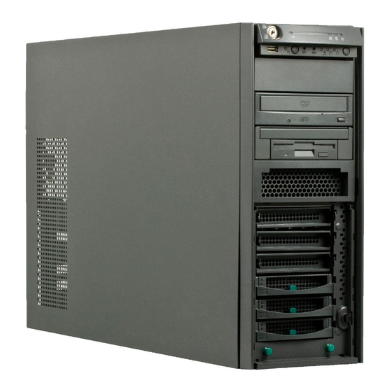
Introduction The PRIMERGY TX300 S3 Server is an Intel-based server for medium-sized and large networks. The server is suitable for use as a file server as well as an application, information, or Internet server. It is available as a floorstand or rack model. - Page 6 Overview of the documentation Introduction Information/procedure Manual Detailed safety notes Safety Features and technical data of the server Operating Manual Installation and operation, among other things: – External ports – Operation – Configuration of the server – Installation of the rack mounting kit Troubleshooting Installation/removal of all hot-plug components: –...
- Page 7 Introduction Overview of the documentation Information/procedure Manual Extensions and upgrades: Options Guide For some components only the installation routine is described in the Options Guide. Removing this components proceed in reverse order. – Extending/replacing the main memory – Installing a second processor / replacing the processor / replacing the heat sink –...
-
Page 8: Notational Conventions
Notational conventions Introduction Notational conventions The following notational conventions are used in this manual: Text in italics indicates commands, menu items or software programs. „Quotation marks“ indicate names of chapters and terms that are being emphasized. Ê describes activities that must be performed in the order shown. -
Page 9: Procedure
Procedure CAUTION! The actions described in these instructions should only be performed by service personnel. Ê First of all please familiarize yourself with the safety instructions in the section chapter “Safety notes” on page 11 et seq. . Ê Ensure that all required manuals (see Service DVD) are available, printing out the PDF files if necessary. -
Page 11: Safety Notes
Safety notes The following safety notes are also provided in the “Safety notes and other important information” manual. This device complies with the relevant safety regulations for data processing equipment. CAUTION! The actions described in these instructions should only be performed by service personnel. - Page 12 Safety notes CAUTION! This device has a specially approved power cable and must only be connected to a grounded insulated socket. Ensure that the power socket on the device or the grounded wall outlet is freely accessible. The ON/OFF button does not disconnect the device from the mains voltage.
- Page 13 Safety notes CAUTION! Proper operation of the device (in accordance with IEC 60950/ EN 60950) is only ensured if the casing is completely assembled and the rear covers for the installation openings have been put in place (electric shock, cooling, fire protection, interference suppression). Only install system expansions that satisfy the requirements and rules governing safety and electromagnetic compatibility and relating to telecommunications terminal equipment.
- Page 14 Safety notes CAUTION! Replace the lithium battery on the system board in accordance with the instructions in the Technical Manual for the system board. All batteries containing pollutants are marked with a symbol (a crossed-out garbage can). In addition, the marking is provided with the chemical symbol of the heavy metal decisive for the classification as a pollutant: Cd Cadmium...
- Page 15 Safety notes Note about the laser The CD-/DVD-ROM drive is classified for laser class 1according to IEC 60825-1. CAUTION! The CD-/DVD-ROM drive contains a laser diode (LED). Sometimes the LED produces a stronger laser beam than laser class 1. Direct view into this laser beam is dangerous.
- Page 16 Safety notes Place all components on a static-safe base. You will find a detailed description for handling ESD components in the relevant European or international standards (DIN EN 61340-5-1, ANSI/ESD S20.20). Service Supplement TX300 S3...
-
Page 17: Replacement Routines
Replacement routines CAUTION! Observe the safety instructions in the chapter “Safety notes” on page 11 et seq. . Preparation 4.1.1 Floorstand model You will find a detailed description of ’Opening the server’ and ’Removing the front cover’ in the Options Guide TX300 S3. 4.1.1.1 Opening the server Ê... -
Page 18: Rack Model
Preparation Replacement routines Ê Pull out the two green locking buttons of the front cover. Ê Pull the front cover forward slightly at the lower edge. Ê Unhook the front cover at the top and remove it. 4.1.2 Rack model You will find a detailed description of ’Opening the server’... -
Page 19: Replacing The Operating Panel
Replacement routines Replacing the operating panel Replacing the operating panel Ê Open the server and remove the front cover or the rack front cover as described in the section “Preparation” on page Figure 2: Removing the operating panel module Ê Press the two metal tongues of the EasyClick rails inward (1) until the locking mechanism is released. -
Page 20: Replacing The Processor Fan Holder
Replacing the processor fan holder Replacement routines Replacing the processor fan holder The processor fan holder consists of the holder, the processor fan backplane and the fan cable. The holder is completely assembled as spare part (see the board layout on page 37). - Page 21 Replacement routines Replacing the Power backplane The Power backplane in the floorstand model is positioned directly under the top cover and it makes sense to lay the server on a table with the uncovered side facing upward. Place the server in such a way that the feet can project over the edge.
- Page 22 Replacing the Power backplane Replacement routines Guides Figure 4: Removing the Power backplane Ê Remove the screw (see the circle). Ê Push the Power backplane in direction of the arrows until it gets out of the PS cage guides. Take out the Power backplane. Ê...
-
Page 23: Replacing The Sas/Sata Backplane
Replacement routines Replacing the SAS/SATA backplane Ê Plug the power cables on the Xn connectors of the new Power backplane (see also chapter “Appendix”, section “Power backplane” on page 39): Xn connector Cable designation T26139-Y3758-V8 / SNP:A3C40057456-R T26139-Y3952-V1 / SNP:A3C40064985 T26139-Y3952-V11 / SNP:A3C40064987 Ê... - Page 24 Replacing the SAS/SATA backplane Replacement routines Figure 5: Disconnecting cables Ê Take the I C cable out of the green cable clamp and remove the cable clamp (1). Ê Pull out the connectors of the I C cable, the power cable (2), and the two SAS cables (3) from the SAS/SATA backplane.
- Page 25 Replacement routines Replacing the SAS/SATA backplane If the SCSI cable T26139-Y3967-V101 has been installed in your server, a black plastic bar is used to lead the cable to the edge of the housing. Remove the plastic bar as described in the following: Figure 6: Removing the plastic bar Ê...
- Page 26 Replacing the SAS/SATA backplane Replacement routines Centering tabs Figure 7: Loosening the knurled screw Ê Loosen the knurled screw (see the circle). Ê Lift the SAS/SATA backplane a little way and tilt it slightly away from the hard disk cage. Ê...
- Page 27 Replacement routines Replacing the SAS/SATA backplane If the black plastic bar has been removed before, install it again: Figure 8: Installing the plastic bar Ê Place the two hooks (photo left side) of the plastic bar into the designated punched holes of the SAS/SATA backplane holder. Ê...
-
Page 28: Replacing The Intrusion Switches
Replacing the intrusion switches Replacement routines Replacing the intrusion switches In the floorstand model two intrusion detection switches monitor the removing of the left side cover and the hard disk cover. In the rack model only one intrusion switch is active, this one monitors the removing of the top cover. One switch is situated at the left (floorstand model) or the top (rack model) side of the hard disk cage, the other switch at the front cover beneath the hard disk cage. - Page 29 Replacement routines Replacing the intrusion switches Figure 10: Removing screws and intrusion switches Ê Remove the two screws (see the circles). Ê Remove the two screws (see the arrows) and take out the intrusion switch downward. Service Supplement TX300 S3...
- Page 30 Replacing the intrusion switches Replacement routines Figure 11: Removing the screws Ê Remove the six screws (see the circles). Ê Pull out the hard disk cage frontward. Service Supplement TX300 S3...
- Page 31 Replacement routines Replacing the intrusion switches Figure 12: Removing the screws Ê Remove the two screws (see the arrows) and take out the intrusion switches inward. Ê Pull the first removed intrusion switch out of the cable clamp. Ê Remove the intrusion switch cable from the connector on the system board (see also the Technical Manual of the system board).
-
Page 32: Replacing The Idtemp Combo
Replacing the IDTEMP combo Replacement routines Ê Push the hard disk cage in its bay and fasten it with six screws on the front side and with two screws on the rear side. CAUTION! Make sure not to damage the cables. Ê... - Page 33 Replacement routines Replacing the IDTEMP combo The IDTEMP combo must be correctly installed in order: – to monitor the temperature correctly, – to enable the server management to display the correct system picture, – to install the server using ServerStart. The IDTEMP combo is mounted between the hard disk cage and the accessible drives.
-
Page 34: Replacing The System Board
ChassisID prom with the help of the "ChassisIDProm Tool" to enable ServerView and ServerStart to identify the system. You will find the tool on the ServerSupport CD and/or it can be downloaded from the Fujitsu Siemens Computers Service and Support page (URL: http://extranet.fujitsu-siemens.com/service/information/intelservers/tools). - Page 35 Replacement routines Replacing the system board Figure 15: Removing the screws Ê Remove the nine screws from the system board. Ê Lift the system board slightly using the socket of PCI slot 5, thereby you lift the system board out of the centre rings of the spacer bolts. Ê...
- Page 36 Replacing the system board Replacement routines Ê Adjust the system board. If necessary adjust the position of the system board with a gentle twisting motion. When the system board is in the right position, the centre rings engage with the holes indicated. The centre rings are placed under the screw positions 1 and 8.
-
Page 37: Appendix
Appendix Board layout The board layout of the system board is described in the Technical Manual of the system board D2129. 5.1.1 Operating panel board Part number: A3C40050401 Operating panel module assembled: C26361-K644-Z332 Connector USB cable Connector operating panel cable Connector I2C cable Service Supplement TX300 S3... -
Page 38: Sas/Sata Backplane
Board layout Appendix 5.1.2 SAS/SATA backplane Part number: A3C40071451 SAS/SATA backplane holder assembled: S26361-F2570-V440 Connector I C cable Connector power cable SAS connector channel A SAS connector channel B SAS connector for accessible SAS drives Service Supplement TX300 S3... -
Page 39: Power Backplane
Appendix Board layout 5.1.3 Power backplane Part number: A3C40064303 No. Xn connector Connector for cable T26139-Y3758-V8 / SNP:A3C40057456-R T26139-Y3952-V1 / SNP:A3C40064985 T26139-Y3952-V11 / SNP:A3C40064987 Service Supplement TX300 S3... -
Page 40: Processor Fan Backplane
Board layout Appendix 5.1.4 Processor fan backplane Part number: A3C40052691 Processor fan holder assembled: SNP:A3C40052691 Connector fan cable (T26139-Y3940-V1/SNP:A3C40057417-R) Service Supplement TX300 S3... -
Page 41: Index
Index ESD (devices sensitive to electrostatic discharge) IDTEMP combo intrusion detection switches light-emitting diode (LED) lithium battery meaning of the symbols notational conventions note about the laser operating panel board operating panel module 19, Power backplane 20, processor fan backplane processor fan holder 20, SAS/SATA backplane 23, SAS/SATA backplane holder... - Page 43 Comments Fujitsu Siemens Computers GmbH User Documentation Suggestions 81730 München Germany Corrections Fax: (++49) 700 / 372 00000 email: manuals@fujitsu-siemens.com http://manuals.fujitsu-siemens.com Submitted by Comments on PRIMERGY TX300 S3 Server TX300 S3...
- Page 45 Comments Fujitsu Siemens Computers GmbH User Documentation Suggestions 81730 München Germany Corrections Fax: (++49) 700 / 372 00000 email: manuals@fujitsu-siemens.com http://manuals.fujitsu-siemens.com Submitted by Comments on PRIMERGY TX300 S3 Server TX300 S3...
- Page 47 Information on this document On April 1, 2009, Fujitsu became the sole owner of Fujitsu Siemens Compu- ters. This new subsidiary of Fujitsu has been renamed Fujitsu Technology So- lutions. This document from the document archive refers to a product version which was released a considerable time ago or which is no longer marketed.