Table of Contents
Advertisement
Quick Links
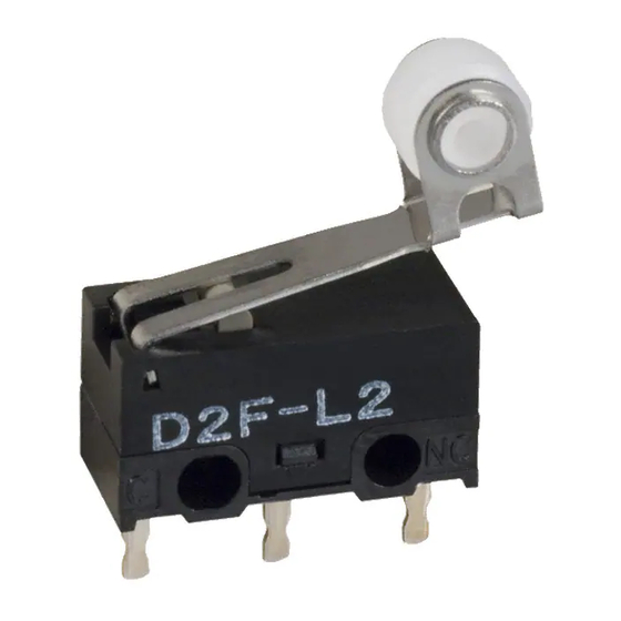
Ultra Subminiature Basic Switch
Subminiature Size Ideal for PCB
Mounting (12.8 6.5 5.8 (W H D))
Incorporating a snapping mechanism made with
two highly precise split springs that ensures a long
service life.
Insertion molded terminals and a two-stage bottom
with different levels prevent flux penetration.
Self-clinching PCB, right-angled, left-angled, and
solder terminals are available.
Meets a wide range of applications, including home
appliances, audio equipment, office machines, and
communications equipment.
Ordering Information
Model Number Legend
D2F-jjjj
1
2
3
4
1.
Ratings
None: General loads
01:
Micro loads (0.1 A at 30 VDC)
2.
Maximum Operating Force
None: 1.47 N {150 gf}
F:
0.74 N {75 gf}
Note: These values are for the pin plunger models.
3.
Actuator
None: Pin plunger
L:
Hinge lever
L2:
Hinge roller lever
L3:
Simulated roller lever
4.
Terminals
None: PCB terminals/straight terminals
-T:
Self-clinching PCB terminals
-A:
Right-angled PCB terminals
-A1:
Left-angled PCB terminals
-D3:
Solder terminals
-D:
Compact solder terminals
D2F
RC
197
Advertisement
Table of Contents

Related Manuals for Omron D2F


Summary of Contents for Omron D2F
- Page 1 Meets a wide range of applications, including home appliances, audio equipment, office machines, and communications equipment. Ordering Information Model Number Legend D2F-jjjj Ratings Terminals None: General loads None: PCB terminals/straight terminals Micro loads (0.1 A at 30 VDC)
-
Page 2: List Of Models
125 VAC 30 VDC 0.5 A 0.1 A Note: 1. Consult your OMRON sales representative before using the Switch with inductive or motor loads. 2. The ratings values apply under the following test conditions: Ambient temperature: 20±2°C Ambient humidity: 65±5%... - Page 3 3. For the pin plunger models, the values are at the free position and total travel position. For the lever models, they are at the total travel position. 4. For testing conditions, consult your OMRON sales representative. Approved Standards Contact Form...
- Page 4 Operating frequency: 30 operations/min 3,000 125 VAC 1,000 30 VDC OT (mm) Switching current (A) For details about the D2F-01, consult your OMRON sales representative. Dimensions Note: All units are in millimeters unless otherwise indicated. Terminals PCB Terminals (Standard) Self-clinching PCB Terminals 1.6±0.15...
-
Page 5: Mounting Holes
2. Unless otherwise specified, a tolerance of ±0.4 mm applies to all dimensions. 3. The following illustrations and drawings are for D2F models with PCB terminals. Self-clinching, solder, and right-angled, left-angled terminals are omitted from the following drawings. Refer to page 200 for these terminals. When ordering, replace j with the code for the terminal that you need. - Page 6 D2F-01 Use M2 mounting screws with plane washers or spring washers to securely mount the Switch. Tighten the screws to a torque of 0.08 to 0.1 N•m {0.8 to 1 kgf•cm}.
- Page 7 General Information General Information Correct Use Electrical Conditions Area Item Page Load Using Switches The switching capacity of a switch significantly differs depending on Selecting Correct Switch whether the switch is used to break an alternating current or a direct Electrical Load current.
-
Page 8: General Information
General Information General Information Contact Protective Circuit Apply a contact protective circuit (surge killer) to extend contact du- When a switch is used under high humidity, arcs resulting from cer- rability, prevent noise, and suppress the generation of carbide or ni- tain types of load (e.g., inductive loads) will generate nitrious oxides tric acid due to arc. -
Page 9: Mechanical Conditions
General Information General Information Mechanical Conditions Switching Speed and Frequency The switching frequency and speed of a switch have a great influ- Operating Stroke Setting ence on the performance of the switch. Pay attention to the follow- The setting of stroke is very important for a switch to operate with ing. -
Page 10: Terminal Connections
General Information General Information • Incorrect Do not modify the actuator. If the actuator is modified, excessive external force may be applied to the internal switch mechanism, Snap-back characteristics may change, and the switch may stop Shock operation functioning. • If an external actuator is used as an operating object, check the material and thickness of the lever to make sure that the force applied to the lever is within the permissible range. - Page 11 General Information General Information terminals, otherwise the terminal may be deformed or the housing Operation and Storage Environment may be damaged. Handling Wiring Work Do not apply oil, grease, or other lubricants to the sliding parts of a When wiring a switch, check the insulation distance between the switch.
- Page 12 General Information General Information Switch Trouble and Corrective Action Type Location Failure Possible cause Corrective action of failure Failures Contact Contact Dust and dirt on the contacts. Remove the cause of the problem, place related to l t d t f il failure the switch in a box, or use a sealed...
Need help?
Do you have a question about the D2F and is the answer not in the manual?
Questions and answers