Table of Contents
Advertisement
Quick Links
Service Manual
Laser beam safety precaution .......................................... 1
Tape adjustments ............................................................ 1
Tuner adjustments ........................................................... 2
CD pick-up maintenance .................................................. 2
Exploded view .................................................................. 3
(Cabinet & Chassis) ...................................................... 4
(Tape mechanism) ........................................................ 7
(CD mechanism) ........................................................... 8
IC block diagram & description ........................................ 9
FL display description ...................................................... 15
This service manual consists of
"DC-MM5000U/AU" (Main unit : 129 651 06) &" SX-MM5000/UK" (Speaker system : 165 066 01).
All manuals and user guides at all-guides.com
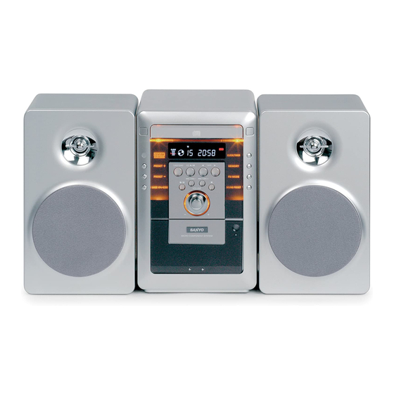
Micro Component System
FILE NO.
DC-MM5000
PRODUCT CODE No.
129 652 06
Wiring connection ............................................................ 16
(CD) ............................................................................... 18
(FRONT) ....................................................................... 20
(AMPLIFIER ) ................................................................ 24
(TUNER) ....................................................................... 26
(CD) ............................................................................... 17
(FRONT) ....................................................................... 22
(AMPLIFIER & TUNER) ................................................ 28
(POWER SUPPLY) ....................................................... 30
(KEYBOARD) ................................................................ 30
REFERENCE No.
(AU)
SM
5810421
Advertisement
Table of Contents

Related Manuals for Sanyo DC-MM5000


Summary of Contents for Sanyo DC-MM5000
-
Page 1: Table Of Contents
All manuals and user guides at all-guides.com FILE NO. Service Manual DC-MM5000 Micro Component System (AU) PRODUCT CODE No. 129 652 06 Laser beam safety precaution .......... 1 Wiring connection ............16 Tape adjustments ............1 Schematic diagram Tuner adjustments ............2 (CD) ................ -
Page 2: Laser Beam Safety Precaution
All manuals and user guides at all-guides.com LASER BEAM SAFETY PRECAUTION • Pick-up that emits a laser beam is used in this CD player section. CAUTION : THIS PRODUCT CONTAINS A LOW POWER LASER DEVICE, TO ENSURE CONTINUED SAFETY DO NOT REMOVE ANY COVERS OR ATTEMPT TO GAIN ACCESS TO THE INSIDE OF THE PRODUCT. -
Page 3: Tuner Adjustments
Clean a lens with swab of the cotton which moistened it with alcohol, cleaning paper or cleaning disc appointed. Specified cleaning disc : LC-1 (Part code : 645 026 1961 ..manufactured by SANYO.) Show a clean procedure in the following in reference by swab of cotton. -
Page 4: Exploded View
All manuals and user guides at all-guides.com EXPLODED VIEW (CABINET & CHASSIS) - 3 -... -
Page 5: Parts List (Cabinet & Chassis)
All manuals and user guides at all-guides.com PARTS LIST PRODUCT SAFETY NOTICE EACH PRECAUTION IN THIS MANUAL SHOULD BE FOLLOWED DURING SERVICING. COMPONENTS IDENTIFIED WITH THE IEC SYMBOL IN THE PARTS LIST AND THE SCHEMATIC DIAGRAM DESIGNATED COMPONENTS IN WHICH SAFETY AND ! ! ! PERFORMANCE CAN BE OF SPECIAL SIGNIFICANCE. - Page 6 All manuals and user guides at all-guides.com PARTS LIST KEYBOARD P.W.BOARD ASSY REF.NO. PART NO. DESCRIPTION Q6304 405 143 0007 TR KRC107M REF.NO. PART NO. DESCRIPTION 405 000 3806 TR DTC114YS 614 325 3617 ASSY,PWB,KEYBOARD(Only Initial) S6001 645 057 4689 SWITCH,ROTARY(ENCODER) CN650 614 326 6174 ASSY,WIRE,KEYBOARD-FRONT S6110...
- Page 7 All manuals and user guides at all-guides.com PARTS LIST REF.NO. PART NO. DESCRIPTION REF.NO. PART NO. DESCRIPTION D2151 407 012 4406 DIODE 1SS133 Q4502 405 000 3806 TR DTC114YS D2153 407 105 1602 VARACTOR DI SVC342M-V 405 143 0007 TR KRC107M 407 105 1305 VARACTOR DI SVC342L-V Q4600 405 155 0002 TR MPSA56...
-
Page 8: Exploded View & Parts List(Tape Mechanism)
All manuals and user guides at all-guides.com PARTS LIST CD P.W.BOARD ASSY REF.NO. PART NO. DESCRIPTION Q1301 405 008 7301 TR 2SB810-F REF.NO. PART NO. DESCRIPTION 405 008 7202 TR 2SB810-E 614 325 2047 ASSY,PWB,CD(Only Initial) 405 008 6809 TR 2SB808-F-SPA CN111 645 059 0498 SOCKET,FPC 16P Q1401... -
Page 9: Cd Mechanism
All manuals and user guides at all-guides.com EXPLODED VIEW & PARTS LIST(CD MECHANISM) CM14 CM01 CM03 CM02 CM04 CM15 CM05 CM15 CM16 CM06 CM16 CM17 CM07 CM18 CM19 CM20 CM12 CM13 CM11 CM09 CM08 CM10 CD MECHANISM MECHA SWITCH P.W.BOARD ASSY REF.NO. -
Page 10: Ic Block Diagram & Description
All manuals and user guides at all-guides.com IC BLOCK DIAGRAM & DESCRIPTION IC101 LA9242M-MPB (Servo Processing Signal for a CD Player) Vcc1 BH1 PH1 VR REF1 Vcc2 DRF CE DAT CL CLK 54 53 RF DET FIN2 FIN1 DGND INTER FACE RFS- RF Amp RFSM... - Page 11 All manuals and user guides at all-guides.com IC BLOCK DIAGRAM & DESCRIPTION IC103 MM1469XH (CD Driver) D.BUF D.BUF D.BUF D.BUF DRIVER MUTE T.S.D D.BUF D.BUF D.BUF D.BUF Pin No. Symbol Description Pin No. Symbol Description ch1 OUT-A Driver ch1 negative output OP IN(-) Operational amplifier input, negative ch1 OUT-B Driver ch1 positive output...
- Page 12 All manuals and user guides at all-guides.com IC BLOCK DIAGRAM & DESCRIPTION IC231 LA1844ML (Electronic Tuning-supported Home Audio Tuner IC) RF.AMP PILOT DECODER BUFF CANCEL ANTI-BIRDIE P-DET STEREO LEVEL AM/FM COMP S-CURVE BUFF PILOT 304kHz TUNING DRIVE IC241 LC72121M-D (PLL Synthesizer) Vssx REFERENCE PHASE DETECTOR...
- Page 13 All manuals and user guides at all-guides.com IC BLOCK DIAGRAM & DESCRIPTION IC440 AN7348K (PLAY/REC Pre Amp) A/Rec Mute PB Amp(L) Nor/Cro Amp(L) & Hi/Lo Logic PB Amp(R) Amp(R) A/Rec Mute Ripple Logic Rejection Logic Rec/PB IC441 LC75342M (2 Band Equalizer) LSELO LIN LTRE LBASS1 LBASS2 LOUT...
- Page 14 All manuals and user guides at all-guides.com IC BLOCK DIAGRAM & DESCRIPTION IC601 LC866540A-51D1 (Micro Processor) Interrupt Control Standby Control X’tal BaseTimer BusInterface SIO0 Port 1 B Register SIO1 Port 3 C Register Timer 0 Port 7 Timer 1 Port 8 INT0 to 3 Noise Filtter SI0 Automatic...
- Page 15 All manuals and user guides at all-guides.com IC BLOCK DIAGRAM & DESCRIPTION IC601 LC866540A-51D1 (Micro Processor) PIN NAME NAME DESCRIPTION PIN NAME NAME DESCRIPTION FL drive output power P16/BUZ JOG+ Input JogDial S20/PC4 O FL Segment output (P13) P17/PWM0 JOG- Input JogDial S21/PC5 O FL Segment output (P12)
-
Page 16: Fl Display Description
All manuals and user guides at all-guides.com FL DISPLAY DESCRIPTION FL601 PIN No. CONNECTION 9G 10G PIN No. CONNECTION P10 P11 P12 P13 P14 P15 P16 P17 *NOTES* 1) F1,F2 : Filament 3) Pn : Anode Pin 5) NX : No Extended 2) G : Grid PIn 4) NP : No Pin... -
Page 17: Wiring Connection
All manuals and user guides at all-guides.com WIRING CONNECTION CN111 (16P) CN122 (12P) CD P.W.B CN123 (5P) AM LOOP ANT. CN113 (6P) CN114 (5P) CN202 ANT. CN445 (10P) CN480 (5P) CN440 (6P) VIDEO (AUDIO) CN400 SPINDLE/SLED (28P) CN450 MOTOR AND CN455 LIMIT SWITCH AMPLIFIER &... -
Page 18: Wiring Diagram (Cd)
All manuals and user guides at all-guides.com WIRING DIAGRAM (CD) CN114 C1373 J1306 J1303 J1304 LIMIT J1506 J1405 Q1401 J1406 PR101 J1407 IC103 J1501 J1502 J1503 PR132 C1403 J1510 C1408 C1404 C1404 C1404 C1881 D1403 C1339 D1402 C1773 C1783 R1881 R1881 R1881 DGND... -
Page 19: Schematic Diagram (Cd)
All manuals and user guides at all-guides.com SCHEMATIC DIAGRAM (CD) R1461 DSP_RESET R1462 CQCK R1463 COIN R1475 SQOUT VREF Q1301 VREF 2SB810 R1465 PICK UP C1335 R1453 DT11T3CN 22;50 2.7K C1491 0.01 COMMON IC101 C1302 1000P LA9242M R1340 EFLG DEFI FIN2 100;16 R1342... - Page 20 All manuals and user guides at all-guides.com SCHEMATIC DIAGRAM (FRONT) D6010 L6010 1SS133 R6009 C6118 100P C6010 1000/6.3 C6117 100P C6116 100P FL601 S6001 C6111 100P 100 99 98 97 96 95 94 93 92 91 90 89 88 87 86 85 84 83 82 81 C6110 100P MOTOR...
-
Page 21: (Front)
All manuals and user guides at all-guides.com WIRING DIAGRAM ( FRONT) D6321 D6320 R6322 R6321 S6001 C6010 R6323 R6324 J6226 C6212 L6010 J6214 R6113 J6225 R6111 R6111 R6111 Q6108 C6213 C6213 C6213 C6111 C6111 C6111 C6112 C6112 C6112 J6325 C6110 C6110 C6110 R6145... -
Page 22: (Amplifier )
All manuals and user guides at all-guides.com SCHEMATIC DIAGRAM (AMPLIFIER) R4820 R4703 R4821 8.2K CD_R L4581 R4822 4.7K TDA7265 22UH TU_R IC442 C4703 R4823 L4891 1500P AUX_R BEAD R4881 L4881 L4781 R4825 220K L-OUT 22UH 22UH Q4700 KRC107 R4781 R4922 L4791 R-OUT BEAD... -
Page 23: (Tuner)
All manuals and user guides at all-guides.com SCHEMATIC DIAGRAM (TUNER) C2106 1000P R2204 XF211 IC211 XF222 XF233 LA1186N T2002 C2114 R2201 R2306 XF221 Q2201 C2306 1;50 KTC3195 2.7K XF231 C2322 R2205 1000P C2305 0.47;50 C2321 1;50 R2202 C2105 R2105 C2111 0.01 R2301 1.5K... - Page 24 All manuals and user guides at all-guides.com WIRING DIAGRAM (AMPLIFER & TUNER) CN456 CN457 S4901 CN202 CN450 CN480 CN455 J4602 XF211 C4992 C4821 J4718 R4851 C4850 C4750 R4751 CT252 C4851 R4850 R4750 C4751 C4722 J4728 L2102 R4829 R4823 R4723 R4729 R4729 R4729 C4996...
- Page 25 All manuals and user guides at all-guides.com WIRING DIAGRAM (POWER SUPPLY & KEYBOARD) POWER SUPPLY P.W.BOARD 1AD4B10D1670B NOTE: T002 94V-0 TW ONLY L4191 FU421 T4A L 250V J4211 C4283 C4283 C4283 D4283 C4281 C4281 C4281 D4281 C4280 C4280 C4280 D4280 C4282 C4282 C4282...
- Page 26 All manuals and user guides at all-guides.com SANYO Electric Co., Ltd. Osaka, Japan May. / '03 Printed in Japan...