Advertisement
Quick Links
CIRCUIT
DIAGRAM
REVISION 0
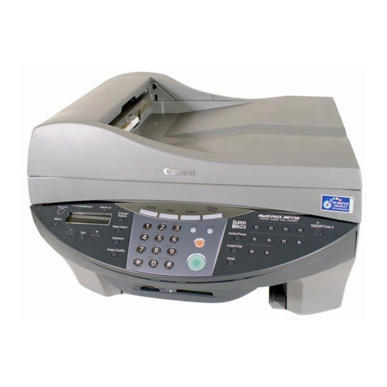
SmartBase MP730
SmartBase MP730
SmartBase MP730
SmartBase MP730
SmartBase MP700
SmartBase MP700
SmartBase MP700
MAR. 2003
COPYRIGHT © 2003 CANON INC.
HY8-80AU-000
CANON SmartBase MP730/MP700 MAR. 2003
H12-2693 230V EU
H12-2694 230V UK
H12-2695 230V GER
H12-2697 230V FRN
H12-2703 230V EU
H12-2704 230V UK
H12-2705 230V E/G/F
Advertisement

Summary of Contents for Canon Smart Base MP730
- Page 1 H12-2694 230V UK SmartBase MP730 H12-2695 230V GER SmartBase MP730 H12-2697 230V FRN SmartBase MP700 H12-2703 230V EU SmartBase MP700 H12-2704 230V UK SmartBase MP700 H12-2705 230V E/G/F HY8-80AU-000 MAR. 2003 COPYRIGHT © 2003 CANON INC. CANON SmartBase MP730/MP700 MAR. 2003...
- Page 2 When changes occur in applicable products or in the content of this manual, Canon will release technical information as the need arises. In the event of major changes in the contents of this manual, Canon will issue a new editions of this manual.
- Page 3 I. ABOUT THIS MANUAL This manual is divided into the following four sections and contains information necessary for servicing the products. 1. HOW TO USE THE CIRCUIT DIAGRAM This section describes how to read and use this manual correctly. 2. CIRCUIT DIAGRAM This section contains information necessary for servicing the products, and includes the circuit diagrams of the products.
- Page 4 II. PRODUCT NO. LIST This manual describes the component units of the following products. DRAWING No. PRODUCT No. H12-2693 H12-2703 H12-2694 H12-2704 UNIT NAME H12-2695 H12-2705 H12-2697 SPCNT BOARD ASS’Y HM1-0498 HM1-0510 HM1-0599 SENSOR BOARD ASS’Y HM1-0499 HM1-0464 HM1-0465 HM1-0503 MODULAR BOARD ASS’Y HM1-0501 HM1-0501...
- Page 5 III. CONTENTS PAGE TITLE DRAWING No. 1. HOW TO USE THE CIRCUIT DIAGRAM 1.1 Symbol 1.2 Index 1.3 Signal Address List 1.4 Power Supply Parts Rating List 2. CIRCUIT DIAGRAM SPCNT BOARD ASS'Y SPCNT BOARD ASS'Y HM1-0498-A501 SPCNT BOARD ASS'Y HM1-0498-A502 SPCNT BOARD ASS'Y HM1-0498-A503...
- Page 6 4. POWER SUPPLY PARTS RATING LIST POWER SUPPLY PARTS RATING LIST HK1-0049...
- Page 7 1. HOW TO USE THE CIRCUIT DIAGRAM 1.1 Symbol The symbols used in this circuit diagram conform to Canon standards. However, the circuit diagram of the power supply unit, etc. which are manufactured by other companies, use the standard symbols of those other manufacturers.
- Page 8 c) JUMPER TERMINAL SYMBOL Jumper terminal symbols are as shown below. Connected Jumper Terminal Disconnected Jumper Terminal Figure 3 Jumper Terminal Symbol d) UNMOUNTED PART SYMBOL Parts marked with ### are not mounted on the PCB. SW330 is not mounted on the PCB. # # # JP328 <F.
- Page 9 1.3 SIGNAL ADDRESS LIST The following is an example of how to read the signal address list. Drawing number of the signal address list on this page. e.g. To see the circuit diagram of drawing number HG1-3923, refer to the signal address lists beginning with drawing number HG1-3923-AA01 Row number on the signal address list.
- Page 10 1.4 POWER SUPPLY PARTS RATING LIST The following is an example of how to read the power supply parts rating list. Drawing number of the power supply parts rating list on this page. e.g. To see the circuit diagram of drawing number HH3-5244, refer to the power supply parts rating list of drawing number HH3-5244.
- Page 48 0303IP CANON INC.
- Page 49 CIRCUIT CIRCUIT DIA- DIA- GRAM GRAM CIRCUIT CIRCUIT DIA- DIA- GRAM GRAM CIRCUIT CIRCUIT DIA- DIA- GRAM GRAM CIRCUIT CIRCUIT DIA- DIA- GRAM GRAM CIRCUIT CIRCUIT DIA- DIA- GRAM GRAM CIRCUIT CIRCUIT DIA- DIA- GRAM GRAM CIRCUIT CIRCUIT DIA- DIA- GRAM GRAM CIRCUIT...


