Table of Contents
Advertisement
Quick Links
Advertisement
Table of Contents

Related Manuals for ECOWITT HP1000SE PRO


Summary of Contents for ECOWITT HP1000SE PRO
-
Page 1: Table Of Contents
HP1000SE PRO Ultrasonic WiFi Internet Funk Wetterstation Manual (EN) -
Page 2: Table Of Contents
1 Table of Contents 1 Table of Contents ..................1 2 Unpacking ....................4 3 Overview ..................... 6 3.1 Display Console ................... 6 3.2 Indoor sensor ..................7 3.3 Ultrasonic anemometer with 6-in-1 sensors ......... 8 3.4 Rain Sensor ..................8 3.5 Features .................... - Page 3 4.8.4 Optional Sensor Display Mode ........... 39 4.9 Setting Mode ..................40 4.9.1 Date and Time setting ..............42 4.9.2 Time Format setting ..............43 4.9.3 Date Format setting ..............44 4.9.4 Temperature unit setting ............. 44 4.9.5 Barometric unit ................44 4.9.6 Wind speed unit ................
-
Page 4: Unpacking
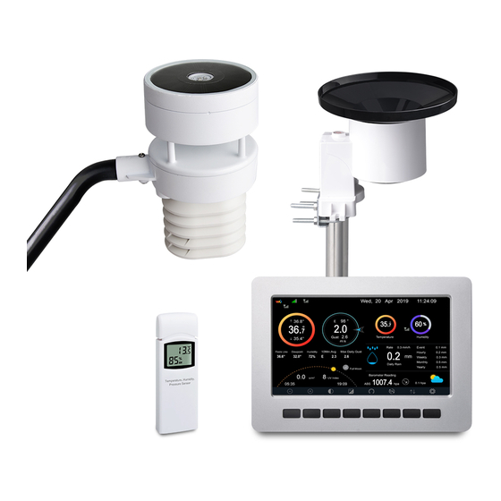
2 Unpacking Open your weather station box and inspect that the contents are intact (nothing broken) and complete (nothing missing). Inside you should find the following: Item Description Display Console Indoor sensor unit(temp/humidity/pressure) Solar powered ultrasonic anemometer with Light and UV, air temperature/humidity sensor integrated( optional heater for climate with snow/ice conditions available) Rain gauge... - Page 5 card. The supported max capacity of the card is 32G(Format: FAT32). A 1GB card will store more than 10 years’ data. There is also no requirement on the speed class of this card as data writing happens infrequently and is not speed critical.
-
Page 6: Overview
3 Overview 3.1 Display Console Figure 1: Display console screen Figure 2 Display console side views Note: The USB port in the console is only for factory internal use, not internal use, not available for users. -
Page 7: Indoor Sensor
You can use a microSD card for the firmware update.( microSD card not included). Update firmware process: visit www.froggit.de for available update, copy “user.bin” file onto microSD card main root. Insert SD card while display in operation, it will immediately show an update process, follow the instruction to complete update. -
Page 8: Ultrasonic Anemometer With 6-In-1 Sensors
3.3 Ultrasonic anemometer with 6-in-1 sensors Figure 4: Solar powered ultrasonic anemometer with integrated solar & uv, thermo-hygrometer sensor 3.4 Rain Sensor Figure 5: Self emptying rain gauge... -
Page 9: Features
https://www.wow.com Custom own server data hosting possible when server data exchange is compatible with either Wunderground or Ecowitt protocol. Manage sensor calibration setup. Manage sensor via sensor ID. Data storage service on Ecowitt server: https://ecowitt.net... - Page 10 The optional DP50, DP60, DP70, DP100, DP200 can be Note: purchased separately. Make sure to select the model of the units with the same RF frequency as your gateway (the frequency is different for various countries because of regulations). Note: There’s a built-in heat plate in the 6-in-1 sensor package body, if the lowest temperature at your place is below -3°C, or 26.6°F, and the weather is mostly snowy or rainy, then you may need to activate the heater by supplying an external 5V/1A power to the sensor heating element for...
-
Page 11: Set Up Guide
4 Set up Guide Before you start, you will need a screwdriver (size PH0, not provided) and find the wrench (size M5) included in package. We suggest you assemble all components of the weather station, including Note: base unit in one location so you can easily test functionality. After testing, place the outdoor sensors in the desired location. -
Page 12: Ultrasonic Anemometer Package Assembly
Anemometer Ideally mounted at least 32 feet, or 10 meters above ground level. Try to make the anemometer the highest object around. 7 feet, or 2.75 meters) or more above the surrounding obstructions is best. Rain Gauge Ideally mounted at a height of 4 to 6 feet, or 1.5 to 2 meters above the ... -
Page 13: Install Batteries In Sensor Package
1. Surface tension conditioner layer 7. Mounting arm ( patent pending) 2. Battery compartment 8. Mounting bracelet and U-bolt set 3. Temperature & humidity sensor 9. Power cord for built-in heater 4. Light & UV sensor, LED indicator 10. USB port (factory use only ) 5. -
Page 14: Mount Ultrasonic Anemometer Assembly
Please make sure the battery is inserted correctly for its polarity as Note: the system needs its initial power from this backup battery to start up the system before solar panel charges up the accumulator and supply system power afterwards. when in high altitude area,during wintertime, sunshine time is short, thus system needs to be powered from this backup battery, we recommend Lithium batteries to be used for cold weather climates. - Page 15 Figure 8: Sensor package mounting diagram 5-1 2. Pass the connector cord through the arm tube as Figure 9: If you don’t need to power up the heater, we suggest you tie up the power cord and keep in th tube. This can make the installation looks neat and tidy.
- Page 16 Figure 9: Sensor package mounting diagram 5-2 3. Attaching the arm tube to the Ultrasonic Sensor as Figure 10. Figure 10: Sensor package mounting diagram 5-3 4. Insert the arm tube into the base as Figure 11. Be sure to line up the small hole in the arm with the holes in the base.
- Page 17 Figure 11: Sensor package mounting diagram 5-4 Make sure the mounting pole is vertical, or very close to it. Use a level as needed. 5. If optional extension cord is added, connect the cord to the connector and insert the USB port into the AC adaptor as Figure 10 show: Figure 12: Sensor package mounting diagram 5-5...
-
Page 18: Reset Button And Transmitter Led
Finally, place the sensor package on top of the prepared mounting pipe. The U-Bolts should be loose enough to allow this but loosen the nuts as necessary. Once placed, hand tighten all four nuts, taking care to do so evenly. Do not use a wrench yet! Now you will need to align the whole package in the proper direction by rotating it on top of the mounting pipe as needed. -
Page 19: Rain Gauge Sensor Set Up And Installation
4.3 Rain Gauge Sensor Set Up and Installation See Figure 13 to locate and understand all the parts of the rain gauge sensor once fully assembled. Figure 13: Sensor assembly components Rain collector funnel Battery compartment door LED Indicator Surface installation screw hole Bubble level U-bolt installation hole Table 3: Sensor assembly detailed items... -
Page 20: Install Rain Collector Top
Take out the filter hook from the edge to uninstall. Take out the filter hook from the edge to uninstall. Hook the filter hook on the edge to install. Figure 14: Rain gauge filter in/un-installation diagram installation diagram 4.3.2 Install rain collector top Align the rain collector top with the rain bucket, pay attention to the lock pay attention to the lock groove position as shown on the left side in Figure 15. -
Page 21: Install Batteries In Rain Gauge Sensor
4.3.3 Install Batteries in rain gauge sensor Remove the battery door on the back of the sensor by sliding it in the direction of the arrow. Insert one AA battery as described and put compartment door back and slide it in the opposite direction to lock. Make sure battery door is firmly press and closed properly, which is extremely important in preventing any water entering inside. - Page 22 adjustments easier and avoids any distance or interference related issues from the setup. After setup is complete and everything is working, return here for outdoor mounting. If issues show up after outdoor mounting they are almost certainly related to distance, obstacles etc. Mounting with U-bolts 4.3.4.2 The mounting assembly includes two U-Bolts and a bracket that tightens...
-
Page 23: Indoor Sensor Set Up
Mounting with screws 4.3.4.3 The mounting assembly also includes two screws for installation on a flat surface. Figure 18: Rain gauge sensor mounting with screws installation diagram Use the bubble level beside the rain sensor as a guide to verify that the Note: sensor is leveled. -
Page 24: Sensor Placement
Figure 4: Indoor sensor battery installation 4.4.1 Sensor Placement The best mounting location for the indoor sensor is in a location that never receives direct sunlight, not even through windows. Also, do not install in a location where a nearby radiant heat source (radiator, heaters, etc.) will affect it. -
Page 25: Best Practices For Wireless Communication
Figure 20: Indoor sensor mounting Make sure the sensor is mounted vertically and not lying down on a flat Note: surface. This will insure optimum reception. Wireless signals are impacted by distance, interference (other weather stations, wireless phones, wireless routers, TVs and computer monitors), and transmission barriers, such as walls. - Page 26 receivers to avoid the interference and establish reliable communication. The frequencies used by the sensors are one of (depending on your location): 433, 868, or 915 MHz (915 MHz for United States). Line of Sight Rating. This device is rated at 300 feet line of sight ...
-
Page 27: Console Display
4.6 Console Display See Figure to help you identify elements of the console’s display screen. to help you identify elements of the console’s display screen. Figure 21: Display Console Screen Layout... - Page 28 Description Description Outdoor temperature Last lightning strikes detected time / distance; daily counts (optional DP60 sensor) Outdoor Feels Like/Dew Indoor humidity point/Humidity/10Min. Average Wind Direction/Max Daily Gust PM2.5 concentration(optional RF signal bar for multi-channel DP200 sensor) temperature and humidity sensor(optional sensor) RF signal bar for PM2.5 Multi-channel temperature and sensor(optional DP200 sensor)
-
Page 29: Initial Display Console Set Up
4.6.1 Initial Display Console Set Up Immediately after power up (inserting power adapter), the unit will turn on Immediately after power up (inserting power adapter), the unit will turn on the display, and the unit will start to look for reception of the indoor and the display, and the unit will start to look for reception of the indoor and outdoor sensor data. -
Page 30: Key Functions
Note: Sunrise/sunset time display will only work properly when GEO location has been set up correctly. GEO setup can be carried out under setup menu. 4.6.2 Key functions Figure: Buttons around the display There is a set of eight keys on the bottom of the display console. The following tables briefly explains the function of these keys. -
Page 31: Main Interface Icons Explain
times to enter optional Multi-channel Sensors Display Mode channel Sensors Display Mode Setting key Press this key to enter Setting Mode Table: Console buttons 4.6.3 Main interface icons explain Temperature Icon 4.6.3.1 Temperature Range Color Temperature Range Temperature Range Color (degF) Ring (degF) - Page 32 Humidity Icon 4.6.3.2 Humidity Range (%) Color Humidity Range Humidity Range Color Ring Ring 0%, No signal or 50 to 60 50 to 60 dashes 1 to 10 60 to 70 60 to 70 10 to 20 70 to 80 70 to 80 20 to 30 80 to 90...
-
Page 33: Multiple Channel Selection And Scroll Mode
50 to 60 Current wind direction indication , 10-minute average minute average 4.6.3.3 wind direction indication Hourly Rainfall Icon 4.6.3.4 Hourly Rain (in) Icon Hourly Rain (in) Color Ring 0.6 to 0.8 0 to 0.2 0.8 to 1 0.2 to 0.4 1 to 1.2 0.4 to 0.6 1.2 to 1.4... -
Page 34: History Mode
While in Scroll display mode, the scroll icon will be displayed next to the indoor humidity, and will scroll every 5 seconds. Note: For all optional sensor(s), the history data will be saved to a microSD card(not included). 4.8 History Mode 4.8.1 View and Reset MAX/MIN While in normal display, press the key once to view and reset... -
Page 35: History Record Mode
Selection key Press this key to select the weather MAX/MIN record which need to clear Enter key While the desired weather MAX/MIN record selected , press this key to popup Message Box ”Clear the Max/Min record?”. Press key or key to select YES or NO. Press the key or key to confirm the selection. - Page 36 Figure : History record Screen Icon Description File Select key Press this key to clear all history record Page Select key Press this key to enter particular page of the history data. Each Press this key to enter particular page of the history data. Each page contains 16sets data.
- Page 37 While in History Record Mode, press key to popup the popup the Message Box: “Clear the history record?” Press “Yes” to clear all history records saved on “Clear the history record?” Press “Yes” to clear all history records saved on console.
-
Page 38: Graph Mode
Figure : view a specific page of history Screen view a specific page of history Screen Press to select a digit in a number, press to change the number. Press to change the activated option change the activated option field, toggle OK or Cancel then press key to confirm. -
Page 39: Optional Sensor Display Mode
Press to shift the data display of 12/24/48/72H. Press to view the graph of the following data: Indoor outdoor humidity Dew Point and Feels like Indoor outdoor temperature Wind speed and Gust Wind Direction Solar radiation Rainfall hourly and daily Barometer(REL &... -
Page 40: Setting Mode
While in Graph Mode, press the key once to enter Optional Sensor Optional Sensor Display Mode. 4.9 Setting Mode While in normal display, press the key to enter Setting Mode. You can key to enter Setting Mode. You can select the below sub-mode by pressing the... - Page 41 Figure : Setup Menu Screen Icon Description Select key Press this key to select the unit or scrolls the value Select key Press this key to select the unit or scrolls the value. scrolls the value. Left key Press this key to select the set value. Right key Press this key to select the set value.
-
Page 42: Date And Time Setting
4.9.1 Date and Time setting While in Menu Setting Mode, press key to select Date and Time key to select Date and Time Setup field, press key to enter Date and Time Setup mode: key to enter Date and Time Setup mode: Figure : Time and date Setup Screen Time setting (hour/minute/second) Press... -
Page 43: Time Format Setting
Press key to select Date setting field, the day digit on focus turns red, press the key to change the day setting. Press to set the month, then month digit focused will turn red, press the to change the month setting. Press to set the year, the year digit on focus will turn red, press the key to change the year setting... -
Page 44: Date Format Setting
4.9.3 Date Format setting Press to change the time format between DD-MM–YYYY, YYYY-MM- DD and MM-DD-YYYY 4.9.4 Temperature unit setting Press to change the temperature units of measure between °F and °C. 4.9.5 Barometric unit Press to change the temperature units of measure between inHg, mmHg and hPa 4.9.6 Wind speed unit Press... - Page 45 Figure : Multi channel sensor Setup Screen Figure : Multi channel sensor Setup Screen Press key to select Name setting field, the name on focus key to select Name setting field, the name on focus turns green, press the key to pop up the keyboard to enter the key to pop up the keyboard to enter the sensor name.
- Page 46 Figure : rename the sensor Screen Press key to select Register setting field, press the key to select Register setting field, press the key to register the selected sensor...
-
Page 47: Backlight Setting
4.9.10 Backlight setting While in Menu Setting Mode, press key to select Backlight Setup field, key to select Backlight Setup field, press key to enter backlight Setup mode: Figure : Backlight Setting Screen Automatic control backlight: select this option, the backlight will auto turn Automatic control backlight: select this option, the backlight will auto turn on and off according the set time Turn on the backlight: set the time of turning on backlight... -
Page 48: Longitude: Latitude Setting
Icon Description Select key Press this key to select the unit or scrolls the value Select key Press this key to select the unit or scrolls the value. Left key Press this key to select the set value. Right key Press this key to select the set value. -
Page 49: Barometric Display
Figure : Longitude and Latitude Setting Screen Figure : Longitude and Latitude Setting Screen The sunrise/sunset times will be calculating automatically base on the The sunrise/sunset times will be calculating automatically base on the Longitude and Latitude. Your location GEO info can be found on mobile Latitude. -
Page 50: Storing Interval (1-240Minutes Selectable)
Ecowitt Weather Site: https://www.ecowitt.net Ecowitt’s new weather server that can host a bunch of sensors that other services don’t support at this time. Table: Supported weather services If you are testing the setup with the outdoor sensor package nearby... - Page 51 final outdoor installation, come back and change the password after clearing final outdoor installation, come back and change the password after clearing console history. That will start uploading to the services with a clean slate. rt uploading to the services with a clean slate. Press key to enter Weather Server set up mode.
- Page 52 1) Set Station ID. Press to highlight the Station ID. Enter your to highlight the Station ID. Enter your station ID. Press to display the keyboard. Press to display the keyboard. Press to scroll to the character and press to select the character.
- Page 53 Registering with and using wunderground.com Registering with and using wunderground.com 4.9.15.1 Perform the following steps to get the Station ID and Password get the Station ID and Password on wunderground.com: Visit Wunderground.com and select the Join link (1) at the top of the link (1) at the top of the page and select the Free (2) sign up option.
- Page 54 Select More | Register Your PWS (5) again. This time you will be (5) again. This time you will be asked details about your weather station. Go ahead and fill out the form asked details about your weather station. Go ahead and fill out the form After completing the weather station, you will see something like this: r station, you will see something like this: Your station ID will have the form: KSSCCCC###, where K is for USA...
- Page 55 Figure 31: Weather Server setup screen : Weather Server setup screen scroll value scroll value Scroll field Scroll field return to down down Setup...
- Page 56 1) Set Station ID. Press to highlight the Station ID. Enter your station ID. Press to display the keyboard. Press to scroll to the character and press to select the character. Press to return to the setup page. 2) Set Station Key. Press to highlight the station key.
- Page 57 There are also some very useful mobile apps. The URLs provided here go to the Web version of the application pages. You can also find them directly from the iOS or Google Play stores: WunderStation: iPad application for viewing your station’s data and ...
- Page 58 WU Storm: iPad and iPhone application for viewing radar images, ad and iPhone application for viewing radar images, animated wind, cloud coverage and detailed forecast, and PWS station animated wind, cloud coverage and detailed forecast, and PWS station data https://itunes.apple.com/us/app/wu-storm/id955957721 Weather Underground: Forecast: iOS and Android application for : iOS and Android application for...
- Page 59 PWS Weather Station Monitor: View weather conditions in your : View weather conditions in your neighborhood, or even right in your own backyard. Connects to right in your own backyard. Connects to wunderground.com https://itunes.apple.com/us/app/pws-weather-station-monitor/id7137059 monitor/id7137059...
- Page 60 Note: If you want to share your station data with other users, you’ll need to set your data to be public. Other users need to log in the ecowitt.net first to view your data. It will show a page such as this, where you can look at today’s data and...
- Page 61 Dashboard Graph display...
- Page 62 List display Weather Map...
- Page 63 Email Alerts Customized server setup 4.9.15.5 For highly experienced users, it offers the option to send data to the user highly experienced users, it offers the option to send data to the user’s own server. Press the “setup” button to enter Customized setup screen, setup screen, Figure : Server setup screen...
- Page 64 Select Enable button and select the protocol type. The website he website should has the same protocol with Wunderground or Ecowitt. Input all the information needed. nput all the information needed.
-
Page 65: Connect Console To Your Router: Wi-Fi Scan
4.9.16 Connect Console to Your Router: Wi-Fi scan Entering this mode, system will display all the available Wi Entering this mode, system will display all the available Wi-Fi networks. Select the SSID that you want console to be connected with SSID that you want console to be connected with (only supports 2.4GHz band Wi-Fi network ) , and enter passer word as required. - Page 66 If the Wi-Fi network you would like to connect is with a hidden SSID, please follow below steps to connect: 1) Press to select Hidden SSID setup, and press directly to enter. 2).Press to highlight the SSID. Press to display the keyboard and enter your SSID.
-
Page 67: Background
4.9.17 Background While in Menu Setting Mode, press key to select Background Setup key to select Background Setup field, press key to choose between dark background display key to choose between dark background display and light background display... -
Page 68: Alarm Setting Mode
4.9.18 Alarm Setting Mode Icon Description Select key Press this key to select the unit or scrolls the value Select key Press this key to select the unit or scrolls the value. Left key Press this key to select the set value. Right key Press this key to select the set value. -
Page 69: Calibration Mode
alarm will sound for 120 second and the corresponding icon will flash alarm will sound for 120 second and the corresponding icon will flash until the weather condition doesn’t meet the user set level. Press any until the weather condition doesn’t meet the user set level. Press any key to mute the alarm. - Page 70 To adjust the parameter, press to scroll to the parameter you wish to change. Press to highlight the sign (positive vs. negative, if applicable) and significant digit. Press to change the calibrated value. Parameter Type of Default Typical Calibration Source Calibration Temperature Offset...
- Page 71 other weather stations) are not a good source and have their own margin of error. Using a local weather station in your area is also a poor source due to changes in location, timing (airport weather stations are only updated once per hour) and possible calibration errors (many official weather stations are not properly installed and calibrated).
- Page 72 The standard sea-level pressure is 29.92 in Hg (1013 mb). This is the average sea-level pressure around the world. Relative pressure measurements greater than 29.92 inHg (1013 mb) are considered high pressure and relative pressure measurements less than 29.92 inHg are considered low pressure. To determine the relative pressure for your location, locate an official reporting station near you (the internet is the best source for real time barometer conditions, such as Weather.com or...
-
Page 73: More
Without a calibrated source, wind speed can be difficult to measure. We recommend using a calibrated wind meter (not included) and a constant speed, high speed fan. (7) The rain collector is calibrated at the factory based on the funnel diameter. - Page 75 Note: To calibrate the optional soil moisture sensor, please refer to the manual of refer to the manual of the DP100 soil moisture senor. To calibrate the PM2.5 sensor, you’ll need to find a reliable source, such as ll need to find a reliable source, such as professional devices from your local air quality service.
-
Page 77: Factory Reset
4.9.21 Factory reset Re-register indoor transmitter 4.9.21.1 Press key to select re-register indoor transmitter. Press register indoor transmitter. Press key to popup the Message Box ”Register a new indoor ”Register a new indoor... - Page 78 transmitter?” Press to select Yes or No. Press the key to confirm the selection. Re-register outdoor transmitter 4.9.21.2 Please reference section 5.13.1. Procedures and settings are similar to re- register indoor transmitter. Automatic Clear Max/Min 4.9.21.3 To turn on/off automatically clear Max/Min record at 0:00hr every day. Press key to select Automatic clear Max/Min.
- Page 79 select Yes or No. Press the key to confirm the selection. Clear Max/Min 4.9.21.6 Press key to select Clear Max/Min. Press to popup the Message Box ”Clear the max/min record?” Press to select Yes or No. Press the key to confirm the selection. Backup data 4.9.21.7 Press...
- Page 80 About information 4.9.21.8 Note: This figure is just for reference(model and frequency will change according to different market). The actual display console may be with higher firmware version than this manual described because we will update the firmware occasionally. Language 4.9.21.9 Press key to select Language.
-
Page 81: Other Console Functions
5 Other Console Functions 5.1 Beaufort Wind Force Scale If you have selected the use of Beaufort wind speed units, you can use the table below for reference. The Beaufort scale is based on qualitative wind conditions and how they would affect a ship’s (frigate) sails (so yes, it is an “old”... -
Page 82: Weather Forecasting
5.2 Weather Forecasting The five weather icons are Sunny, Partly Cloudy, Cloudy, Rainy and Stormy. The forecast icon is based on the rate of change of barometric pressure. Please allow at least one month for the weather station to learn the barometric pressure over time. -
Page 83: Weather Forecasting Description And Limitations
5.4 Weather Forecasting Description and Limitations Weather Forecasting Description and Limitations In general, if the rate of change of pressure increases, the weather is In general, if the rate of change of pressure increases, the weather is generally improving (sunny to partly cloudy). If the rate of change of y cloudy). - Page 84 Day 3 Day 16 Day 4 Day 17 Day 5 Day 18 Day 6 Day 19 Day 7 Day 20 Day 8 Day 21 Day 9 Day 22 Day 10 Day 23 Day 11 Day 24 Day 12 Day 25 Day 13 Day 26 Full Moon...
-
Page 85: Maintenance
6 Maintenance The following steps should be taken for proper maintenance of your station Clean Rain Gauge Check the rain gauge every 3 months. Rotate the funnel counterclockwise and lift it up. Clean the funnel and bucket with a damp cloth to remove any dirt, debris and insects. - Page 86 Clean solar radiation sensor and solar panel The solar radiation sensor and solar panel of the outdoor sensor array need to be cleaned with a non-abrasive slightly damp cloth every 3 months. Replacing batteries regularly Batteries of the outdoor sensor array should be replaced every 1-2 years. In applications where data dropouts cannot be tolerated, check the batteries every 3 months and apply a corrosion preventing compound (not included) on the battery terminals for protection.
-
Page 87: Troubleshooting Guide
7 Troubleshooting Guide Look through the following table and locate an issue or problem you are experiencing in the left column and read possible solutions in the right column. Problem Solution Wireless remote (thermo- The maximum line of sight communication range hygrometer) not reporting is about 600’. - Page 88 Problem Solution Bring the sensor array inside the house (you can disconnect it from the rest of the sensors). The LED next to the battery compartment will flash according reporting time specifications. If the LED is not flashing as that… Replace the batteries in the sensor.
- Page 89 Problem Solution have a stable, level mounting solution. Data not reporting to 1. Confirm your password is correct. It is the Wunderground.com password registered Wunderground.com. Your Wunderground.com password cannot begin with a non-alphanumeric character (a limitation of Wundeground.com, not the station). Example, $oewkrf is not a valid password, but oewkrf$ is valid.
-
Page 90: Specifications
8 Specifications Out of range values will be displayed using “---” Note: Outdoor sensor Specification Transmission distance 100m open field RF Frequency 868 MHz Temperature range -40°C – 60°C (-40°F - 140°F) Temperature accuracy ± 1°C, or ± 2°F Temperature resolution 0.1°C, or 0.1°F Humidity range 10% ~ 99%... - Page 91 When the maximum wind speed of the last 4s is >=5m/s, the wind speed is detected by 1s; when the maximum wind speed of the last 4s is >=3m/s and less than 5m/s, the wind speed is detected by 2s; when the maximum wind speed of the last 4s is <3m/ s, the wind speed is detected by 4s.
- Page 92 Note: The primary power source for the outdoor sensor is the solar panel. When available solar power (light over recent period) is insufficient, the batteries will be used. In outdoor climates that frequently have sustained temperatures below 0°C (or 32°F) the use of Lithium batteries is strongly suggested as these are performing better than Alkaline batteries under such circumstances.
- Page 93 Gerneral safety insructions Danger of asphyxiation: Keep all packaging materials (plastic bags, rubber bands, etc.) away from children. There is a danger of suffocation! Danger of burns: Caution! Leaking / leaking battery acid can lead to burns! Avoid contact of battery acid with eyes, mucous membranes and skin.
- Page 94 Notes on the return of batteries according to §12 BatterieVO: Batteries do not belong in the household waste. Please dispose of all batteries as required by law, disposal in domestic waste is expressly prohibited. Batteries and rechargeable batteries can be dispensed free of charge at municipal collection points or in the shops on the spot. This manual may not be reproduced in any form without the written permission of the publisher, even in excerpts.
- Page 95 HS Group GmbH & Co. KG Escherstr.31 50733 Koeln Germany Telefon 0221 / 367 48 05 E-Mail info@hs-group.de Registergericht Amtsgericht Koeln HRA 26493 Komplementaer: HS Group Verwaltungsgesellschaft mbH Sitz Koeln Registergericht Amtsgericht Koeln HRB 64734 Geschaeftsfuehrer: Peter Haefele, Carl Schulte UStId DE237971721 WEEE Reg.
Need help?
Do you have a question about the HP1000SE PRO and is the answer not in the manual?
Questions and answers