Table of Contents

Related Manuals for IET Labs DE-5000


Summary of Contents for IET Labs DE-5000
- Page 1 ♦ ♦ PRECISION INSTRUMENTS FOR TEST AND MEASUREMENT DE-5000 Portable, Full-Featured LCR Meter User and Service Manual IET LABS, INC. www.ietlabs.com 534 Main Street, Westbury, NY 11590 TEL: (516) 334-5959 • (800) 899-8438 • FAX: (516) 334-5988...
- Page 2 ♦ ♦ ♦ ♦ PRECISION INSTRUMENTS FOR TEST AND MEASUREMENT PRECISION INSTRUMENTS FOR TEST AND MEASUREMENT IET LABS, INC. IET LABS, INC. www.ietlabs.com www.ietlabs.com 534 Main Street, Westbury, NY 11590 534 Main Street, Westbury, NY 11590 TEL: (516) 334-5959 • (800) 899-8438 • FAX: (516) 334-5988...
- Page 3 PRECISION INSTRUMENTS FOR TEST AND MEASUREMENT DE-5000 Portable, Full-Featured LCR Meter User and Service Manual Copyright © 2011 IET Labs, Inc. Visit www.ietlabs.com for manual revision updates DE-5000 im/October 2011 IET LABS, INC. www.ietlabs.com 534 Main Street, Westbury, NY 11590...
- Page 4 ♦ ♦ PRECISION INSTRUMENTS FOR TEST AND MEASUREMENT IET LABS, INC. www.ietlabs.com 534 Main Street, Westbury, NY 11590 TEL: (516) 334-5959 • (800) 899-8438 • FAX: (516) 334-5988...
- Page 5 WARRANTY We warrant that this product is free from defects in material and workmanship and, when properly used, will perform in accordance with applicable IET specifi cations. If within one year after original shipment, it is found not to meet this standard, it will be repaired or, at the option of IET, replaced at no charge when returned to IET.
- Page 6 WARNING OBSERVE ALL SAFETY RULES WHEN WORKING WITH HIGH VOLTAGES OR LINE VOLTAGES. Dangerous voltages may be present inside this instrument. Do not open the case Refer servicing to qualifi ed personnel HIGH VOLTAGES MAY BE PRESENT AT THE TERMINALS OF THIS INSTRUMENT WHENEVER HAZARDOUS VOLTAGES (>...
-
Page 7: Table Of Contents
Table of Contents Chapter 1: Introduction ............1 1.1. Overview ................1 1.2. Introduction to measuring principles ........2 1.2.1. What is impedance ............2 1.2.2. Measuring impedance ............4 1.3. Equivalent circuit ...............6 1.4. Instrument layout ..............7 1.5. LCD display layout ............10 Chapter 2: Operation ............ - Page 8 2.7. Additional features ............33 2.7.1. Connecting to a PC ............33 2.7.2. Using the backlight ............35 2.7.3. Holding a reading on the display ........35 2.8. Replacing Batteries ............36 Chapter 3: Specifications ............37 3.1. General specifications ............37 3.2.
-
Page 9: Chapter 1: Introduction
IR-USB interface. It also features a Sorting mode, allowing users to quickly sort components. DE-5000 has automatic LCR selection. This allows the user to measure the L/C/R components in Auto LCR mode without having to select the type of measurement. -
Page 10: Introduction To Measuring Principles
To accommodate various test requirements, the DE-5000 offers selectable test frequencies: 100 Hz / 120 Hz / 1 kHz / 10 kHz / 100 kHz. The unit is powered by a standard 9V battery. For additional convenience, it may also use an optional ac adapter (DE-5000-AC). - Page 11 Zs = Rs + jXs or |Zs| ∠Θ Rs = |Zs| cosΘ Xs = |Zs| sinΘ Xs/Rs = tanΘ Θ = tan (Xs/Rs) There are two types of reactance. One is inductive reactance – , and the other is capacitive reactance – X If Θ...
-
Page 12: Measuring Impedance
1.2.2. Measuring impedance Impedance can be measured in series or in parallel. In parallel mode, impedance can be represented as reciprocal of admittance (Y). The admittance can be defined as Y = G + jB, where: G = Conductance B = Susceptance Series impedance Parallel admittance Y = 1/Z = 1/Rp + 1/jXp = G+jB... - Page 13 Both Rs and Rp are part of the equivalent circuit of capacitors and inductors. When measuring capacitance and inductance, it is best to use the settings as shown in the table below. Value Setting Parallel Capacitance High Series Series Inductance High Parallel - 5 -...
-
Page 14: Equivalent Circuit
1.3. Equivalent circuit - 6 -... -
Page 15: Instrument Layout
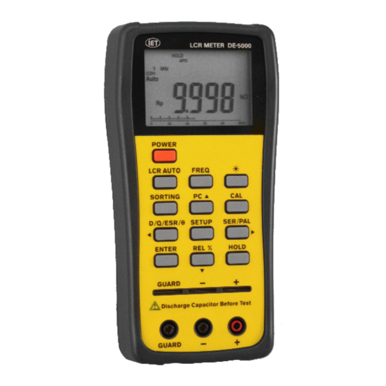
1.4. Instrument layout Front panel Side GUARD provides a shield to reduce noise for device under test (DUT), test leads, and other equipment. - 7 -... - Page 16 21. TL-21 Alligator –lead test-lead adapter (4-wire joined at alligator clips) 22. TL-22 SMD tweezers, 4-wire (optional) Rear 23. TL-23 Guard Line IR- USB interface (optional) - 8 -...
- Page 17 LCD display POWER Turns the instrument on/off. LCR auto mode, Inductance, Capacitance, Resistance and DC LCR AUTO resistance measurement selection FREQ Testing frequency selection Backlight display SORTING Sorting mode control PC ▲ UART output control Open/Short calibration mode D/Q/ESR/Θ D/Q/ ESR/Θ parameters selection Setup menu control SETUP (in sorting mode )
-
Page 18: Lcd Display Layout
1.5. LCD display layout Sorting Sorting function is enabled Tolerance indicator in sorting mode : ±0.25%, ±0.5%, ± 1%, ±2%, ±5%, ±10%, ±20%, & +80%-20% Testing frequency indicator: 1kHz,10kHz,100kHz,100Hz & 120Hz PC connection is active Battery capacity indicator Range selection is enabled on setup menu of Range sorting mode Auto... - Page 19 Dissipation factor, Quality factor or Phase angle is Θ D/Q/ active for L/C measurement mode ac Resistance in parallel mode is active Open/Short calibration mode HOLD Data Hold Auto power off mode Series equivalent resistance mode Secondary Display ° Phase angle Unit for Resistance ( , k and M ) –...
-
Page 20: Chapter 2: Operation
Chapter 2: Operation 2.1. How to obtain optimum precision To access optimum precision for all L, C, and R measurements, especially at the highest and the lowest ranges, zero the instrument before use (pages 16-18). To secure the specified accuracy, connect the device under test (DUT) to the measuring socket, or use either TL-21 (standard accessory) or TL-22 (optional accessory). - Page 21 When the meter is powered by the battery, it is in an automatic-power-off mode. APO is shown on the display. In this mode, if the unit is inactive for 5 minutes, it shuts itself off. First, the buzzer beeps three times to remind the user, then OFF is displayed on the monitor as shown below while the unit powers down.
-
Page 22: Zeroing The Meter
2.3. Zeroing the meter Zeroing the instrument gets better accuracy for impedance measurements. The purpose of this procedure is to reduce the parasitic effect of the test fixture. is the total impedance measured on the device under test (DUT) by a test fixture which has some parasitic impedance. = (Rs + jωLs) + ((Go+jωCo)-1 || Z is the target impedance user wants to measure. - Page 23 To zero the meter, proceed as follows: 1. Make sure the leads are completely disconnected. 2. Press the CAL key for 2 seconds. OPEn The monitor should display as shown below. 3. Pres the CAL key again. The unit should begin a countdown as it performs OPEN calibration.
- Page 24 4. Connect the test leads for form a short circuit. 5. Press the CAL key again. The monitor should display Srt as shown below. 6. Press the CAL key one more time. The unit should begin a countdown as it performs SHORT calibration.
-
Page 25: Attaching Dut's To The Meter
2.4. Attaching DUT’s to the meter Devices under test (DUT’s) may be connected to the meter as follows: • Insert DIP component leads to the sockets directly. • Attach Alligator-clip test-lead adapter (TL-21) 4-Wire Alligator Test Lead Case Guard line (TL- 23) provides (TL-21) a shield for DUT, preventing interference when measuring... - Page 26 • Attach SMD tweezers (TL-22, optional). Guard line (TL-23) provides a shield for DUT, preventing interference when measuring high-impedance components 4-wire SMD Tweezers (TL-22) - 18 -...
-
Page 27: Primary Measurements And Functions
2.5. Primary measurements and functions 2.5.1. Measuring inductance, capacitance, and resistance The DE-5000 starts out in Auto LCR mode which can detect the type of impedance and measure it automatically – either inductance (L), capacitance (C), or resistance (R). Dc resistance (DCR) can only be selected manually. - Page 28 Impedance can also be selected manually by pressing the LCR AUTO key. This is what the process would look like: The meter starts out in Auto LCR mode. Press LCR AUTO key. The meter enters Auto L mode. The secondary parameter is Q. Press LCR AUTO key.
- Page 29 The meter enters Auto R mode. The secondary parameter is blank. (The meter only displays Θ automatically in Auto LCR mode.) Press LCR AUTO key. The meter enters DCR mode. The secondary parameter is blank. Press LCR AUTO key. The meter returns to Auto LCR mode.
-
Page 30: Measuring Dissipation, Quality, Esr, And Phase Angle
2.5.2. Measuring dissipation, quality, ESR, and phase angle The DE-5000 can measure dissipation factor (D), quality factor (Q), equivalent series resistance (ESR), and phase angle (Θ). These readings are shown in the secondary display. To select the appropriate measurement, cycle through the options using the D/Q/ESR/Θ... - Page 31 The secondary display shows D/Q/ESR/Θ Press key. The secondary display Θ shows D/Q/ESR/Θ Press key. The secondary display returns to - 23 -...
-
Page 32: Sorting Components
2.5.3. Sorting components The DE-5000 can sort components into PASS/FAIL categories. Components may be sorted based on resistance, capacitance, or inductance. Note: this function is not available in Auto LCR mode. Before using this function, set the meter to either Auto L mode, Auto C mode, or Auto R mode. - Page 33 5. To adjust the nominal value, proceed as follows: a. Use ◄ / ► keys to adjust the position of the decimal point as necessary. Press ENTER when finished. b. Use ◄ / ► / ▲ / ▼ keys to adjust the Press ENTER digits as necessary.
-
Page 34: Making Relative Measurements
SETUP and repeat steps 5 and 6 above. To exit the Sorting mode, press SORTING. 2.5.4. Making relative measurements The DE-5000 meter can make relative measurements. This option is controlled by the REL% key. When the Relative mode is active, the display shows the ∆ symbol. - Page 35 To access the Relative mode proceed as follows: 1. Zero the meter. See pages 14-16 for details. 2. Select the parameter to be tested. L, C, R, or DCR 3. Attach the chosen standard to the test points. 4. Press the REL% key. ∆...
- Page 36 Example: In Capacitance mode Display shows the measurement reading. Ex. 669.3 nF REL% Press ∆ appears on the screen The reading on the display is stored as reference value. 0.0% is shown on the secondary display since the measured value reference are the same at this point.
- Page 37 The new reading is shown on the primary display. The % difference is shown on the secondary display. REL% Press key again ∆ flashes on the screen, and the reference value shows on primary display. - 29 -...
-
Page 38: Additional Settings
2.6. Additional settings 2.6.1. Selecting test frequency The DE-5000 meter can test at the following frequencies: 100 Hz, 120 Hz, 1 kHz, 10 kHz, and 100 kHz. The default frequency setting is 1 kHz. To cycle through the available frequencies, pres the FREQ key. - Page 39 The test frequency is now 100Hz. FREQ Press key. The test frequency is now 120Hz. FREQ Press key. test frequency returns to 1 kHz. Note: test frequency affects the accuracy of the reading. See accuracy charts on pages 35-36. The LCR impedance scale ranges are based on the test frequency.
-
Page 40: Making Measurements In Series And Parallel
2.6.2. Making measurements in series and parallel The DE-5000 meter can make measurements in series or parallel. To select the appropriate option, press the SER/PAL key. Note: this function is available in Auto L, Auto C, and Auto R modes only. In other modes the SER/PAL key is disabled. -
Page 41: Additional Features
PC for remote operation and data storage. If you have the optional Data Transfer Kit (DE-5000-DTK), you may connect to a PC as follows: Snap on IR-USB adapter and connect to a PC via a USB cable. - Page 42 PC communication is active. PC appears on the display. PC ▲ Press key. disappears from the display, and the PC communication is inactive. - 34 -...
-
Page 43: Using The Backlight
2.7.2. Using the backlight To use the back light, press key. To turn it off, press key again. Note that the backlight is disabled automatically after the meter is inactive for 60 seconds. 2.7.3. Holding a reading on the display Normally, the reading of any given DUT disappears as soon as the device is disconnected from the test points. -
Page 44: Replacing Batteries
2.8. Replacing Batteries The DE-5000 is powered by a single, standard, 9 V, alkaline battery. When the battery is at full power, the display shows . When the battery power is running out, the display shows Caution: To maintain the meter within... -
Page 45: Chapter 3: Specifications
Chapter 3: Specifications 3.1. General specifications Parameters measured: Ls / Lp / Cs / Cp / Rs / Rp / DCR with D/Q/Θ/ESR measurement Automatic L-C-R selection Selectable test model: Series or Parallel Display: Backlit 20,000/2,000 count Input connection: 4-Wire spring-loaded sockets and biding post jacks Accepts normal or shrouded banana plugs Automated LCR ranges: L: 20.000 µH -- 2000 H... - Page 46 Response time: Approx. 1 second/DUT Available tolerances for sorting function: ±0.25% ±5% ±0.5% ±10% ±1% ±20% ±2% -20/+80% Temperature coefficient: [0.15 x (specified accuracy)]/°C 0-18°C, 28-50°C Test signal level: 0.5 Vrms Typical Environmental: Operating temperature: 0°C to 50°C; <70% RH Storage temperature: -20°C to 60°C;...
-
Page 47: Accuracy Specifications
3.2. Accuracy specifications Accuracy is specified at 23°C ± 5°C, <75% RH. All accuracy is specified as ±[(% of reading) + (value of least significant digit)]. For most precise measurements, the meter has to be zeroed first. Resistance: Range Resolution 100/120Hz 1kHz 10kHz... - Page 48 Inductance: Range Resolution 100/120Hz 1kHz 10kHz 100kHz 20.000 µH 0.001 µH ─ ─ ─ 2.5%+5 200.00 µH 0.01 µH ─ ─ 1.2%+5 0.6%+3 2000.0 µH 0.1 µH ─ 2.0%+5 0.6%+3 0.6%+3 20.000 mH 0.001 mH 1.2%+5 1.0%+5 0.3%+2 0.6%+3 200.00 mH 0.01 mH 0.3%+2 0.6%+3...
- Page 49 Adjustment to accuracy (Z) based on dissipation (D) reading: D > 0.1: Z * √(1+D In capacitance mode, D ≤ 0.1: Z = 1÷(2πƒC) In inductance mode, D ≤ 0.1: Z = 2πƒL Secondary Parameters Accuracy: = impedance (Z) accuracy Definition: Q = 1/D &...
-
Page 50: Ordering Information
3.3. Ordering information DE-5000 Standard Package: LCR meter DE-5000-LCR Carrying case DE-5000-CS Alligator-clip test-lead adapter TL-21 (4-wire joined at the alligator clips) Guard lead TL-23 DE-5000-9V Standard 9 V battery Instruction manual DE-5000-IM Optional Accessories: AC adapter DE-5000-AC SMD tweezers (4-wire) - Page 51 ♦ ♦ PRECISION INSTRUMENTS FOR TEST AND MEASUREMENT IET LABS, INC. www.ietlabs.com 534 Main Street, Westbury, NY 11590 TEL: (516) 334-5959 • (800) 899-8438 • FAX: (516) 334-5988...
- Page 52 ♦ ♦ PRECISION INSTRUMENTS FOR TEST AND MEASUREMENT IET LABS, INC. www.ietlabs.com 534 Main Street, Westbury, NY 11590 TEL: (516) 334-5959 • (800) 899-8438 • FAX: (516) 334-5988...
Need help?
Do you have a question about the DE-5000 and is the answer not in the manual?
Questions and answers