Table of Contents
Advertisement
Advertisement
Table of Contents

Related Manuals for Pride Amp Series


Summary of Contents for Pride Amp Series
- Page 1 PRIDE DX-300 Service Manual Amp Series Copyright © 2004 CBTricks.com Version. 1.0...
- Page 2 Be sure to stop by the CBTricks web site and check it out. http://www.cbtricks.com/ A WORD OF THANKS TO THE FOLLOWING PEOPLE FOR HELPING WITH THIS MANUAL. Chris Reifsteck (Nomad Radio) , Joe Piatt, and N-Channel. Safety Instructions READ FIRST BEFORE SERVICING THIS AMPLIFIER Lethally high voltages are present inside the amplifier unit.
-
Page 3: Table Of Contents
Pride DX-300 INDEX PAGE CHAPTER 1 Introduction Introduction: ..............1 Specifications: . - Page 4 Pride DX-300 INDEX Circuit Modifications CHAPTER 7 Introduction: ..............31 Screen LED Modification: .
-
Page 5: Chapter 1 Introduction
The products that Pride built where assembled by handicap people hence the slogan printed on the back of the amplifier “Manufactured with Pride by the Handicap”. I think that most of the DX300’s where built between 1977 and 1978. Some people say that Pride was in the business of selling CB amplifiers under the guise of amateur radio amps. -
Page 6: Chapter 2 Operation
Pride DX-300 CHAPTER 2 2.0 INSTALLATION: 1) Select a location for your amplifier. RF amplifiers need ventilation, so choose a location that will not restrict the air flow around the amp and where it won’t get water, coffee, or soft drinks spilled on or in it. -
Page 7: Operation
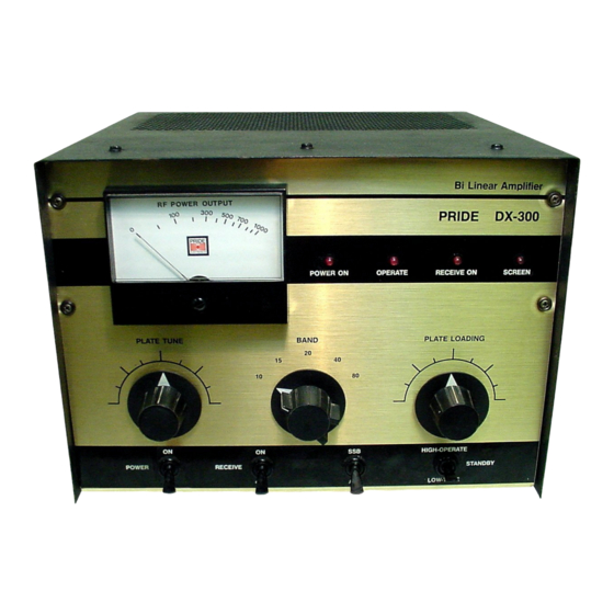
Pride DX-300 CHAPTER 2 Figure 2-1 Front Panel 2.1 OPERATION: 1) Check to see that the TUNE/STANDBY/OPERATE switch is in the center or STANDBY position. Apply power to the unit by switching the POWER switch to the ON position. You will hear the cooling blower come up to speed. - Page 8 Pride DX-300 CHAPTER 2 9) For SSB operation, drive power should now be gradually increased to 10 or 12 watts, and the unit peaked for maximum output. This can be done using the carrier insertion control on some exciters, or if this is not available, a steady tone may be applied to the microphone input.
-
Page 9: Chapter 3 Circuit Description
Pride DX300 CHAPTER 3 3.0 Circuit Description: The DX-300 power amplifier uses a 4CX-250B Tetrode ceramic/metal construction, and utilizes forced air- cooling. It is in a grounded cathode, driven grid configuration that provides very high power gain, high peak power output, and excellent linearity and harmonic suppression. The use of tuned input circuits and broadband matching transformers permits low drive operation combined with additional rejection of exciter harmonics. -
Page 10: Screen And Bias Supplies
Pride DX300 CHAPTER 3 3.2 Screen and Bias Supplies PCB: The screen and bias supply is also bridge rectified, but with a center tapped transformer and filter string that allows a split output voltage. Approximately 700 VDC is developed across the two 40µf filter caps (C33, C34), but due to the circuit configuration this shows up as +350 and -350 VDC. -
Page 11: Input And Control
Pride DX300 CHAPTER 3 3.4 R.F. Input and Control Board: This board is located under chassis near the tube socket, and is mounted horizontally. It contains the R.F. switching circuitry, input matching transformer and tuned toroid input coils, the receiver preamp, and some of the control circuitry. - Page 12 Pride DX300 CHAPTER 3 Another set of contacts on the (RL1) 4PDT relay switches the cathode circuit of the tube to ground when the amplifier goes into the "on the air" condition. When not transmitting, two 18K, 2W resistors (R46, R47) provide a cathode blocking bias that prevents the tube from pulling current.
-
Page 13: Safety Interlock
Pride DX300 CHAPTER 3 3.5 Safety Interlock PCB Figure 3-5 Safety Interlock Circuit Never turn on the amp with cover off: The shorting safety switch will cause the high voltage to short out. If this happens it will usually takes out R59 or the bridge rectifier. -
Page 14: Plate Current Measurement
The following information is presented so that the competent service technician should have no trouble in performing routine service on the Pride DX-300. Lethally high voltages are present inside the amplifier unit. Never remove either top or bottom cover when power line is connected. -
Page 15: Bias Voltage Adjustment
Pride DX300 CHAPTER 4 4.1 Bias voltage adjustment: The following adjustment is from the factory manual you may want to do it another way. The bias voltage should rarely need attention. If, however, the tube is changed or the adjustment is otherwise disturbed, the following procedure should be adhered to. -
Page 16: Wattmeter Calibration
Pride DX300 CHAPTER 4 4.2 Wattmeter Calibration: The following adjustment is from the factory manual you may want to do it bypassing the safety interlock and adjust it with the top removed but use caution. If adjustment becomes necessary, it should be performed only if the following equipment is available: Exciter: 100 to 200watts output at 28 MHz Dummy load: 50ohm with an accurately calibrated wattmeter. -
Page 17: Voltage Checks
Pride DX300 CHAPTER 4 4.4 Voltage Checks As the voltages present on the DX-300 chassis are potentially lethal, the procedure below must be followed when checking voltages. 1) Make sure that the unit is unplugged and has been off for several minutes to allow all voltages to bleed to zero. -
Page 18: Tube Replacement
Pride DX300 CHAPTER 4 4.6 Tube Replacement: If a tube failure does occur, a likely reason for this would be a loss of one or more of the required operating voltages at the tube socket. Thus, before a tube is replaced, the voltage measurement procedure should be followed to determine if further repairs are necessary. -
Page 19: Low Voltage Supply Pcb
Pride DX300 CHAPTER 5 5.0 Low Voltage Supply PCB: Copyright © 2004 CBTricks.com... -
Page 20: High Voltage Supply Pcb (Board #1)
Pride DX300 CHAPTER 5 5.1 High Voltage Supply PCB (Board #1): Copyright © 2004 CBTricks.com... -
Page 21: High Voltage Supply Pcb (Board #2)
Pride DX300 CHAPTER 5 5.2 High Voltage Supply PCB (Board #2): Copyright © 2004 CBTricks.com... -
Page 22: Wattmeter Pcb
Pride DX300 CHAPTER 5 5.3 Wattmeter PCB: Copyright © 2004 CBTricks.com... -
Page 23: Rf Input And Control Pcb
Pride DX300 CHAPTER 5 5.4 RF Input and Control PCB: Copyright © 2004 CBTricks.com... -
Page 24: Safety Interlock Pcb
Pride DX300 CHAPTER 5 5.5 Safety Interlock PCB: Copyright © 2004 CBTricks.com... -
Page 25: Pcb Trace Layouts
Pride DX300 CHAPTER 5 5.6 PCB Trace Layouts: Copyright © 2004 CBTricks.com... -
Page 26: Pcb Trace Layouts (Cont.)
Pride DX300 CHAPTER 5 PCB Trace Layouts (Cont.): Copyright © 2004 CBTricks.com... -
Page 27: Chassis Layouts Front And Rear
Pride DX300 CHAPTER 5 5.7 Chassis Layouts Front and Rear: Copyright © 2004 CBTricks.com... -
Page 28: Chassis Layouts Top And Bottom
Pride DX300 CHAPTER 5 5.8 Chassis Layouts Top and Bottom: Copyright © 2004 CBTricks.com... -
Page 29: High Voltage Power Supply Pcb #1
Pride DX300 CHAPTER 6 6.1 HIGH VOLTAGE PWR SUPPLY #1: Ref. # Description MFR. Part No. ASSY DX-300 HIGH VOLTAGE PWR SUPPLY #1 01-0300-01 PCB DX-300 HIGH VOLTAGE PWR SUPPLY 82-0300-01 Resistors Ref. # Description MFR. Part No. Resistor, Carbon Film 470K Ohm 1/2W... -
Page 30: High Voltage Power Supply Pcb #2
Pride DX300 CHAPTER 6 6.2 HIGH VOLTAGE PWR SUPPLY #2: Ref. # Description MFR. Part No. ASSY.HIGH VOLTAGE PWR SUPPLY #2 01-0300-00 HIGH VOLTAGE PWR SUPPLY PCB 82-0300-01 Resistors Ref. # Description MFR. Part No. Resistor, Carbon Film 470K Ohm 1/2W... -
Page 31: Low Voltage Power Supply Pcb
Pride DX300 CHAPTER 6 6.4 LOW VOLTAGE PWR SUPPLY: Ref. # Description MFR. Part No. ASSY. LOW VOLTAGE PWR SUPPLY 01-0300-02 LOW VOLTAGE PWR SUPPLY PCB 82-0300-02 Resistors Ref. # Description MFR. Part No. Resistor, Carbon Film 470K Ohm 1/2W... -
Page 32: Rf Input And Control Pcb
Pride DX300 CHAPTER 6 6.5 RF INPUT AND CONTROL BOARD: Ref. # Description MFR. Part No. ASSY. RF INPUT AND CONTROL 01-0300-03 RF INPUT AND CONTROL PCB 82-0300-03 Inductors Ref. # Description MFR. Part No. Choke, SUB MIN 200µH NIN Q47 80 METERS 24-2000-00 ASSY. -
Page 33: Wattmeter Pcb
Pride DX300 CHAPTER 6 6.6 WATTMETER PCB: Ref. # Description MFR. Part No. ASSY. WATTMETER PCB 01-0300-09 WATTMETER PCB 82-0300-06 Inductors Ref. # Description MFR. Part No. ASSY. Toroid Coil 17 Winding 01-0300-27 Resistors Ref. # Description MFR. Part No. -
Page 34: Chassis (Cont.)
Pride DX300 CHAPTER 6 CHASSIS (Cont.) Ref. # Description MFR. Part No. ASSY. Tank Coil 15-80 Meters 01-0300-15 Choke, RF 1mH 160 MA 24-1006-00 Capacitor Strap 85-0300-17 Ref. # Description MFR. Part No. Dial, Figure Black DX-300 32-0299-00 Knob, Black DX-300... -
Page 35: Chapter 7 Circuit Modifications
7.2 Screen Supply Modification The Pride DX300 has no screen regulation and should, Nomad Radio (http://www.nomadradio.com) is working on a new Low Voltage PCB. I have seen Prides with a 25K 10W to ground on the +350v supply. A person could build a regulator for the supply. So check his web site for details. -
Page 36: Bias Circuit Modification Version 1
Pride DX300 CHAPTER 7 7.5 Bias Circuit Modification Version1 (Nomad Radio Mod) The Bias voltage is a Negative 82 Volt supply which is set between -65 and -68 volts to the tube. The most common part failure is the bias pot (RV1) 500ohm 2W linear pot and an 82-Volt 5-Watt zener (D25). -
Page 37: Introduction
Pride DX300 CHAPTER 8 8.0 Introduction: In this section I have information on some of the components use in the DX300. 8.1 Antenna Change Over and Preamp Relay Information: The antenna change over relay (RL1) is a 4- pole double throw (4PDT) relay with 10 amp contacts and a 12 volt 185ohm coil. - Page 38 Copyright © 2004 CBTricks.com...
-
Page 39: Blower Detail
Pride DX300 CHAPTER 8 8.6 Blower Detail: HOWARD INDUSTRIES PART NUMBER FOR THE BLOWER: 3-20-1250 I think this translates to "3-inch wheel", 20 CFM at 1250 rpm. RF Parts has this Blower #87-1250 for $39.95 8.7 Repair Part Suppliers RF Parts Company WESTGATE LABORATORIES L.L.C. - Page 40 Nomad Radio Heavy-Duty High-Voltage power-supply board kit for the Pride DX-300 base amplifier. The Kit includes all the parts to build a single PCB HV Power Supply that replaces both HV PCB in a Pride DX300. This PCB lets you completely remove the original two H.V. circuit boards and install the single-piece replacement.
Need help?
Do you have a question about the Amp Series and is the answer not in the manual?
Questions and answers