Table of Contents

Related Manuals for Hornady LOCK-N-LOAD


Summary of Contents for Hornady LOCK-N-LOAD
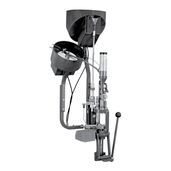
- Page 1 PLANT • Auto Progressive (AP ) Reloading Press ™ • Powder Measure & Case Activated Powder Drop • Case Feeder • Pistol Bullet Feeder Instructional and troubleshooting videos for this product are available on the Hornady website. Item No. 095160...
- Page 2 Items included with your Lock-N-Load Ammo Plant ® See pages 4-5 See pages 16-17 See pages 16-17 See pages 16-17 See pages 4-5 See page 10 See pages 11-12 See pages 26-27 - 2 -...
- Page 3 Pistol Bullet Feeder ............Page 47 Plate Height Wiper Adjustment Drop Tube Funnel Drop Tube Bullet Feed Die TROUBLESHOOTING Lock-N-Load Press ..........Page 50 ® ™ Shell Plates ..............Page 50 APPENDIX APPENDIX A Dies & Reloading Essentials Chart ........Page 51...
- Page 4 (3) is used commercially; or (4) has been altered or defaced in any way. This warranty supersedes all other warranties for Hornady products either written or oral. No other warranty is expressed or implied. - 4 -...
- Page 5 Lock-N-Load Reloading Press ® ™ EXPLODED VIEW 34 19 - 5 - ASSEMBLY: AP PRESS...
- Page 6 Auto Progressive (AP) Reloading Press has been packaged to insure minimal vibration during transportation. ® Remove all the parts from the packing box (see page 2) and spread them out over a large flat surface. Refer to the Lock-N-Load Reloading ® ™...
- Page 7 Mounting the Lock-N-Load ® Auto Progressive Your work area should be well lit and have plenty of room for your reloading accessories. Your Hornady Lock-N-Load ® ™ should be mounted securely 2 1/4" from the edge of a solid level bench and 3.75"...
- Page 8 Removing the Shell Plate Case Retainer Spring Use a 5/16" Allen wrench to remove the Bolt and shell plate. If the bolt is over tightened, use the Hornady Lock-N-Load Deluxe Die ® Wrench (Item No. 396495 sold separately) to hold the shell plate while loosening the Bolt.
- Page 9 Automatic Primer Feed Assembly Installing the Primer Slide, Large or Small Lower the handle. Place the Primer Slide (15) flat side up in the groove on the Sub-Plate (24) and slide forward. The bump on the bottom side of the slide is the travel stop as well as an alignment guide while the slide is in the retracted position.
- Page 10 6. With the AP press ram in the uppermost position, install the PVC hose on the spent primer tube (290029) on the bottom of the press. With a pliers, open up the hose clamp Assembly of the Lock-N-Load AP Press is now complete. Please ®...
- Page 11 Lock-N-Load Powder Measure ® PARTS LIST EXPLODED VIEW Item Production Qty. Description Part Number 170405 HOPPER CAP 480027 BAFFLE 398520 HOPPER 392740 BODY 392741 ROTOR 392743 METERING PLUNGER 392742 SLEEVE 480083 O-RING 1/2 ID X 11/16 OD 392764 NUT LOCK METERING UNIT...
- Page 12 Lock-N-Load Case Activated Powder Drop ® EXPLODED VIEW PARTS LIST Item Production Qty. Description Part Number 392721 BHSCS 10-32 X 1.00 392708 MOUNTING CLAMP 392710 ROTOR ARM 392719 BHSCS 10-32 X 3/8 392723 SHOULDER NUT 398735 PIVOT 398737 DRIVE LINK...
- Page 13 Plus, it works with Lock-N-Load Bushings. (You can remove and change Hornady ® ® powder measures with a quick turn, without changing adjustments.) The Case Activated Powder Drop unit can be...
- Page 14 Bushing Screw the Measure Adapter (21) (Lower Assembly) onto the Lock-N-Load Bushing several turns. Place lower Assembly ® into top of press and rotate to lock into the Lock-N-Load ® Bushing. Powder Select the appropriate powder bushing sleeve for your Bushing Sleeve application (Refer to Chart on page 45).
- Page 15 Final Powder Measure Assembly Insert the Powder Drop Tube into the lower assembly Connect the Link (8) to Lower Assembly by sliding the Link over the Thumb Screw (23). Tighten the Thumb Screw. Link Arm Thumb Screw Attach PTX Powder Measure Stop. Attach Spring (14).
- Page 16 Lock-N-Load Auto Progressive (AP ) Case Feeder ® ™ PARTS LIST Production Production Item No. Part No. Qty. Description Item No. Part No. Qty. Description 398441 Case Feed Bowl 392011 10-32 Hex Head Nut 398313 10-32 x ¾ FHSCS 398289...
- Page 17 Lock-N-Load Case Feeder ® ™ EXPLODED VIEW - 17 - ASSEMBLY: CASE FEEDER...
- Page 18 Case Feeder has been packaged to insure minimal vibration and damage during transportation. ™ Remove all the parts from the packing box (see page 2) and spread them out over a large flat surface. Refer to the Lock-N-Load Case Feeder ®...
- Page 19 Attaching the Square Tubing to the Square Tubing frame of the AP Press. ™ Place the ¼" Flat Washers (48) on the ¼-20 x 1¼" Socket Head Cap Screw (SHCS) (47). Place one SHCS through the Square Tubing (49) and thread into the Frame.
- Page 20 Case Escapement Bracket Assembly. With the wide part of the grooves in the Cam Block Clamp down and the cap screw still through the Clamp, slide the Cam Block Clamp Cap Screw through the Square Tubing and thread the Hex Nut the length of the nut.
- Page 21 7.5. Place a ¼-20 X 1½” Cap Screw (70) through the top hole on the Cam Block Clamp (78) and the Square Tubing. Cap Screw Place a Hex Nut on the other side of the Cap Screw and hand tighten. Hex Nut Cam Block Tighten both screws.
- Page 22 Assembling the Feed Tube End and Pivot. If the maximum case diameter is larger than .43" you will need to use the large Drop Tube (22). If it is smaller, you will need the small Drop Tube (53). Place the correct one into the Pivot Block (29).
- Page 23 Actuate the Pivot by hand to make sure it will rotate smoothly and spring return back under the Feed Tube. Pivot For small rifle cases, place the Pivot Adapter Bushing (51 or 52) into the hole of the Pivot Adapter. Pivot Adapter Bushing Place the Pivot Adapter (18) on top of the pivot for small...
- Page 24 Placing the Feed Tube End on the Assembly. Screw one Lock Ring (17) on the Feed Tube End Primary. Place it through the hole on the Feed Tube Mounting Bracket (16). Determine whether a Feed Tube Insert is necessary. (Refer to Page 45). If so, place the insert inside of the Feed Tube End Primary.
- Page 25 Slide Case Feed Hopper on to the Square Tubing and the Feed Tube. Feed Tube Square Tubing Maintenance of the Lock-N-Load AP Case Feeder ® As with all equipment, proper and routine maintenance will provide smooth operation and a longer life for your reloading press and Case Feeder.
- Page 26 Lock-N-Load Auto Progressive (AP ) Pistol Bullet Feeder ® ™ PARTS LIST Production Production Item No. Part No. Qty. Description Item No. Part No. Qty. Description 392011 Nut Hex 10-32 Zinc 399102 Spur Gear 1.200 P.D. 24 Tooth 399209 Steel Knurled Thumb Screw...
- Page 27 Lock-N-Load Pistol Bullet Feeder ® ™ EXPLODED VIEW - 27 - ASSEMBLY: PISTOL BULLET FEEDER...
- Page 28 Pistol Bullet Feeder ® ™ OVERVIEW Your new Lock-N-Load Pistol Bullet Feeder has been packaged to ensure minimal vibration and damage during transportation. ® ™ Remove all the parts from the packing box (see page 2) and spread them over a large flat surface. Refer to the parts list and exploded view on the previous pages and check to make sure all necessary parts are identified.
- Page 29 Mounting the Bullet Feeder to the Bench Refer to Appendix B for the template. Place the template on the table in the location you would like to mount the press and Lock-N-Load Pistol Bullet ® ™ Feeder. Drill ¼" holes for the placement of the Square Tubing Mounting Bracket.
- Page 30 Mounting the Bullet Feed Hopper to the Square Tubing Mounting Bracket Slide the Hopper (29) over the top of the Square Tubing Mounting Bracket (37), with the open face of the Hopper facing the front of the bench or table. Square Tubing Bracket Place a ¼-20 X 2 SHCS Bolt (30) with one ¼"...
- Page 31 Place a ¼" Flat Washer (31) over the end of each of the two Bolts just previously place through the Bullet Feed Hopper and Square Tubing Mounting Bracket. Place a ¼-20 Hex Nut (14) onto the two ¼-20 X 2 SHCS Bolts and tighten snug.
- Page 32 Bullet Feed Hopper Set Up (con't) Raise the Hopper Turning Plate (11) by turning the Adjustment Screw (6) clockwise. Raise the Bullet Guide Plate above the bottom of the slots on the Bullet Feed Wheel Pistol far enough to hold a bullet base first against the Bullet Feed Wheel Pistol.
- Page 33 Bullet Wiper (Top Wiper) Wing Nuts Wiper Spring Install the wipers as shown in with one Wing Nut installed on the outside of the Bullet Feed Hopper) on the Wiper Screw. Wiper Screw Thumb Screw Place one bullet facing the center of the Bullet Feed Wheel Pistol base first.
- Page 34 Case Feeder, this step is ® ™ automatically done for you.) • Insert bullet into the powder charged case in station four (or use the optional Lock-N-Load ® Bullet Feeder) • Lower the handle. • Powder drops into the newly primed case at station three.
- Page 35 Loading the Primer Tube (Large or Small) Carefully transfer the primers out of their factory package into a Hornady Primer Turning Plate and orientate them Primer Filler Tube “shiny side up.” Then holding the Primer Filler Tube (large (Large or Small) or small) like a pencil bring the plastic primer pick up tip over each primer and gently press it over the primers.
- Page 36 Preparing to Load To begin reloading, start with a single empty cartridge case and run it through all of the loading stations. This will allow you to check your adjustments. Refer to instructions provided with the die set for set up and proper adjustment. Sizing a case •...
- Page 37 Adjusting the Auto Advance Mechanism The Auto Advance Mechanism is fully adjusted at the Hornady factory and should not require further adjustment. In the event that you feel your shell plate is not advancing properly, check all other options listed in this manual before attempting to adjust the mechanism’s pawls.
- Page 38 Refer to Appendix A for proper Shell Plate selection. Shell Plate NOTE: Hornady shell plates that are sold in the plastic boxes are the only ones Refer to ASSEMBLY: AP PRESS Page 8 for instructions that will fit the AP Press with EZject System.
- Page 39 Changing Primer Components When changing from a large primer to a small primer (or vice Primer Feed versa), you need to change the Primer Feed Tube Primer Slide Tube and Punch Assembly. Primer Slide Punch Assembly If there are primers in the Primer Feed Tube, you will need to empty it before changing the tubes.
- Page 40 Prolonged exposure to powder may cause the plastic tube to become cloudy, discolored, or even brittle. Metering Insert To remove powder from the Lock-N-Load Powder Measure ® hopper, either use the Hornady Powder Measure Drain Insert ®...
- Page 41 PTX Expander As a general rule, rifle cartridge cases will use either the #1 or #2 Powder Sleeve. Pistol cases will need to use the PTX sleeves when the Hornady Lock-N-Load Bullet Feeder ® is being used. Otherwise the Universal Pistol Powder Sleeve will be used.
- Page 42 Powder Measure which allows the ® PTX Expanders to deliver consistently flared case mouths. Make sure that the powder measure, using the Hornady Case Activated Powder Drop, is set properly as per the instructions included with that unit – the powder...
- Page 43 Holding the PTX Powder Measure Stop, unscrew one of the cap screws until the threaded end of the screw is flush with the inside of the slot. Unscrew the other cap screw until approximately two threads are showing. Install the PTX Powder Measure Stop over the hex spring mount with the cap screw that is protruding on the top.
- Page 44 Place an empty, primed case into the station of the shell plate that will rotate to the powder measure. Raise the ram which will cycle the powder measure to the top of its stroke. Thread the bottom cap screw in until the threaded end bottoms out on the lower hex spring mount.
- Page 45 Setup / Changeover of the Lock-N-Load Case Feeder ® Refer to the chart below to determine the correct The Hornady Lock-N-Load Case Feeder is capable of feeding ® both pistol and rifle cases. When changing cartridges, the components needed to operate the Lock-N-Load Case ®...
- Page 46 Replacing the V-Block Refer to the chart and diagram on page 45 to determine the correct V-Block. With the ram at the bottom of the stroke (idle position), set the V-Block onto the Case Slide. V-Block Place the #10-24 X 1/2 Cap Screw through the hole of the V-Block and screw it into the Case Slide.
- Page 47 Setup / Changeover of the Lock-N-Load Pistol Bullet Feeder ® The Hornady Lock-N-Load Pistol Bullet Feeder is capable of feeding most pistol bullets. When changing bullet caliber, type, or brand, the ® ® following components on the Bullet Feeder may need to be changed or verified. Hopper Plate Height.
- Page 48 Adjusting the Top Wiper The Top Wiper is intended to remove nose heavy bullets that do Wing Nut not fall off when pointed nose down on the Bullet Feed Plate . Place two bullets onto the Bullet Feed Wheel near the Top Wiper, one with the nose toward the center, and the other with the base toward the center.
- Page 49 Lock-N-Load Bushing in the Press Body. ® Bullet Feeder Die Die Adjustment for a NON Lock-N-Load ® ™ Place a Flared Case for your set up in the previous station. Case mouths should be flared to the approximate dimensions listed below.
- Page 50 • The Ball Detent bodies are not below flush on the underside of the Shell Plate. • The Shell Plate is warped or damaged *If you reach a point where you cannot get the press to work, please call our technical service staff at 800-338-3220 or send email to hornady.com/contact_us. - 50 -...
- Page 51 APPENDIX A RIFLE DIES & RELOADING ESSENTIALS (Reference Chart) Rifle Cartridge BLANK CART 22-45 CAL — 544591 IV — — — — — — / — — / — — / — — — / — — — / — —...
- Page 52 APPENDIX A RIFLE DIES & RELOADING ESSENTIALS (Reference Chart) Rifle Cartridge 6.5 REM MAG .264 546294 IV — — — — 046043 #5 / 390545 #5 / 392605 Lg Rfl / 095316 — #5 / 390947 Large #4 / 392157 —...
- Page 53 APPENDIX A RIFLE DIES & RELOADING ESSENTIALS (Reference Chart) Rifle Cartridge 300 REM ULTRA MAG .308 546365 046447 044159 — — 046057 #5 / 390545 #5 / 392605 Lg Rfl / 095316 095345 #9 / 390951 Large #7 / 392160 B300 300 REM ULTRA MAG MATCH .308 544367 —...
- Page 54 APPENDIX A PISTOL DIES & RELOADING ESSENTIALS (Reference Chart) Pistol Cartridge 22 TCM .224 546215 — — — — — #16 / 390556 #16 / 392616 — / — — #1 / 390943 Small .251 — — — — — —...
- Page 55 APPENDIX B - TEMPLATE Lock-N-Load ® ™ 100% size...
- Page 56 P.O. Box 1848, Grand Island, Nebraska 68802-1848 308-382-1390 • 800-338-3220 • Fax: 308-382-5761 www.hornady.com • Hornady.com/contact_us 680023-REV4 110V - No. 095160 220V - No. 095165 07/2018...
Need help?
Do you have a question about the LOCK-N-LOAD and is the answer not in the manual?
Questions and answers