Table of Contents
Advertisement
Quick Links
User's Manual
The content in this manual has been carefully prepared and is believed to be accurate, but no
responsibility is assumed for inaccuracies.
For
Leadshine reserves the right to make changes without further notice to any products herein to
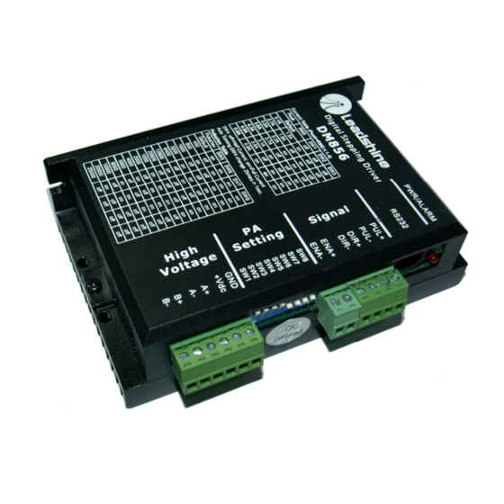
DM856
improve reliability, function or design. Leadshine does not assume any liability arising out of the
application or use of any product or circuit described herein; neither does it convey any license
under its patent rights of others.
Fully Digital Stepping Driver
Leadshine's general policy does not recommend the use of its products in life support or aircraft
Version 1.0
applications wherein a failure or malfunction of the product may directly threaten life or injury.
©2009 All Rights Reserved
According to Leadshine's terms and conditions of sales, the user of Leadshine's products in life
Attention: Please read this manual carefully before using the driver!
support or aircraft applications assumes all risks of such use and indemnifies Leadshine against all
damages.
3/F, Block 2, Nanyou Tianan Industrial Park, Nanshan Dist, Shenzhen, China
©2009 by Leadshine Technology Company Limited.
T: (86)755-26434369
F: (86)755-26402718
All Rights Reserved
Web site:
www.leadshine.com
E-Mail:
sales@leadshine.com
Advertisement
Table of Contents

Related Manuals for Leadshine Technology DM856


Summary of Contents for Leadshine Technology DM856
- Page 1 Leadshine against all damages. 3/F, Block 2, Nanyou Tianan Industrial Park, Nanshan Dist, Shenzhen, China ©2009 by Leadshine Technology Company Limited. T: (86)755-26434369 F: (86)755-26402718 All Rights Reserved Web site: www.leadshine.com...
-
Page 2: Table Of Contents
Contents Contents Table of Contents Dynamic current setting ................10 Standstill current setting................10 1. Introduction, Features and Applications..............1 8. Wiring Notes ......................10 Introduction ......................1 9. Typical Connection....................11 Features ......................... 1 10. Sequence Chart of Control Signals ............... 11 Applications ...................... -
Page 3: Introduction, Features And Applications
It is recommended to mount the driver vertically to maximize heat sink area. Use forced cooling and so on. Its unique features make the DM856 an ideal solution for applications that require both method to cool the system if necessary. -
Page 4: Operating Environment And Other Specifications
Pin Function Details output). The DM856 has 3 optically isolated logic inputs which are located on connector P1 to accept Pulse signal: In single pulse (pulse/direction) mode, this input represents pulse signal, each rising or falling edge active (software configurable); 4-5V when PUL+ line driver control signals. -
Page 5: Connecting The Motor
5. Connecting the Motor motors should be run at only 70% of their rated current to prevent over heating. The DM856 can drive any 2-pahse and 4-pahse hybrid stepping motors. Connections to 4-lead Motors 4 lead motors are the least flexible but easiest to wire. Speed and torque will depend on winding Figure 6: 6-lead motor full coil (higher torque) connections inductance. -
Page 6: Parallel Connections
7. Selecting Microstep Resolution and Driver Output Current The DM856 can match medium and small size stepping motors (from NEMA frame size 17 to 34) made by Leadshine or other motor manufactures around the world. To achieve good driving Microstep resolutions and output current are programmable, the former can be set from full-step to performances, it is important to select supply voltage and output current properly. -
Page 7: Current Settings
DM856 Digital Stepping Driver Manual V1.0 DM856 Digital Stepping Driver Manual V1.0 Microstep Steps/rev.(for 1.8°motor) Dynamic current setting Peak Current RMS Current 1 to 512 Default/Software configured Default/Software configured (0.5 to 5.6A) 2.1A 1.5A 2.7A 1.9A 1600 3.2A 2.3A 3200 6400 3.8A... -
Page 8: Typical Connection
Low level width not less than 2.5µs. 11. Protection Functions To improve reliability, the driver incorporates some built-in protection functions. The DM856 uses one RED LED to indicate what protection has been activated. The periodic time of RED is 3 s (seconds), and how many times the RED turns on indicates what protection has been activated. -
Page 9: Protection Indications
DM856 Digital Stepping Driver Manual V1.0 DM856 Digital Stepping Driver Manual V1.0 Problem Symptoms and Possible Causes Protection Indications Priority Time(s) of ON Sequence wave of RED LED Description Symptoms Possible Problems No power Over-current protection Microstep resolution setting is wrong... -
Page 10: Professional Tuning Software Protuner
This section will provide an overview of connection and basic setup instructions for Leadshine’s digital stepping driver DM856 using the ProTuner software. These instructions will walk you through the following steps necessary to start up your driver and motor. This section is intended for setting up the driver with the ProTuner. - Page 11 DM856 Digital Stepping Driver Manual V1.0 DM856 Digital Stepping Driver Manual V1.0 Figure 14: Installation folder settings Figure 16: Installation information summarization Figure 15: Shortcut folder setting Figure 17: Installing the ProTuner Set the “Shortcut Folder” in Figure 15 and continue to install the ProTuner by following Figure 16 and Figure 17.
-
Page 12: Connections And Testing
Ø Option Turn on the power supply, the green (Power) LED will light. The DM856 has default parameters The user can choose three drop-down menus by clicking “Option”, including Com Config, stored in the driver. If the system has no hardware and wirings problem, the motor should be locked SaveToDriver and Exit. -
Page 13: Com Config Window
DM856 Digital Stepping Driver Manual V1.0 DM856 Digital Stepping Driver Manual V1.0 Exit: Exit the ProTuner. Com Config Window Figure 21: RS232 communication configuration window Serial Port: Select the serial communication port to which the driver is connected. The factory default Figure 22: Current Tuning window setting is COM1. - Page 14 However, if the user does not want to tune the current loop after changing a different stepping motor, then Motor auto-identification and parameter auto-configuration technology of the DM856 can replace manual tuning the driver with ProTuner. Just changes SW4 two times in 1 second, and then...
-
Page 15: Anti-Resonance Introduction
Step 1: Start the motion test by clicking Start/Stop button. Find an resonance speed by slightly DM856 driver provides robust anti-resonance control to stop the vibrations and maintain equilibrium. moving the slider bar of internal pulse generator back and forth. See Figure 26. - Page 16 DM856 Digital Stepping Driver Manual V1.0 DM856 Digital Stepping Driver Manual V1.0 OverVoltage: Over-voltage Protection. When power supply voltage exceeds 91±1 VDC, protection will be activated. PhaseErr: Phase Error Protection. Motor power lines wrong & not connected will activate this protection.
-
Page 17: Appendix
Please include a written description of the problem along with contact name and address. Send failed product to distributor in your area or: Leadshine Technology Co., Ltd. 3/F, Block 2, Nanyou Tianan Industrial Park, Nanshan Dist, Shenzhen, China. Also enclose information regarding the circumstances prior to product failure.
Need help?
Do you have a question about the DM856 and is the answer not in the manual?
Questions and answers