
Related Manuals for NEC startWARE-GHS-Ravin-E


Summary of Contents for NEC startWARE-GHS-Ravin-E
- Page 1 User’s Manual startWARE-GHS-Ravin-E Ravin-E Add-on Board for startWARE-GHS-V 4131 and startWARE-GHS-V 4133 Document No. U17316EE1V0UM00 Date Published September 2004 NEC Corporation 2004 Printed in Germany...
- Page 2 NOTES FOR CMOS DEVICES PRECAUTION AGAINST ESD FOR SEMICONDUCTORS Note: Strong electric field, when exposed to a MOS device, can cause destruction of the gate oxide and ultimately degrade the device operation. Steps must be taken to stop generation of static electricity as much as possible, and quickly dissipate it once, when it has occurred.
- Page 3 NEC Electronics products listed in this document or any other liability arising from the use of such NEC Electronics products. No license, express, implied or otherwise, is granted under any patents, copyrights or other intellectual property rights of NEC Electronics or others.
- Page 4 Some information contained in this document may vary from country to country. Before using any NEC product in your application, please contact the NEC office in your country to obtain a list of authorized representatives and distributors. They will verify: •...
-
Page 5: Preface
Preface Readers This manual is intented for users who want to understand the functions of the startWARE-GHS-Ravin-E. Purpose This manual presents the hardware manual of startWARE-GHS-Ravin-E. Organization This system specification describes the following sections: • Pin function • CPU function •... - Page 6 User’s Manual U17316EE1V0UM00...
-
Page 7: Table Of Contents
Schematics ........35... - Page 8 User’s Manual U17316EE1V0UM00...
- Page 9 List of Figures Figure 2-1: startWARE-GHS-Ravin-E Board ................. 16 Figure 3-1: startWARE-GHS-Ravin-E Block Diagram ..............17 Figure 5-1: Board Outline and Component Placement ..............23 Figure 5-2: Host Connector CN1 ....................24 Figure 5-3: Video Connectors CN8 and CN9 ................27 Figure 5-4: VGA Connector CN12 ....................
- Page 10 User’s Manual U17316EE1V0UM00...
- Page 11 List of Tables Table 3-1: Operating Currents under typical operating conditions ..........18 Table 5-1: Technical Data of the Ravin-E Board ................23 Table 5-2: Host Connector CN1 ...................... 24 Table 5-3: VGA Connector CN12 ....................28 Table 5-4: Digital video output connector CN13 ................30 Table 5-5: JTAG interface connector CN14..................
- Page 12 User’s Manual U17316EE1V0UM00...
-
Page 13: Introduction
1.2 Package Contents Please verify that you have received all parts listed in the package contents list attached to the startWARE-GHS-Ravin-E package. If any part is missing or seems to be damaged, please contact the dealer from whom you purchased your startWARE-GHS-Ravin-E. - Page 14 [MEMO] User’s Manual U17316EE1V0UM00...
-
Page 15: Board Features
Chapter 2 Board Features As the name implies, the startWARE-GHS-Ravin-E board employs the Ravin-E display controller (µPD72255) as its centrepiece. Also implemented is an SAA7113H or SAF7113H video processor, which is used to digitize a PAL or NTSC standard video signal and optionally overlay it on the graphics. -
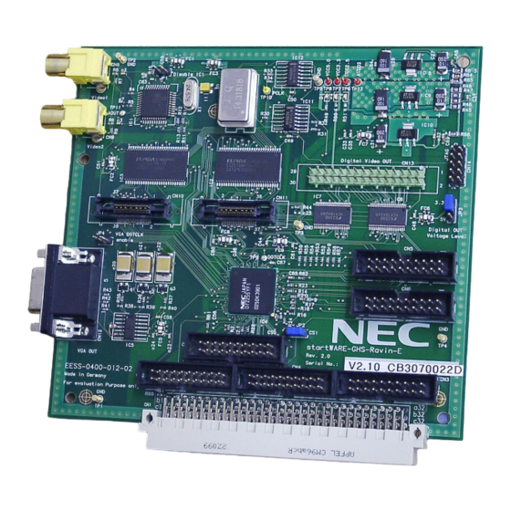
Page 16: Picture Of Startware-Ghs-Ravin-E Board
Chapter 2 Board Features 2.2 Picture of startWARE-GHS-Ravin-E Board Figure 2-1: startWARE-GHS-Ravin-E Board User’s Manual U17316EE1V0UM00... -
Page 17: Functional Description
CRT or TFT displays. Ravin-E can be connected to virtually any 32-bit host CPU with an asynchronous SRAM-like bus interface. A second 32-bit wide data bus connects to standard SDRAMs which serve as the frame buffer for the graphics and the video. Figure 3-1: startWARE-GHS-Ravin-E Block Diagram SAA7113H 8-bit... -
Page 18: Power Consumption
Ravin-E is the second one. 3.1 Power Consumption The startWARE-GHS-Ravin-E board is supplied with a single +5 V DC operating voltage from the main board. The internally required 3.3 V and 2.5 V are generated by linear voltage regulators on the Ravin-E board. -
Page 19: Software Description
We have written a few demo programs, which can be found in the “Software\Ravin-E” directory of the startWARE-GHS-Ravin-E CD. The programs can be compiled for MIPS RISC devices or for V850E devices. Build files for each of these environments are supplied. We have used Green Hills version 3.5.1 for V850 and version 3.6.1 for MIPS. -
Page 20: Display Of Png Files
Chapter 4 Software Description 4.2 Display of PNG Files In order to display png files (Portable Network Graphics), we have ported the free PNG Reference Library libpng (www.libpng.org) to the V850. This library requires the zlib compression library (www.gzip.org), which has also been ported. These two libraries are documented on their respective websites. -
Page 21: Demonstration Programs
Ravin-E's frame buffer instead of the heap. The total size of the frame buffer on the startWARE-GHS-Ravin-E board is 64 MB which is plenty of space outside the current display area. Transfer of the image to the screen location would then be accomplished by a BITBLT command to Ravin-E. -
Page 22: Benchmarks
“os_sleep(20)” delay at the end of function main. 4.4.4 HW-Test HW-Test is a program, which is used by NEC in the startWARE-GHS-Ravin-E production test. It per- forms an initial test of the Ravin-E frame buffer memory, displays some vectors with colour shading on the screen and captures a video via the cinch connectors. -
Page 23: Appendix
Chapter 5 Appendix This chapter collects the technical data of the board. Detailed explanations are therefore reduced to a minimum. Figure 5-1: Board Outline and Component Placement D1/2/3 CN13 LEDs for deselect digital Video output 5.0 V/3.3 V/2.5 V video processor Video in 1 CN14 JTAG... -
Page 24: Description Of Connectors And Jumpers
DATA23 in/out data bus signal 23 ground DATA19 in/out data bus signal 19 Note: Signal direction as seen from startWARE-GHS-Ravin-E board (e.g. “in” is an input on this board and must be driven by the main board) User’s Manual U17316EE1V0UM00... -
Page 25: Table 5-2: Host Connector Cn1
21 ADD16 address bus signal 16 ADD17 address bus signal 17 Note: Signal direction as seen from startWARE-GHS-Ravin-E board (e.g. “in” is an input on this board and must be driven by the main board) User’s Manual U17316EE1V0UM00... - Page 26 PCICLK PCI clock (connect to GND if asynchronous interface) ground n.c. unconnected Note: Signal direction as seen from startWARE-GHS-Ravin-E board (e.g. “in” is an input on this board and must be driven by the main board) User’s Manual U17316EE1V0UM00...
-
Page 27: Video Connectors Cn8 And Cn9
41xx mode; 1: BEBn inputs are write strobe signals n.c. unconnected Note: Signal direction as seen from startWARE-GHS-Ravin-E board (e.g. “in” is an input on this board and must be driven by the main board) 5.1.2 Video Connectors CN8 and CN9 Standard Cinch connectors are used to input the composite video signals for the two video channels 1 and 2. -
Page 28: Vga Connector Cn12
Chapter 5 Appendix 5.1.3 VGA Connector CN12 CN12 is a 15-pin female high density Sub-D connector. It has a pin configuration so that a standard VGA monitor can be connected. The RGB signal voltages have levels between 0 and 0.7 V , while the synchronization signals are 5 V TTL compatible. -
Page 29: Digital Video Output Connector Cn13
Chapter 5 Appendix 5.1.4 Digital video output connector CN13 CN13 carries the signals for a digital TFT display. Its signal output voltages are selectable by JP3 to 3.3 V or 5 V. Figure 5-5: Digital video output connector CN13 User’s Manual U17316EE1V0UM00... -
Page 30: Table 5-4: Digital Video Output Connector Cn13
Chapter 5 Appendix Table 5-4: Digital video output connector CN13 Number Name Direction Description Note Ravin-E FSC output Note PLLREF Ravin-E PLLREF output VCC33 3.3 V power supply VCC50 5.0 V power supply Blue 1 Blue 2 Blue 3 Blue 4 Blue 5 Ground Green 0... -
Page 31: Jtag Interface Connector Cn14
Chapter 5 Appendix 5.1.5 JTAG interface connector CN14 CN14 is the JTAG interface connector. The scan chains of the SAA7113 and Ravin-E are linked, with the SAA7113 being the first in the chain and Ravin-E the second. Figure 5-6: JTAG interface connector CN14 Table 5-5: JTAG interface connector CN14 Number Name... -
Page 32: Disable Video Processor With Jp1
Chapter 5 Appendix 5.1.6 Disable Video Processor with JP1 When a jumper is plugged onto JP1, then the video processor is de-selected. This feature has been implemented so that an external video processor can access the video input port of Ravin-E. JP1 is normally not used. -
Page 33: Select Digital Video Signal Voltage With Jp3
Chapter 5 Appendix 5.1.8 Select digital video signal voltage with JP3 The digital video output signals on CN13 can drive either 3.3 V LVTTL or 5 V TTL compatible devices. JP3 selects between these two voltages. Figure 5-9: Jumper JP3 Table 5-7: Jumper Settings with JP3 Jumper setting Function... -
Page 34: Address Map
HostCpuBaseAddr. The start address is aligned to a 2 kB base address. When the startWARE-GHS-Ravin-E board is used together with the startWARE-GHS-V 4131 board, then the following address mapping in the V... -
Page 35: Startware-Ghs-Ravin-E Schematics
Chapter 5 Appendix 5.3 startWARE-GHS-Ravin-E Schematics Figure 5-11: Ravin-E User’s Manual U17316EE1V0UM00... -
Page 36: Figure 5-12: Connectors
Chapter 5 Appendix Figure 5-12: Connectors User’s Manual U17316EE1V0UM00... -
Page 37: Pci Adapter Schematics
Chapter 5 Appendix 5.4 PCI Adapter Schematics This adapter is not included in the startWARE-GHS-Ravin-E package. Figure 5-13: VME-PCI Adapter CON1 n.c. IDSEL CON2 n.c. n.c. n.c. -12V TRST# n.c. n.c. +12V n.c. n.c. n.c. n.c. n.c. INTA# INTA# n.c. - Page 38 [MEMO] User’s Manual U17316EE1V0UM00...
- Page 39 Facsimile Message Although NEC has taken all possible steps to ensure that the documentation supplied to our customers is complete, bug free and up-to-date, we readily accept that From: errors may occur. Despite all the care and precautions we've taken, you may Name encounter problems in the documentation.