
Related Manuals for Sime SOLIDA 5 PL


Summary of Contents for Sime SOLIDA 5 PL
- Page 1 SOLIDA 5 PL / 8 PL + SOLIDA 5 PL: cod. 8058540 Kit pellet SOLIDA 5 PL cod. 8075950 SOLIDA 8 PL +: cod. 8075742 Kit pellet SOLIDA 8 PL + cod. 8075960...
-
Page 2: Table Of Contents
INDICE FUNZIONAMENTO A LEGNA O CARBONE DESCRIZIONE................INSTALLAZIONE . -
Page 3: Funzionamento A Legna O Carbone
M Man da ta im pian to 2” (UNI-ISO 7/1) R Ri tor no im pian to 2” (UNI-ISO 7/1) S Scarico caldaia 1/2” (UNI-ISO 7/1) SOLIDA 5 PL SOLIDA 8 PL + 555 mm 855 mm Fig. 1 390 mm 690 mm 1. -
Page 4: Installazione
po ten za del la cal daia in kcal/h vaso di espansione dovranno corrispondere, INSTALLAZIONE al tez za del ca mi no in me tri mi su ra ta o comunque non essere inferiori, all’altez- dal l’as se del la fiam ma al lo sca ri co del za della colonna statica dell’impianto (ad 1.2. - Page 5 LE GEN DA 1 Maniglia 2 Porta di carico 3 Rullino 4 Coppiglia elastica Fig. 4 – Togliere la cartella di ghisa agendo ester- tamente i fianchi del mantello. Nei tiranti inferiori sia dalla parte anteriore namente con uno scalpello, sul lato sinistro della testata anteriore, come indicato al che nella parte posteriore della caldaia, sono LE GEN DA...
- Page 6 fissa la leva con catenella fare attenzione a rimontarlo nella medesima posizione. Regolatore “THERMOMAT RT-C” Dopo aver posizionato la manopola su 60°C bloccare la leva con catenella in posizione leggermente inclinata verso il basso in modo che la catenella venga a trovarsi in asse con l’attacco della serranda aria.
-
Page 7: Uso E Manutenzione
Impianto a vaso espansione chiuso e scambiatore di sicurezza con valvola termostatica optional LE GEN DA VE Vaso espansione VS Valvola sicurezza impianto 3 BAR - 1/2” VM Valvola miscelatrice VR Valvola di ritegno PI Pompa impianto IR Impianto di riscaldamento VT Valvola termostatica SC Scambiatore di sicurezza F Filtro... -
Page 8: Funzionamento A Pellet Con Apposito Kit
242x272x4 n° 1 n° 1 Contenitore con scivolo pellet in legno 2. 1 . 1 DIMENSIONI D’INGOMBRO SOLIDA 5 PL SOLIDA 8 PL + 1435 mm 1735 mm 1260 mm 1560 mm Fig. 12 2. 1 .2... -
Page 9: Installazione
INSTALLAZIONE 2.2. 1 ADATTAMENTO CALDAIA PER IL FUNZIONAMENTO A PELLET CON KIT OPZIONALE Togliere la flangia cieca in ghisa della caldaia e smontare la griglia, la cerniera e il nasello con relative viti di fissaggio. Fig. 13 Smontaggio flangia cieca Fig. - Page 10 Collocare i rimanenti supporti laterali anteriori ed appoggiare le tavelle in cemento Supporti laterali Tavelle in cemento Fig. 19 Fig. 20 ATTENZIONE! LE TAVELLE DI CEMENTO DEVONO ESSERE ADIACENTI ALLA PARTE ANTERIORE DELLA CALDAIA Collocare l’ultimo deflettore in ghisa 3° deflettore Fig.
- Page 11 Posizionare l’isolante in lana di roccia sul canotto bruciatore (vedi Fig. 24) Fig. 24 Isolante Montare il bruciatore e fissarlo con i 2 dadi flangiati M10 Montaggio bruciatore Fissaggio bruciatore Fig. 25 Fig. 26 ATTENZIONE! SERRARE I DADI AFFINCHÉ LA PIASTRA DEL BRUCIATORE SI APPOGGI ALLA FLANGIA DELLA CALDAIA. NON STRINGERE OLTRE.
- Page 12 Togliere il termometro e tappare il foro del pannello Togliere il termometro Tappare il foro Fig. 29 Fig. 30 Bloccare la portina aspirazione se in precedenza la caldaia era stata utilizzata per il funzionamento a legna o carbone Portina aspirazione Fig.
- Page 13 Montaggio serbatoio da 80 kg Pos. Descrizione N° tubo coclea dado M8 flangia coclea rondella M8 bullone M8x20 serbatoio base serbatoio bullone M8x30 Fig. 32 Montaggio serbatoio e coclea...
- Page 14 2.2.2 ALLACCIAMENTI ELETTRICI Collegare il connettore del cavo (1), proveniente dal motore della coclea, al bruciatore Collegare il connettore del cavo (2), proveniente dal bruciatore, al termostato di sicurezza Cavo motore coclea Connettore termostato di sicurezza Fig. 33 Fig. 34 Collocare la sonda di mandata (3) nella guaina (4) presente sul corpo caldaia Sonda mandata Sonda mandata...
-
Page 15: Schema Elettrico
SCHEMA ELETTRICO 230V ~ 50Hz Alimentazione elettrica SPIRALE Collegamenti a cura VENTILATORE ACCENSIONE dell’installatore FOTORESISTENZA CARICATORE PELLET t° SCHEDA PRINCIPALE HI-LIMIT 1 SCHEDINO FLUSSOSTATO TERMOSTATO IDRO (SCAMBIATORE SANITARIO A PIASTRE) (BOLLITORE) J5 J4 POMPA SPIA / SPIA VALVOLA SIRENA ALLARME DEVIATRICE ALLARME IDRO... - Page 16 SCHEDA SECONDARIA HI-LIMIT 2 TERMOSTATO DI t° SICUREZZA SONDA NTC POSSIBILITÀ DI COLLEGAMENTO: di un Termostato ambiente (TA) di un comando remoto ON/OFF (CR) Fig. 39...
-
Page 17: Bruciatore Di Pellet
BRUCIATORE DI PELLET 2.4. 1 DESCRIZIONE LEGENDA Corpo del bruciatore Motore ventilatore - SOLIDA 5 PL : RLD85/0034 A7-302020LH-502 ki 220-240V AC 50 HZ - 35W - SOLIDA 8 PL + : RLG97/0042 A16-30252LH-502 ahs 220-240V AC 50 HZ - 38W... - Page 18 2.4.3 ADESIVO THERMOSTICKER BRUCIATORE Il thermosticker viene utilizzato per misu- rare la temperatura di funzionamento °C °C del corpo del bruciatore in una zona precisa. La misurazione della temperatu- °F °F ra fornisce indirettamente informazioni in merito alla condizione del sistema di riscaldamento e alla necessità...
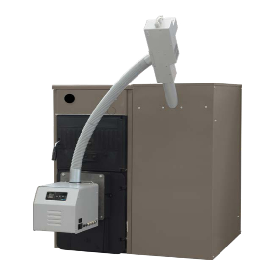
- Page 19 2.4.5 BRUCIATORE E CARICATORE DI PELLET Motore coclea Tubo flessibile di collegamento Coclea Bruciatore Apertura di caricamento Fig. 44 2.4.6 ASSIEME CALDAIA E CONTENITORE DEL PELLET Tubo flessibile autoestinguente Alimentatore con motore coclea Caldaia SOLIDA PL Coclea Contenitore pellet da 80 kg Pannello di controllo Bruciatore Fig.
- Page 20 2.4.7 CARATTERISTICHE DEL PELLET Descrizione Unità di misura Valore Dimensioni pellet 6 – 8 Potere calorifico MJ/kg >17,2 netto raccomandato kWh/kg >4,7 Classe (ENplus) ENplus-A1 Categoria pellet A, AB, B* Residuo in cenere Vedere Tabella 2 Umidità Max. 8 – 10% Tabella 1 Proprietà...
- Page 21 L’approvazione del nuovo standard europeo per il pellet (EN 14961-2) introduce i nuovi certificati: ENplus per pellets impiegati in apparecchi per il riscaldamento domestico; EN-B per caldaie industriali. La norma definisce le classi ENplus del pellet di legno in A1 e A2. La classe A1 introduce limiti più severi per il possibile residuo in cenere. La classe A2 permette un contenuto di residui in cenere fino a 1,5%.
-
Page 22: Uso E Manutenzione
USO E MANUTENZIONE 2.5. 1 PANNELLO DI CONTROLLO Il pannello display è un pannello di controllo per stufe a pellet e biomasse ad aria o ad aria- acqua, con integrate una sonda di tempe- ratura e un orologio per eseguire le funzioni di cronotermostato. Il pannello (Vedi “Fig. - Page 23 Dopo circa 12s si passa alla schermata di “AVVIO” (Vedi Fig. 48) che indica l’effettivo stato operativo della caldaia. H 2 O 1 0 : 2 3 O F F > Fig. 48 Schermata AVVIO Nella prima riga di tale schermata viene visualizzata la temperatura misurata (con risoluzione 0,5°C) e l’ora (Vedi Fig. 49). Nella seconda riga si alternano ogni 2s le scritte che descrivono lo stato della caldaia e qualora siano attivate, le funzioni abilitate (Tabella 4) e/o l’eventuale presenza di anomalie;...
- Page 24 2.5.2.3 ACCENSIONE/SPEGNIMENTO DELLA CALDAIA L’accensione (o lo spegnimento) della caldaia avviene premendo per almeno 2s il tasto ON/OFF (Tasto 5) durante la visualizzazione della schermata AVVIO, il pannello emette un cicalino di conferma e lo stato della caldaia visualizzato cambierà adeguandosi allo stato effettivo. 2.5.3 FUNZIONI IMMEDIATE La pressione di uno dei 4 tasti laterali durante la visualizzazione della schermata AVVIO permette l’accesso alla schermata SELEZIONE...
- Page 25 2.5.4 FUNZIONI AVANZATE Alla pressione del tasto Menu (Tasto 3) si può accedere alle “Funzioni avanzate”: sulla riga inferiore compare il nome della funzione che si sta visua- lizzando; sulla riga superiore compare il valore del dato corrispondente salvato. Qualora non vi sia alcun valore sulla riga superiore, la voce indicata sulla riga inferiore si riferisce ad un sottomenù...
- Page 26 Funzione Valore 00 ÷ 23 Minuti 00 ÷ 59 Giorno Lu ÷ Do Giorno Num. 00 ÷ 31 Mese 01 ÷ 12 Anno 2010 ÷ 2109 Elenco funzioni Data e Ora Tabella 7 2.5.4.3 FUNZIONE CRONO La funzione crono permette di impostare fino a 6 programmi di accensione/spegnimento automatico della caldaia; ogni programma può essere asse- gnato a ciascun giorno della settimana, così...
- Page 27 2.5.4.4 FUNZIONE IMPOSTAZIONI Il menu impostazioni, come il Menù principale, indica un insieme di dati e parametri e di sottomenù, quindi, come tale, rispecchia le stesse carat- teristiche nonché le stesse modalità di gestione. In Tabella 10 sono elencate le funzioni ed i sottomenù nell’ordine in cui compaiono con i rispettivi valori modificabili. Funzione Valore Lingua...
- Page 28 CARICA COCLEA La funzione “Carica coclea” è visualizzata nel menu solo ed esclusivamente se la caldaia si trova nello stato OFF ed il suo scopo è quello di abilitare la logica della scheda che permette la riempire la coclea con il pellet. Alla pressione del tasto Set (Tasto 3) il pannello cambia schermata (Vedi “Fig.
- Page 29 Sulla riga inferiore compare il nome della funzione che si sta visualizzando; se le scritte sono troppo lunghe per essere visualizzate per intero, scorreranno fino a che non saranno totalmente visualizzate. I parametri seguono l’ordine riportato in Tabella 12. Menu Sottomenu Valori Impostazioni Generali...
- Page 30 Menu Collaudo Bypass Accensione Reset Collaudo Coclea Espulsore Fan 1 Fan 2 Pompa Candeletta Taratura On Fotores. Taratura Off Fotores. Tabella 12 Elenco funzioni Menu Tecnico Questo valore è impostabile a 2 solo se il secondo espulsore è disabilitato. Il valore massimo visualizzabile dipende dal valore impostato, gestito dalla scheda. *** Questa funzione è...
- Page 31 2.5.4.6 MENU INFO UTENTE Il menu Info Utente contiene un insieme di valori e parametri relativi al funzionamento della scheda e ad alcuni componenti ad essa collegati; tutti i valori in questione non sono modificabili, per questo motivo, nella prima riga non compare la scritta Set/Ok, ma solo la scritta esc. Sulla riga inferiore compare il nome del parametro di cui si sta visualizzando il valore.
- Page 32 2.5.4.7 ANOMALIE Il menu Anomalie appare solo ed esclusivamente se si è in una situazione di “warning” o meglio se ci si trova in una situazione in cui l’allarme “non è bloccante”. L’ingresso alla lista delle anomalie presenti in caldaia è accedibile tramite la pressione del tasto Set (Tasto 3), nell’eventualità che siano presenti più anomalie, è...
- Page 33 Premendo il tasto info (Tasto 1) compare la schermata di descrizione problema (Fig. 59). e s c A L L A R M E A 0 1 R i t e n t a r e c h i a Schermata ALLARME 3 Fig.
- Page 34 2.5.6 PULIZIA (Fig. 60) Le operazioni di pulizia devono essere ese- guite con una certa frequenza e solo con caldaia completamente fredda. Per la pulizia dei residui della combustione la caldaia è fornita di un cassetto estraibile che deve essere svuotato prima di ogni accensio- ne.
- Page 35 2.5.8 ACCESSORI KIT ACCESSORI: - 5197500 SERBATOIO PELLET DA 200 L - 5197510 SERBATOIO PELLET DA 300 L - 5197520 SERBATOIO PELLET DA 500 L...
-
Page 36: Garanzia Convenzionale
ELENCO CENTRI ASSISTENZA (aggiornato al 05/2012) VENETO Melzo Novellini 02 95301741 Brà Testa Giacomo 0172 415513 Paderno Dugnano S.M. 02 99049998 Brà Edmondo Dario 0172 423700 Pieve Emanuale Thermoclimat 02 90420195 Fossano Eurogas 0172 633676 VENEZIA Pogliano M.se Gastecnica Peruzzo 02 9342121 Margarita Tomatis Bongiovanni 0171 793007... - Page 37 Empoli Sabic 0571 929348 Ficulle Maschi Adriano 0763 86580 Amantea Di Maggio Gaetano 0982 424829 Empoli Clima Casa 0571 710115 Orvieto Alpha Calor 0763 393459 Belvedere Marittimo Tecnoimpianti s.r.l. 0985 88308 Fucecchio S.G.M. 0571 23228 Morano Calabro Mitei 0981 31724 MARCHE Signa 055 8790574...
-
Page 38: Elenco Centri Assistenza
5 anni dalla data di messa in commercio del- scrizione delle condizioni di garanzia ne determina la nullità. l’apparecchio. Fonderie SIME SpA si riserva di variare in qualunque momento e senza preavviso i propri prodotti nell’intento di migliorarli senza pregiudicarne le caratte- ristiche essenziali. 38 38... - Page 39 INDEX OPERATION WOOD AND CARBON 1. 1 DESCRIPTION ..................INSTALLATION.
- Page 40 DIMENSIONS FIXTURES M C.H. flow 2” (UNI-ISO 7/1) R C.H. return 2” (UNI-ISO 7/1) S Boiler drain 1/2” (UNI-ISO 7/1) SOLIDA 5 PL SOLIDA 8 PL + 555 mm 855 mm Fig. 1 390 mm 690 mm 1. 1 .4...
- Page 41 boiler capacity in kcal/h should correspond or however shouldn’t be INSTALLATION H height of the chimney in meters inferior to the height of the static column measured from the flame axis at the of the plant in case of closed circuit heating 1.2.
- Page 42 LEGEND Handle Load port Roll Elastic split pin Fig. 4 the hub (9), fixing then everything with the ceed in the same way. washer (2) and the screw (1). – Hook the front upper board (3) intro- ducing the two splines in the opening, LEGEND obtained on each side.
- Page 43 – Place the knob at 60°C. – Switch on the boiler with opened air gate “THERMOMAT RT-C” Regulator damper. – When the water temperature of 60° C is reached in the boiler, fix the chainlet in such a way on the lever of the air gate damper, in order to obtain an opening of about 1 mm.
- Page 44 Closed expansion tank system with heat exchanger and optional thermostat valve LE GEN D VE Expansion tank VS System safety valve 3 BAR - 1/2” VM Mixing valve VR Check valve PI System pump IR Heating system VT Thermostat valve SC Safety exchanger F Filter CAUTION: The safety exchanger is supplied in an...
- Page 45 EN 303-5. Container with 80-kg wood pellet slide. 242x272x4 gasket n° 1 n° 1 2. 1 . 1 OVERALL DIMENSIONS SOLIDA 5 PL SOLIDA 8 PL + 1435 mm 1735 mm 1260 mm 1560 mm Fig. 12 2.1.2...
- Page 46 INSTALLATION 2.2. 1 BOILER ADAPTATION FOR OPERATION WITH PELLETS AND SPECIAL KIT Remove the cast iron blind plate on the boiler and remove the grille, tie rod and latch with the relative screws. Fig. 13 Remove the blind plate Fig. 14 Remove the grille Place the cast iron deflector with the rear side supports Fig.
- Page 47 Place the remaining front lateral supports and insert the cement bricks Lateral supports Cement bricks Fig. 19 Fig. 20 WARNING! THE CEMENT BRICKS MUST BE ADJACENT TO THE FRONT PART OF THE BOILER Place the last cast iron deflector deflector Fig.
- Page 48 Place the rock wool insulation on the burner sleeve (See Fig. 24) Fig. 24 Insulation Assemble the burner and fix it with the 2 M10 flange nut Burner assembly Fixing of the burner Fig. 25 Fig. 26 WARNING! TIGHTEN THE NUTS UNTIL THE BURNER PLATE RESTS ON THE BOILER PLATE. DO NOT TIGHTEN TOO MUCH.
- Page 49 Remove the thermometer and plug the panel hole Remove the thermometer Plug the hole Fig. 29 Fig. 30 Block the suction door if the boiler was previously used for operation with wood or carbon Suction door Fig. 31 WARNING! OPEN THE LOADING DOOR ONLY WHEN THE BURNER IS TURNED OFF.
- Page 50 Assembly of an 80-kg tank Pos. Description screw feeder tube M8 nut screw feeder ring M8 washer M8x20 bolt tank tank base M8x30 bolt Fig. 32 Tank and screw feeder assembly...
- Page 51 2.2.2 ELECTRICAL CONNECTIONS Connect the cable connector (1) coming from the screw feeder motor to the burner Connect the cable connector (2) coming from the burner to the safety thermostat Screw feeder motor cable Safety thermostat connector Fig. 33 Fig. 34 Place the inlet joint (3) in the sheath (4) found on the boiler body Inlet joint Inlet joint...
- Page 52 WIRING DIAGRAM 230V~50Hz Electrical supply Connections to be IGNITION made by the installer COIL VENTILATOR PHOTORESISTOR PELLET LOADER t° MAIN BOARD HI-LIMIT 1 HYDRO FLOW SWITCH SANITARY BOARD (PLATE HEAT THERMOSTAT EXCHANGER) (CHAMBER) J5 J4 WARNING HYDRO 3-WAY PUMP LIGHT/ALARM ALARM DIVERTER SIREN...
- Page 53 SECONDARY BOARD HI-LIMIT 2 SAFETY t° THERMOSTAT NTC SENSOR CONNECTION OPTION: • an ambient thermostat (AT) • a remote control ON/OFF (CR) Fig. 39...
- Page 54 PELLET BURNER 2.4. 1 DESCRIPTION Burner body Fan motor - SOLIDA 5 PL : RLD85/0034 A7-302020LH-502 ki 220-240V AC 50 HZ - 35W - SOLIDA 8 PL + : RLG97/0042 A16-30252LH-502 ahs 220-240V AC 50 HZ - 38W Brazier Pellet grille...
- Page 55 2.4.3 BURNER THERMOSTICKER The thermosticker is used to measure the operating temperature of the burner °C °C body in a certain area. The temperature measurements provide indirect informa- °F °F tion regarding the condition of the heating system and the need for preventive action or maintenance of the burner and exhaust Viewing of the sticker with the temperature of the combustion chamber under ducts.
- Page 56 2.4.5 PELLET BURNER AND LOADER Screw feeder motor Flexible connection tube Screw feeder Burner Loading aperture Fig. 44 2.4.6 BOILER AND PELLET CONTAINER ASSEMBLY Self-extinguishing flexible tube Power pack with screw feeder motor SOLIDA PL boiler Screw feeder 80-kg pellet container Control panel Burner Fig.
- Page 57 2.4.7 CHARACTERISTICS OF THE PELLETS Description Unit of measurement Value Size of the pellets 6 – 8 Recommended net calorific value MJ/kg >17.2 kWh/kg >4.7 Class (ENplus) ENplus-A1 Pellet category A, AB, B* Ash residue See Table 2 Humidity Max. 8 – 10% Properties recommended for wood pellets Table 1...
- Page 58 The approval of the new European standard for pellets (EN 14961-2) has introduced new certificates: ENplus for pellets used in devices for domestic heating; EN-B for industrial boilers. The standard defines the ENplus wood pellet classes in A1 and A2. The A1 class introduces more severe limits on the possible ash residue. The A2 class allows for a ash residue content up to 1.5%.
- Page 59 USE AND MAINTENANCE 2.5. 1 DISPLAY PANEL The display panel is a control panel intended for controlling pellet or biomass feeded furnaces or boilers, integrating a temperature sensor and a RTC used to turn on or off the controlled heater at preset hours. The panel (See “Fig.
- Page 60 After about 12s the “START” screen appears (See Fig. 48); this means that the system is ready. H 2 O 1 0 : 2 3 O F F > Fig. 48 START screen On the top line the current temperature (resolution 0,5°C) and the time are shown (See Fig. 49). On the bottom line the system alternates every 2s the text strings describing the controlled heater current status, the active functions (Table 4) and the active alarms, if any;...
- Page 61 2.5.2.3 HEATER FIRING UP/SHUTTING DOWN Firing (or shutting-down) the controlled heater is accomplished by pressing the ON/OFF key (key #5) from within the START screen; the panel will beep and the displayed status will be updated. 2.5.3 QUICK ACCESS FUNCTIONS By pressing one of the 4 side buttons from within the START screen changes the display to the SELECTION screen (See Fig.
- Page 62 2.5.4 ADVANCED FUNCTIONS The “Advanced function” menu is accessed by pressing the key Menu (key #3): on the lower line the name of the function currently being displayed appears; on the top line the referred value currently set on is displayed. If on the top line no value is displayed, this means that the item currently being displayed on the lower line is a submenu which can be accessed by pressing the key Set (key #3).
- Page 63 Function Value Time 00 ÷ 23 Minutes 00 ÷ 59 Mo ÷ Su Day numb. 00 ÷ 31 Month 01 ÷ 12 Year 2010 ÷ 2109 Table 7 Date and hour menu functions list 2.5.4.3 TIME SCHEDULED ON/OFF OPERATION MODE (“CHRONO” OPERATION) The “chrono”...
- Page 64 2.5.4.4 SETTINGS The settings menu, like the main menu, includes a set of data and items; it works in the same way as described for the main menu. In Table 10 the various functions are listed in the same order as they appear on the display, along with their values. Function Value Language...
- Page 65 FUEL FEEDER FILLING FUNCTION The “Fuel feeder filling” option (“Charge Pellet” shown on the display) is displayed in the menu only if the heater is OFF, and it is aimed to let the auger feeder being filled with pellet. When the key Set (key #3) is pressed, the panel changes screen (See “Fig. 53 Pellet feeder filling function”). By pressing esc (key #1) the display reverts back to the previous screen, while the key Ok (key #3) starts the function, showing the confirmation (See “Fig.
- Page 66 On the bottom line the name of the currently displayed function appears; if the text is too long the line will be scrolled up to the end of the text. The items follow the order shown in Table 12. Menu Submenu Values General Settings...
- Page 67 Test Menu Startup Bypass Test Reset Pellet Feeder Extractor (exhauster fan) Fan 1 Fan 2 Pump Igniter Photoresist. Calibration On Photoresist. Calibration Off Table 12 Maintenance menu functions list This value may be set to 2 only if the 2nd exhauster fan is disabled. The maximum value which can be displayed depends on the set value, controlled by the board.
- Page 68 2.5.4.6 USER INFO MENU The menu User Info includes a set of values and items related to the control system operation and to some external components. All the displayed values cannot be changed; by this way, on the top line of text won’t be shown Set/Ok, but only esc. On the bottom line the item name whose value is displayed will be shown.
- Page 69 2.5.4.7 ALARMS The Alarm menu appears solely if a warning status is active or if a non blocking alarm condition has been detected. By pressing the button Set (key #3), a list of the currently active alarm conditions pops up; if more than a single alarm are active, they can be browsed using key #4.
- Page 70 By pressing the key info (key #1) the display shows a brief description of the problem occurred (Fig. 59). e s c A L A R M A 0 1 C a l l A s s i s t a n c e Fig.
- Page 71 2.5.6 CLEANING (Fig. 60) Cleaning operations must be carried out at regular intervals and only when the boiler is cold. Combustion residuals collect in the remov- able drawer that must be emptied before starting the boiler. To remove all combus- tion residuals, use an ordinary aspirator and verify that all the ashes inside the combustion chamber have been completely removed.
Need help?
Do you have a question about the SOLIDA 5 PL and is the answer not in the manual?
Questions and answers