
Related Manuals for Cirs Dynamic Phantoms 008A


Summary of Contents for Cirs Dynamic Phantoms 008A
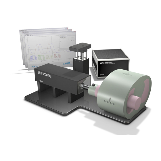
- Page 1 Dynamic Phantoms Model 008A, 008A-20,18023-A, 18043-A IMAGE ACQUISITION • TREATMENT PLANNING • DOSE DELIVERY USER GUIDE 900 Asbury Ave • Norfolk, Virginia 23513 • USA • Tel: 757-855-2765 • WWW.CIRSINC.COM...
-
Page 2: Table Of Contents
. . . . . . . . . . . 10 CIRS Motion Control Software . . . . . . . . . . . . . -
Page 3: Overview
CIRS Motion Control Software. The graphical user in- terface provides an unlimited variety of motions while the key differences between the Model 18023-A and the CIRS Model 008A include the length of phantom body, location of the moving rod within the lung, and the inclusion of ribs. -
Page 4: Safety
Safety GENERAL SAFETY NOTICE Warnings and Cautions are identified throughout this user guide to alert users of dangerous conditions that are created when instructions are not followed. Operation and maintenance personnel must observe all safety regulations. For the purposes of this manual, cautions are identified as situations that can cause damage to the phantom and internal electronics. -
Page 5: Unpacking Instructions
Unpacking Instructions Model 008A, 18023-A and 18043-A Pull phantom body from case. Before you open the case check the Remove wall partition from the case and three Drop ‘N’ Tell indicators on the set aside. right side of the case. Drop ‘N’... -
Page 6: Model 008A, 18023-A & 18043-A Assembly Procedure
Model 008A, 18023-A & 18043-A Assembly Procedure CAUTION: PHANTOM ASSEMBLY REQUIRES 2 PEOPLE. ONE PERSON FOR STABILIZING AND A SECOND FOR ASSEMBLING THE PHANTOM. FAILURE TO STABILIZE THE BASE PLATE CAN RESULT IN DAMAGE TO THE PHANTOM. Position phantom body on base plate as Place one screw through bottom of base Place base plate with actuator assembly shown. -
Page 7: Removal Of Ball Cube
Removal of Ball Cube Insert (Optional) CIRS has provided a Ball Cube Removal Tool. Please note precautions on Ball Cube insert packaging. Gently push forward until Ball Cube is removed. Do not use Insert Ball Cube Removal Tool into back of Target Moving Rod other tools for this purpose as they may damage the surface of at insertion point as shown above. -
Page 8: Model 008A, 18023-A & 18043-A Cables And Connections
Model 008A, 18023-A & 18043-A Cables and Connections WARNING: FOLLOW THE CABLE CONNECTION STEPS AS THEY ARE PRESENTED IN THIS USER GUIDE. CONNECTING THE CABLES WITH THE CONTROLLER “POWER ON” CAN SERIOUSLY DAMAGE THE PHANTOM’S ELECTRONICS. Attach ethernet cable to back of Plug the Cable DB25 m/m to back of Plug the Cable DB9 m/m which controller and to back of actuator. -
Page 9: Ct Qa Insert Set Up
1 mm in diameter, misalignments as shapes during different breathing mo- small as 0.5 mm can be easily visualized. tions, including patient-specific motion CIRS Motion Software Advanced Motion Param- The software measurement tool allows profiles. precise evaluation of these misalign- ments. -
Page 10: An Ethernet Connection
“Install Driver”. Adapter” folder found on the provided USB drive or download the zipped folder from the CIRS website. Archive to a known location and select autorun. Note: The provided “USB to Network Adapter” can act as Plug and Play device on some PC but CIRS recommends doing the installation of the driver as outlined above. - Page 11 Select Internet Protocol Version 4 (TCP/IPv4) and click on prop- Providing that the installation of the “USB-to-Network Card” erties was successful, the newly installed Network Adapter should show as “ASIX AX88179 USB 3.0 to Gigabit Ethernet Adapter”. Select it’s Properties using the right mouse click menu as shown below.
-
Page 12: Cirs Motion Control Software
If the end-user is offline during use of the phantom, it is recom- INTRODUCTION mended that a copy of the CIRS Motion Control User Manual is CIRS Motion Control is an application which allows you to control downloaded and saved. Once a copy of the manual is saved in a... -
Page 13: Model 008A Specifications
Note: Customers must complete their order with the purchase of at least one Part No. Component Description (1) interchangeable insert option. *Refer to separate CIRS cavity and plug code list for available chamber cavities. 008A Dynamic Thorax Phantom Body with 3D spine (Dosimeter &... -
Page 14: Warranty
Phantom and accessories CIRS not to comply with documented order specifications. You must return the product to CIRS within 30 calendar days of the issu- ance of the RMA. All returns should be packed in the original cases There are no warranties, expressed or implied, including without... -
Page 15: Notes
NOTES:... - Page 16 COMPUTERIZED IMAGING REFERENCE SYSTEMS, INC. 900 Asbury Ave Norfolk, Virginia 23513 USA Toll Free: 800.617.1177 Tel: 757.855.2765 Fax: 757.857.0523 Email admin@cirsinc.com www .cirsinc .com Technical Assistance 1.800.617.1177 ©2013 Computerized Imaging Reference Systems, Inc. All rights Computerized Imaging Reference Systems, Inc. has been certified by UL DQS Inc.
Need help?
Do you have a question about the Dynamic Phantoms 008A and is the answer not in the manual?
Questions and answers