Table of Contents
Advertisement
Advertisement
Table of Contents

Related Manuals for Tesmec DLR300


Summary of Contents for Tesmec DLR300
- Page 1 P P UL L L R DLR3 English...
- Page 3 PULL CORD del: D DLR3 rial n …… …… ……… …. ear of f man nufac cture …… …… ……… …. der nu umbe …… …… ……… …. Alwa ays quote the Mode l, Year of manufactu ure and O Order numb ber when r requesting...
- Page 4 TESMEC S.p.A. reserves the right to make technical and constructive changes to the DLR300 without prior notice and if deemed necessary Page IV ...
- Page 5 GENERAL INDEX Page GENERAL INDEX GENERAL INFORMATION AND REQUIREMENTS MANUFACTURER TYPE AND FIELD OF USE PARTS GUIDE 2.3.1 UPPER PANEL 2.3.2 REAR PANEL 2.3.3 STANDARD ACCESSORIES ...
-
Page 6: Firmware Update
ERROR 6 – SPAN PULL ERROR ERROR 7 – FULL SCALE ERROR FIRMWARE UPDATE INSTALLATION GUIDE OF THE BOOTLOADER DLR300 6.1.1 MINIMUM SYSTEM REQUIREMENTS 6.1.2 INSTALLING THE USB DRIVERS ... -
Page 7: General Information And Requirements
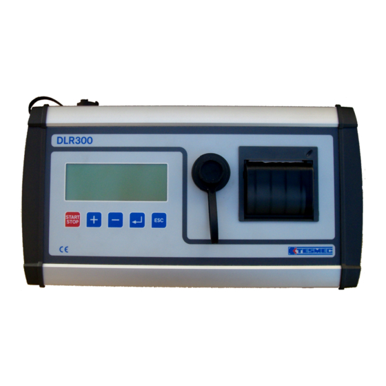
The DLR300 can record and save the data of individual cable stringing or laying operations in its internal memory. The saved data can be recalled at a later stage to be printed or exported to a USB flash device. - Page 8 PARTS GUIDE 2.3.1 UPPER PANEL DISPLAY: Backlit LCD with 8 rows of 24 characters each. TYPE-A USB FLASH SOCKET PRINTER: Thermal, which allows the real time cable laying data to be printed or recalled from the internal memory of the recorder. FUNCTION BUTTONS: These are the controls that provide access to the recording programme and the management menus of the cable stringing or laying operations: START/STOP BUTTON: Press this button twice to start or stop the pull recording...
-
Page 9: Rear Panel
STANDARD ACCESSORIES BOX: to transport the DLR300 WIRE: to connect the DLR300 PLUG: multi-voltage plug USB FLASH DRIVE TRANSPARENT POCKET: to protect the DLR300 in case of rain PAPER ROLL: to print the cable laying operations Page 3 ... -
Page 10: Internal Memory
INTERNAL MEMORY The inte ernal memory y of the DLR3 300 can save e 64 cable la aying operati ons, each on ne with 4,096 rows of information t that are print ted on paper The "cable la aying operat tion"... -
Page 11: Using The Recorder
USING THE RECORDER POSITIONING AND CONNECTING TO THE MACHINE Connect the DLR300 to the machine that is to be monitored, using the wire supplied together with the recorder. Implement the electrical connections between the recording unit and the machine with the engine switched off so as to prevent interference with the instruments. - Page 12 ATTENTION: press the button to activate or deactivate the screen light. ATTENTION: if the machine is used at low temperatures, the sensor and the pull recorder must be connected and electrically switched on for approx. 15 min before implementing any operation. The various functions can then be accessed via the keyboard.
-
Page 13: Setting The Limit Value
ATTENTION: the values range from 1.0 to the pre-set value in the MAX ROPE DIAM. (mm) item (refer to Chap 4.1.2.2). Press: to confirm the selection and move on to the next work parameter Press: to return to the main menu without saving any changes made. 3.4.2 SETTING THE SAMPLING ♦... - Page 14 3.4.6 SETTING THE LANGUAGE ♦ Select: LANGUAGE: English (or any other language available) Press: until the desired language is selected. All the screens displayed and printouts will be in the selected language. Press: to confirm the selection and return to the main menu Press: to return to the main menu without saving any changes made.
-
Page 15: Setting The Year
3.5.4 SETTING THE YEAR ♦ Select: Year: yy Press: to select the correct year. Press: to confirm the selection and move on to the next setting Press: to return to the main menu without saving any changes made. 3.5.5 SETTING THE HOURS ♦... - Page 16 BEGINNING AND END OF THE MONITORING PROCESS To begin the monitoring process, when the current date and time appear on the display: Press: twice and fast The following screen appears on the display, which corresponds to the data recording mode of the instrument: Fm: xxxx XXXX...
- Page 17 This s data is sav ved by the i instrument a and can be printed in re eal time or a at a later sta age. The print tout will be s similar to the example bel low: ere: serial nu umber of the pull recorde compan...
-
Page 18: Full Memory
The instrument saves 64 cable laying operations and when this value is reached, the DLR300 will write the subsequent operations restarting from the first, overwriting the data saved previously. It is therefore recommended to print or download the saved cable laying operations on a daily basis, deleting them from the memory so as to prevent unpleasant management problems. -
Page 19: View Recording
3.9.1 DISPLAY CABLE LAYING OPERATIONS Press: to navigate the cable laying management menu and select the DISPLAY RECORDING function ♦ Select: VIEW RECORDING Press: to access the display page of the recorded cable laying operations The following appears: VIEW RECORDING N:xx dd.mm.yy. - Page 20 The prin nter will provi de a similar graph to tha t shown belo The me tres covered d are shown n on the hor rizontal axis of the grap ph; a continu uous vertical l line indicates s the position ns in which a an inverted d direction occu...
-
Page 21: Please Wait
To stop the saving operations Press: to return to the cable laying management page. Once the saving process is complete, the device will communicate whether this has been completed successfully: The following appears: SAVING COMPLETE THE PEN DRIVE CAN BE REMOVED After removing the USB stick: Press: to return to the cable laying management page. - Page 22 3.9.5 DELETING AN INDIVIDUAL CABLE LAYING PROCESS Press: to navigate the cable laying management menu and select the DELETE RECORDING function ♦ Select: DELETE RECORDING Press: to access the page so as to delete the cable laying operations The following appears: DELETE RECORDING No:xx dd.mm.yy.
-
Page 23: Replacing The Paper Roll
3.10 REPLACING THE PAPER ROLL. When the feed button of the printer blinks, replace the roll of thermal paper. The printer will continue the print job once the paper is replaced and the feed button stops blinking. Proceed as follows to replace the roll: •... - Page 24 ATTEN TION! All t he foll lowing instru uctions s in the e man ual ref progr rammin setting alibrati oper rations s perfo ormed by t he ma anufac cturer. thes se are applie d inco rrectly y, they can ca ause t reco...
- Page 25 COMPANY NAME Press: to access the company name setting page The following appears: COMPANY SETTING - C TESMEC - ITALY (or another pre-set company name) Press: to select the individual character to be changed Press: to select the correct character until the desired text is...
- Page 26 The following appears: CAPSTAN DIAM (mm): MAX. ROPE DIAM (mm): CAPSTAN TEETH: ENCODER TEETH: ENCODER PULSES: 4.1.2.1 SETTING THE CAPSTAN DIAMETER ♦ Select: CAPSTAN DIAM (mm): 1200 (or another pre-set value) represents the bottom groove of the capstan expressed in mm. Press: until the desired value is selected ATTENTION: the values range from 1 to 2500 mm.
- Page 27 4.1.2.5 SETTING THE NUMBER OF ENCODER PULSES ♦ Select: ENCODER PULSES: 100 (or another pre-set value) represents the number of pulses per revolution transmitted by the encoder Press: until the desired value is selected ATTENTION: the values range from 1 to 1000 Press: to confirm the selection and return to the machine parameter edit menu...
-
Page 28: Setting The Sampling Frequency
Press: until the desired value is selected ATTENTION: the values range from 0 to 100 daN Press: to confirm the selection and move on to the next parameter Press: to return to the menu without saving any changes made 4.1.3.4 SETTING THE ADC FILTER ♦... -
Page 29: Setting The Functional Parameters
4.1.4 SETTING THE FUNCTIONAL PARAMETERS Press: to navigate the menu and select the FUNCTIONAL PARAMETERS function ♦ Select: FUNCTIONAL PARAMETERS Press: to access the settings page of the functional parameters The following appears: PULL RESOL. (daN): METHOD: USE: / POSIT. DIRECTION: 4.1.4.1 SETTING THE PULL VARIATION ♦... - Page 30 menu Press: to return to the menu without saving any changes made 4.1.4.4 SETTING THE POSITIVE DIRECTION ♦ Select: POSIT. DIRECTION: Puller (or Tensioner). Enter the mode to be set for positive stringing operations. ATTENTION: this parameter is only available if BIDIRECTIONAL mode was selected in the previous step Press: to select Tensioner...
- Page 31 4.1.5.2 PULLER CALIBRATION Press: to navigate the menu and select the PULLER CALIBRATION function ♦ Select: PULLER CALIBRATION Press: to access the puller calibration page The following appears: NORMAL PULLER CALIBRATION LINEARIS. STEPS: 1 (or another pre-set value). This value corresponds to the number of calibration steps required on the puller scale.
- Page 32 This value corresponds to the number of calibration steps required on the tensioner scale. Generally, it is recommended to perform at least four calibration steps, one of which as close as possible to the intended max. pull machine others intermediate values. Obviously, more calibration steps lead to greater instrument capacity to follow and reproduce the machine's behaviour Press:...
- Page 33 following is an example of a printout first value a acquired alwa ays refers to o zero and th he subseque ent are the in ndividual line earisation step ps implement ted, in ascen nding order. 4.1.6 SETTIN G THE SER IAL NUMBE Press: to navigate...
- Page 34 This lets the user upload the instrument configuration and calibration data previously saved on a USB stick on to the DLR300. Therefore, the same instrument can be used on various machines by simply uploading the saved data of the specific configuration of that machine.
-
Page 35: Print Configuration
stick Allows the user to transfer the instrument configuration and calibration data on to a USB stick, thereby making it available for recovery operations to be implemented on the instrument in the future The following appears: INSERT THE PEN DRIVE Insert the USB stick into the relative slot found on the upper panel of the instrument and Press: to start the saving operation... - Page 36 The follo owing is an e example of a printout: where: erial number ompany nam igital parame eters nalogue para ameters unctional par rameters Work paramet ters ero-bit Machine calib ration tables Page 30 ...
-
Page 37: Restoring The Default Configuration
The following appears: LOAD A LANGUAGE Waiting for connection.. Connect the recorder to a personal computer that has the firmware management programme installed and proceed as described in paragraph 6.2, DLR300 BOOTLOADER USER GUIDE 4.2.5 RESTORING THE DEFAULT CONFIGURATION Press:... - Page 38 MANAGING ERRORS ERROR 1 – CHECK GENERAL PARAMETERS The following appears: ERR.1: CHECK GENERAL PARAMETERS This indicates the programmes have been deleted from the instrument memory. ⇒ Verify that all the data is programmed correctly, relative to the parameters of use as well as the constants and calibrations.
- Page 39 USB DRIVER Follo ow the instru uctions below w to install th e USB driver 1. Insert th he “Bootloade er DLR300” C CD in the CD D-ROM; 2. Access t the CD-ROM M from My Co omputer (com mputer mana agement soft tware);...
- Page 40 Access “x:\U USB DRIVER R”, where x is s the letter of f the CD-RO Double click k the executa able file in the e folder to sta art installing the drivers; Authorise th e installation n when the U User Account t Control wind dow appears...
-
Page 41: Instal Ling The S
6.1.3 INSTAL LING THE S SOFTWARE Follo ow the instru uctions below w to install th e firmware u update softwa are: 1. Access “x:\BOOTLO OADER DLR3 300”, where x is the lette r of the CD-R ROM; 2. Double c click the setu up_btl_dlr300 0 file in the fo... - Page 42 Click Ins stall to proce eed; The DLR300 0 Bootloader r Installation window appe ears. Click Contin ue to procee ed or Quit to exit the insta allation. Page 36 ...
- Page 43 6. Enter th he folder pat h manually o or click Brow wse to selec ct where the programme e is to be installed Click Ne ext to procee ed or Quit to e exit the insta allation: 7. Specify the User for whom the p programme is...
- Page 44 Click Finish to complete the process Connect the e DLR300 to o the USB p port of the P PC in order to complete e the install ation correctly. Use the type...
-
Page 45: Software Functions
This can be done by the end user, without sending the DLR300 to the manufacturer. The option of adding a new language must be used to download new messages to the DLR300 memory. Normally, the DLR300 allows the user to select a language from ITALIAN, ENGLISH and SPANISH. - Page 46 3. A dialog gue window a appears: info orming the us ser to conne ct and switch h on the DLR R300 and to N NEVER switc ch the device e off during th he firmware u update; 4. The upd date prepara ation window appears.
- Page 47 2. Click Se elect FIRMWA WARE file and d select the .H HEX file of th he firmware; 3. Click the e START DO OWNLOAD b button to star rt the update ; a blue bar d displays the progress of the pr rocedure;...
- Page 48 K to finish. Close the Bo ootloader an d switch the DLR300 off; Disconnect t the USB that t connects th he DLR300 to o the PC ATTENTION : If multiple DLR300 un nits are to be e updated, t the Bootloa...
-
Page 49: Spare Parts
V00-8700-007 : Wire L=10m □ V00-8700-040 : Wire L=0.5m □ V00-8400-035 : Plug □ V00-8700-039 : 2 GB USB stick □ V00-2228-012 : Transparent pocket □ V00-8700-041 : Thermal paper roll □ MI-DLR300 : Manual Page 43 ... - Page 52 24050 Grassobbio (BG) Via Zanica 17/O 24060 Endine Gaiaiano (BG) Via Pertegalli Tel. +39 035 4232911 – Fax +39 035 4522445 Tel. +39 035 825024 - Fax +39 035 826375 www.tesmec.it – info@tesmec.it www.tesmec.it – info@tesmec.it Literature Part No. 21009805 Revision No. 1.0...
Need help?
Do you have a question about the DLR300 and is the answer not in the manual?
Questions and answers