Cabletron Systems SmartSwitch 6000 Installation & User Manual
Smartswitch 6000 interface modules
Hide thumbs
Also See for SmartSwitch 6000:
- User manual (420 pages) ,
- Installation & user manual (74 pages) ,
- Management manual (46 pages)

Related Manuals for Cabletron Systems SmartSwitch 6000


Summary of Contents for Cabletron Systems SmartSwitch 6000
- Page 1 6H202-24, 6H252-17, and 6H262-18 SmartSwitch 6000 Interface Modules Installation User’s Guide 9033378...
- Page 3 Only qualified personnel should perform installation procedures. NOTICE Cabletron Systems reserves the right to make changes in specifications and other information contained in this document without prior notice. The reader should in all cases consult Cabletron Systems to determine whether any such changes have been made.
-
Page 4: Fcc Notice
FCC NOTICE This device complies with Part 15 of the FCC rules. Operation is subject to the following two conditions: (1) this device may not cause harmful interference, and (2) this device must accept any interference received, including interference that may cause undesired operation. -
Page 5: Program License Agreement
PROGRAM LICENSE AGREEMENT IMPORTANT:THIS LICENSE APPLIES FOR USE OF PRODUCT IN THE FOLLOWING GEOGRAPHICAL REGIONS: CANADA MEXICO CENTRAL AMERICA SOUTH AMERICA BEFORE OPENING OR UTILIZING THE ENCLOSED PRODUCT, CAREFULLY READ THIS LICENSE AGREEMENT. This document is an agreement (“Agreement”) between You, the end user, and Cabletron Systems, Inc. (“Cabletron”) that sets forth your rights and obligations with respect to the Cabletron software program (“Program”) in the package. - Page 6 If the Program is exported from the United States pursuant to the License Exception TSR under the U.S. Export Administration Regulations, in addition to the restriction on transfer set forth in Sections 1 or 2 of this Agreement, You agree not to (i) reexport or release the Program, the source code for the Program or technology to a national of a country in Country Groups D:1 or E:2 (Albania, Armenia, Azerbaijan, Belarus, Bulgaria, Cambodia, Cuba, Estonia, Georgia, Iraq, Kazakhstan, Kyrgyzstan, Laos, Latvia, Libya, Lithuania, Moldova, North Korea, the People’s Republic of China, Romania, Russia, Rwanda, Tajikistan, Turkmenistan, Ukraine, Uzbekistan, Vietnam, or such other countries as may be...
- Page 7 CABLETRON SYSTEMS SALES AND SERVICE, INC. PROGRAM LICENSE AGREEMENT IMPORTANT: THIS LICENSE APPLIES FOR USE OF PRODUCT IN THE UNITED STATES OF AMERICA AND BY UNITED STATES OF AMERICA GOVERNMENT END USERS. BEFORE OPENING OR UTILIZING THE ENCLOSED PRODUCT, CAREFULLY READ THIS LICENSE AGREEMENT.
- Page 8 UNITED STATES GOVERNMENT RESTRICTED RIGHTS. The enclosed Product (i) was developed solely at private expense; (ii) contains “restricted computer software” submitted with restricted rights in accordance with section 52.227-19 (a) through (d) of the Commercial Computer Software-Restricted Rights Clause and its successors, and (iii) in all respects is proprietary data belonging to Cabletron and/or its suppliers.
- Page 9 PROGRAM LICENSE AGREEMENT IMPORTANT: THIS LICENSE APPLIES FOR THE USE OF THE PRODUCT IN THE FOLLOWING GEOGRAPHICAL REGIONS: EUROPE MIDDLE EAST AFRICA ASIA AUSTRALIA PACIFIC RIM BEFORE OPENING OR UTILIZING THE ENCLOSED PRODUCT, CAREFULLY READ THIS LICENSE AGREEMENT. This document is an agreement (“Agreement”) between You, the end user, and Cabletron Systems Limited (“Cabletron”) that sets forth your rights and obligations with respect to the Cabletron software program (“Program”) in the package.
- Page 10 If the Program is exported from the United States pursuant to the License Exception TSR under the U.S. Export Administration Regulations, in addition to the restriction on transfer set forth in Sections 1 or 2 of this Agreement, You agree not to (i) reexport or release the Program, the source code for the Program or technology to a national of a country in Country Groups D:1 or E:2 (Albania, Armenia, Azerbaijan, Belarus, Bulgaria, Cambodia, Cuba, Estonia, Georgia, Iraq, Kazakhstan, Kyrgyzstan, Laos, Latvia, Libya, Lithuania, Moldova, North Korea, the People’s Republic of China, Romania, Russia, Rwanda, Tajikistan, Turkmenistan, Ukraine, Uzbekistan, Vietnam, or such other countries as may be...
- Page 11 THE GPIM-01 AND GPIM-09 GIGABIT ETHERNET MODULES READ THE FOLLOWING SAFETY INFORMATION BEFORE INSTALLING OR OPERATING The Class 1 laser transceivers use an optical feedback loop to maintain Class 1 operation limits. This control loop eliminates the need for maintenance checks or adjustments. The output is factory set, and does not allow any user adjustment.
- Page 12 Application of Council Directive(s): 89/336/EEC Manufacturer’s Name: Cabletron Systems, Inc. Manufacturer’s Address: European Representative Name: Mr. J. Solari European Representative Address: Conformance to Directive(s)/Product Standards: Equipment Type/Environment: Networking Equipment, for use in a Commercial We the undersigned, hereby declare, under our sole responsibility, that the equipment packaged with this notice conforms to the above directives.
-
Page 13: Table Of Contents
Broadcast Suppression ... 1-5 1.1.8 Port/VLAN Redirect Functions ... 1-5 1.1.9 Rate Limiting ... 1-5 1.1.10 GARP Switch Operation... 1-6 1.1.11 Flow Control ... 1-6 1.1.12 802.1 Port Priority ... 1-6 1.1.13 Management ... 1-7 1.1.14 Switching Options ... 1-7 1.1.15 Distributed Chassis Management ... - Page 14 3.7.2 Connecting the GPIM... 3-12 Completing the Installation... 3-14 TROUBLESHOOTING Using LANVIEW... 4-1 4.1.1 The LED Mode Switch ... 4-2 GPIM LED Descriptions for the 6H262-18 ... 4-6 Redundancy ... 4-7 Troubleshooting Checklist... 4-8 Using the RESET Button... 4-12 SPECIFICATIONS Module Specifications ...A-1...
- Page 15 B.1.1 GPIM-01 Specifications (1000Base-SX) ...B-1 B.1.2 GPIM-09 Specifications (1000Base-LX) ...B-2 Physical and Environmental Specifications...B-2 Regulatory Compliance...B-3 SWITCH SETTINGS, UPGRADES, AND INSTALLATIONS Setting the Mode Switches... C-1 SIMM Upgrade ... C-3 C.2.1 Locating SIMMs ... C-3 C.2.2 Installing the DRAM SIMM ... C-4 Installing Optional High Speed Interface Modules ...
-
Page 16: Figures
6H262-18 with Two Fiber Optic GPIM Ports ... 3-14 LANVIEW LEDs ... 4-3 LANVIEW LEDs for the GPIM ... 4-6 Reset Button... 4-12 Module Mode Switch Location/Component Layout ... C-2 SIMM Slot Locations ... C-3 Installing the DRAM... C-4 HSIM and VHSIM Connector Locations ... C-5... - Page 17 Table GPIM Options ... 1-8 Contents of Shipping Container ... 3-2 LANVIEW LEDs for the Module ... 4-4 Speed and Full Duplex LED Indications ... 4-5 GPIM LED Functionality... 4-7 Fault Identification ... 4-8 Power System Troubleshooting ... 4-9 Firmware Troubleshooting ... 4-10 Management System Troubleshooting ...
-
Page 19: Using This Guide
Welcome to the Cabletron Systems 6H202-24, 6H252-17, and 6H262-18 SmartSwitch 6000 Interface Modules Installation User’s Guide. This guide describes the SmartSwitch Interface Modules and provides information concerning network requirements, installation, and troubleshooting. For information about how to use Local Management to configure and manage the SmartSwitch series, refer to the SmartSwitch Series 6H202, 6H203, 6H252, 6H253, 6H258, 6H259, 6H262, 6E233, and 6E253 Local Management User’s Guide. -
Page 20: Structure Of This Guide
1, Introduction, describes the features of the SmartSwitches. Chapter Network Requirements, outlines the network requirements that must be met before installing the SmartSwitches into the 6C105 SmartSwitch 6000 chassis. Chapter 3, Installation, provides instructions on how to install a module in the chassis and connect segments. -
Page 21: Related Manuals
The following manuals may help the user to set up and manage the SmartSwitch modules: • SmartSwitch Series 6H202, 6H203, 6H252, 6H253, 6H258, 6H259, 6H262, 6E233, and 6E253 Local Management User’s Guide • 6C105 SmartSwitch 6000 Overview and Setup Guide • Ethernet Technology Guide • Cabling Guide •... -
Page 22: Document Conventions
Document Conventions DOCUMENT CONVENTIONS The following conventions are used throughout this document: Note symbol. Calls the reader’s attention to any item of information that may be of NOTE special importance. Tip symbol. Conveys helpful hints concerning procedures or actions. Caution symbol. Contains information essential to avoid damage to the equipment. CAUTION Electrical Hazard Warning symbol. -
Page 23: Introduction
Introduction This chapter introduces the 6H202-24, 6H252-17, and 6H262-18 SmartSwitch 6000 interface modules and provides information about how to obtain additional support from Cabletron Systems. Important Notice Depending on the firmware version used in the SmartSwitches, some features described in this document may not be supported. -
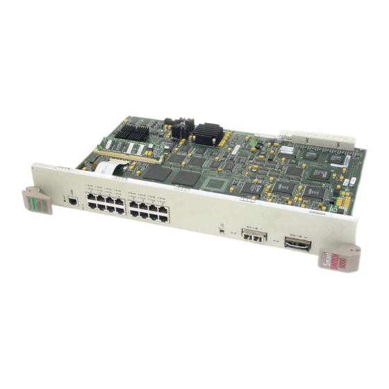
Page 24: The 6H202-24, 6H252-17, And 6H262-18 Smartswitches
Overview Figure 1-1 The 6H202-24, 6H252-17, and 6H262-18 SmartSwitches Introduction... -
Page 25: Connectivity
1.1.1 Connectivity The SmartSwitch modules connect to Ethernet networks or workstations through the RJ45 ports on the front panel. These ports are IEEE 802.3 10BASE-T and IEEE 802.3u 100BASE-TX compliant. The ports support Category 5 Unshielded Twisted Pair cables with an impedance between 85 and 111 ohms at lengths up to 100 meters for both 10 Mbps and 100 Mbps Ethernet connections. -
Page 26: Full Duplex Switched Ethernet
Overview The RAD requests start at an interval of one per second. The interval then doubles after every transmission until an interval of 300 seconds is reached. At this point, the interval remains at 300 seconds. The RAD requests continue until an IP address is received from a RARP or BootP server, or an IP address is entered using Local Management. -
Page 27: Broadcast Suppression
VLAN classification of the frames received. The VLAN redirect function does not support redirecting errors, and is only supported when the device is operating as an 802.1Q switch. Multiple VLANs can be directed to the same ports. -
Page 28: Garp Switch Operation
GARP attributes such as VLAN and multicast group membership. For more details on how GVRP and GMRP handle frames under GARP, and how to configure the switch ports to take advantage of this operation, refer to the SmartSwitch Series 6H202, 6H203, 6H252, 6H253, 6H258, 6H259, 6H262, 6E233, and 6E253 Local Management User’s Guide. -
Page 29: Management
1.1.15 Distributed Chassis Management From a management perspective, the 6C105 SmartSwitch 6000 chassis can be viewed as a single entity with a single IP address. Its systems management functions are distributed to all modules. -
Page 30: Optional Gpims
Overview 1.1.17 Optional GPIMs The 6H262-18 provides two slots for optional Gigabit Ethernet Modules (GPIMs) for connection to Gigabit Ethernet. 1000Base-SX is supported with the GPIM-01 providing one SC fiber optic connector for 50 or 62.5 micron multimode fiber optic cable. 1000Base-LX is supported with the GPIM-09 providing one SC fiber optic connector for 50 or 62.5 micron multimode fiber optic cable, or 10 micron single mode fiber optic cable. -
Page 31: Lanview Diagnostic Leds
1.1.19 LANVIEW Diagnostic LEDs LANVIEW diagnostic LEDs serve as an important troubleshooting aid by providing an easy way to observe the status of individual ports and overall network operations. 1.1.20 Year 2000 Compliance The SmartSwitch modules and the 6C105 chassis have an internal clock that maintains the time and date beyond the year 1999. -
Page 33: Network Requirements
Before installing the SmartSwitch modules, review the requirements and specifications referred to in this chapter concerning the following: • SmartTrunk (Section 2.1) • 10BASE-T Twisted Pair Network • 100BASE-TX Twisted Pair Network • 1000BASE-SX, -LX Gigabit Ethernet The network installation must meet the guidelines in this chapter and in the documents referenced in this chapter to ensure satisfactory performance of the equipment. -
Page 34: 100Base-Tx Network
100BASE-TX Network If a port is to operate at 100 Mbps, Category 5 cabling must be used. For 10 Mbps NOTE operation only, Category 3 cabling can be used. Refer to about 100BASE-TX networks and cabling. 100BASE-TX NETWORK The fixed front panel ports of the SmartSwitch provide an RJ45 connection that supports Category 5 UTP cabling. -
Page 35: Installation
Only qualified personnel should install the SmartSwitch modules. Read the Release Notes shipped with the device to check for any exceptions to the NOTE supported features and operation documented in this guide. This chapter covers the following items: • Unpacking the Module •... -
Page 36: Unpacking The Module
Unpacking the Module UNPACKING THE MODULE Open the box and remove the packing material protecting the module. Verify the contents of the carton as listed in Table 3-1 Contents of Shipping Container Item 1 module, either the 6H202-24, 6H252-17, or 6H262-18 Manual Accessory Kit INSTALLING HSIM OR VHSIM OPTIONS If installing an optional HSIM or VHSIM, it must be installed in the 6H252-17 before proceeding... - Page 37 Remove the blank panel covering the slot in which the module will be installed. All other slots must remain covered to ensure proper airflow and cooling. (Save the blank plate in the event you need to remove the module.) Carefully remove the module from the shipping box. (Save the box and packing materials in the event the module must be reshipped.) Locate the antistatic wrist strap shipped with the 6C105 chassis.
-
Page 38: Installing An Interface Module
Installing the Module into the 6C105 Chassis Figure 3-1 Installing an Interface Module Examine the module for damage. If any damage exists, DO NOT install the module. Immediately contact the Cabletron Systems. Refer to Section 1.2, for details. Installation... -
Page 39: Connecting To The Network
To prevent damaging the backplane connectors in the following step, take care that the module slides in straight and properly engages the backplane connectors. CAUTION Ensure that the top plastic locking tab lines up with the desired slot number located on the front panel of the chassis. Refer to Locate the slot guides that line up with the number of the slot in which the module will be installed. -
Page 40: Connecting A Twisted Pair Segment To The Smartswitch
If the RX LED is OFF and the TX (Transmit) LED is not blinking amber, perform the following steps until it is on: Verify that the LED mode switch located near the COM port of the module is in the UP position (RX and TX LED indicators). -
Page 41: Straight-Through Cable Rj45 Pinouts
Verify that the RJ45 connectors on the twisted pair segment have the proper pinouts (Figure 3-3 Figure is used between a switching or hub device and an end user (computer). A straight-through cable is used between hub devices. Figure 3-3 Crossover Cable RJ45 Pinouts Figure 3-4 Straight-Through Cable RJ45 Pinouts Ensure that the twisted pair connection meets the dB loss and cable specifications outlined in the Cabletron Systems Cabling Guide. -
Page 42: Installing Gpims
Installing GPIMs INSTALLING GPIMS The 6H262-18 has two different GPIMs that can be installed. Both GPIMs are installed using the same method, as shown in this procedure. The GPIMs are hot swappable, therefore they can be installed into the 6H262-18 at any NOTE time during the installation of the module. -
Page 43: Installing A Gpim Into The 6H262-18
Gently insert the GPIM (20-pin connector side) through the GPIM opening of the 6H262-18. Figure 3-6. The door folds in and the slides engage the sides of the GPIM. If the GPIM does not go in easily, do not force the device. Check the orientation against GPIM back until the 20-pin port engages the GPIM. -
Page 44: Gpim Network Connections
GPIM Network Connections GPIM NETWORK CONNECTIONS The GPIM-01 and the GPIM-09 each have an SC style connector for the network port that is used to connect to the Gigabit Ethernet network. Cabletron Systems offers fiber optic cables that use SC style connectors which are keyed to ensure proper crossover of the transmit and receive fibers. -
Page 45: Gpim-09 Connection Using Multimode Cable
specifications in the Appendix B, network. An odd number of crossovers (preferably one) must be maintained between like devices NOTES so that the transmit port of one device is connected to the receive port of the other device and vice versa. If the fiber optic cable being used has SC style connectors that do not resemble MIC style connectors, or has SC connectors on one end and a different type on the other, such as ST connectors, ensure that the proper cable cross-over occurs. -
Page 46: Connecting The Gpim
GPIM Network Connections 3.7.2 Connecting the GPIM To connect the GPIM using fiber optic cable to the network, perform the following steps: If connecting the GPIM-09 to the network using multimode fiber optic cable, refer to NOTE Section 3.7.1 before following this procedure. Remove the protective covers from the fiber optic ports and from the ends of the connectors. -
Page 47: Fiber Optic Gpim Connections
Figure 3-9 Fiber Optic GPIM Connections At the other end of the fiber optic cable, attach the SC connector to the other device. Verify that a link exists by checking that the port Receive LED is ON (flashing amber, blinking green, or solid green) for the GPIM. -
Page 48: Completing The Installation
Completing the Installation To remove the SC connector from the GPIM, carefully pull the connector out of the port. It may need to be wiggled gently to release the latching keys. Figure 3-10 6H262-18 with Two Fiber Optic GPIM Ports If a link has not been established, refer to Chapter 4 to use the LEDs for troubleshooting before... -
Page 49: Troubleshooting
This chapter provides information concerning the following: • Using the LANVIEW diagnostic and status monitoring system • Troubleshooting network and module operational problems • Using the RESET button USING LANVIEW The SmartSwitch modules use Cabletron Systems’ built-in visual diagnostic and status monitoring system called LANVIEW. -
Page 50: The Led Mode Switch
When the switch is in the UP position, the LEDs indicate the receive (RX) and transmit (TX) status of the fixed ports. When the mode switch is in the DOWN position, the LEDs indicate at what speed the applicable port is currently operating (10 Mbps or 100 Mbps) and if the applicable port is operating in standard or full duplex mode. -
Page 51: Lanview Leds
Using LANVIEW Figure 4-1 LANVIEW LEDs Troubleshooting... -
Page 52: Lanview Leds For The Module
Booting. Blinks amber and and Green green while booting. The following port RX and TX LED indications are only valid when the LED MODE switch is in the RX-TX position. No link. No activity or port in Standby. Port enabled or disabled. -
Page 53: Speed And Full Duplex Led Indications
Solid. Diagnostic Failure. Table 4-2 Speed and Full Duplex LED Indications Color The following port DPX and SPD LED indications are only valid when the LED MODE switch is in the DPX-SPD position. Amber (Duplex Status) Green Amber... -
Page 54: Gpim Led Descriptions For The 6H262-18
GPIM LED Descriptions for the 6H262-18 GPIM LED DESCRIPTIONS FOR THE 6H262-18 Figure 4-2 LANVIEW LEDs for the GPIM Troubleshooting... -
Page 55: Redundancy
Green (Solid) Green (Blinking) Receive Amber (Flashing) When the LED MODE switch is in the DPX-SPD position, both the RX and TX LEDs will NOTE be on solid green to indicate full duplex Gigabit speed. REDUNDANCY The 6H262-18 supports redundancy between the GPIM ports. Only one of the two GPIM ports on the 6H262-18 is active at one time. -
Page 56: Troubleshooting Checklist
Troubleshooting Checklist TROUBLESHOOTING CHECKLIST If the module is not working properly, refer to causes, and recommended actions to resolve the problem. Symptom All LEDs off. Module stays in BOOT state. Cannot access Local Management. Cannot contact device through in-band management. User parameters (IP address, community names, etc.) lost on reset or power-up. -
Page 57: Power System Troubleshooting
Table 4-5 Power System Troubleshooting Possible Causes Loss of Power to the 6C105 chassis. Fault in 6C105 power bus. Fault in module power converter. Instruction Perform the following steps: 1. Check ON/OFF switches of 6C105 power supplies. All switches must be in the ON ( | ) position. 2. -
Page 58: Management System Troubleshooting
Troubleshooting Checklist Possible Causes Autobaud enabled. Terminal setup is not correct. Improper console cable pinouts. The COM port of the device has been disabled, or the COM port application has been changed. Corrupt firmware image, or hardware fault. Table 4-7 Management System Troubleshooting Possible Causes Improper Community Names T able. -
Page 59: Device Setup Troubleshooting
Table 4-8 Device Setup Troubleshooting Possible Causes The module detects a looped condition. Mode switch (7), NVRAM Reset, was changed sometime before either cycling power or pressing the RESET button, causing the user-entered parameters to reset to factory default settings. -
Page 60: Using The Reset Button
Using the RESET Button USING THE RESET BUTTON The RESET button, located near the upper plastic locking tab of the module (refer to resets the SmartSwitch processor without affecting the NVRAM. Pressing the RESET button resets the device, and all current switching being performed by the module is halted. -
Page 61: A.3 Environmental Requirements
This appendix provides operating specifications for the Cabletron Systems SmartSwitch Interface Modules. Cabletron Systems reserves the right to change these specifications at any time without notice. MODULE SPECIFICATIONS Processors: Dynamic Random Access Memory (DRAM): FLASH Memory: Shared Memory: PHYSICAL PROPERTIES Dimensions: Weight (Unit): MTBF (Predicted):... -
Page 62: Input/Output Ports
Input/Output Ports INPUT/OUTPUT PORTS 6H252-17 Specifications Ports 1 through 16: Slot for optional High Speed Interface Module (HSIM) or Very High Speed Interface Module (VHSIM): 6H202-24 Specifications Ports 1 through 24: 6H262-18 Specifications Ports 1 through 16: 2 slots for optional Gigabit (Ethernet) Port Interface Module (GPIM): Specifications Fast Ethernet 10/100 Mbps (100BASE-TX... -
Page 63: A.6 Regulatory Compliance
COM PORT PINOUT ASSIGNMENTS The COM port is a serial communications port that supports Local Management or connection to a UPS. Table A-1 shows the COM port pin assignments: Signal Name Transmit Data (XMT) Data Carrier Detect (DCD) Data Set Ready (DSR) Receive Data (RCV) Signal Ground (GND) Data Terminal Ready (DTR) -
Page 65: B-1 Gpim-01 Optical Specifications
This appendix lists the specifications and regulatory requirements for GPIMs and the media they use. Cabletron Systems reserves the right to change these specifications at any time without notice. The available GPIM options include the GPIM-01 and GPIM-09. The GPIM-01 and GPIM-09 are both fiber optic devices with an SC connector. -
Page 66: B-6 Gpim Environmental Requirements
Physical and Environmental Specifications B.1.2 GPIM-09 Specifications (1000Base-LX) Transmit Power (minimum) Receive Sensitivity Link Power Budget 62.5 µm MMF 50 µm MMF 50 µm MMF 10 µm SMF A. In order to obtain the distance of 550 m for the GPIM-09 using multimode fiber optic cable, Launch Mode Conditioning cable must be used. -
Page 67: B-7 Gpim Safety And Emc Requirements
REGULATORY COMPLIANCE The GPIMs meet the following safety and electromagnetic compatibility (EMC) requirements: Table B-7 GPIM Safety and EMC Requirements Eye Safety (fiber optic GPIMs only) Regulatory Compliance FDA CDRH 21-CFR 1040 Class 1, IEC 825 Issue 1 1993:11 Class 1, CENELEC EN 60825 Class 1, GPIM Specifications... -
Page 69: C.1 Setting The Mode Switches
Clear NVRAM and restore all user-entered parameters such as the IP address and Subnet Masks to the SmartSwitch “Default” configuration settings. • Clear user-entered passwords stored in NVRAM and restore the default passwords. Figure C-1 shows the location of the mode switches and the switch settings for normal operation. (Section C.1) (Section C.2) (Section C.3) -
Page 70: C-1 Module Mode Switch Location/Component Layout
Autobaud sensing and sets the COM port to 9600 baud for Local Management sessions. • Switch 6 – Forced BootP. Changing the position of this switch (i.e., moving the switch from one position to the other) clears download information from NVRAM and forces the SmartSwitch to download a new image file from a BootP server after power to the chassis is restored. -
Page 71: C-2 Simm Slot Locations
SmartSwitch resets, the passwords can either be reentered or the default passwords (Public and ENTER) may be used. Do not change the position of switch 8 unless it is necessary to reset the module NOTE super-user configured passwords to their factory default settings. -
Page 72: Installing The Dram Simm
Pivot the SIMM downward so the connector clips align with the two side notches of the SIMM and the connector clips lock the SIMM into place. Switch Settings, Upgrades, and Installations Figure C-3 and proceed as follows:... -
Page 73: C-4 Hsim And Vhsim Connector Locations
Depending on if an HSIM or VHSIM is installed, one or both connectors are used. Refer to the installation instructions for the optional HSIM or VHSIM in the associated NOTE user’s guide. Figure C-4 HSIM and VHSIM Connector Locations Installing Optional High Speed Interface Modules Switch Settings, Upgrades, and Installations... - Page 75 Installation connecting to the Network High Speed Interface Module Module Very High Speed Interface Module LANVIEW LEDs LDRAM installation Local Management introduction Memory upgrading Mode Switch Bank Settings NVRAM clearing Physical properties Port Redirect Function, introduction to Index Index-1...
- Page 76 Redirect functions port and VLAN, introduction to Regulatory Compliance A-3, Related Manuals RESET button 4-12 Runtime IP Address Discovery Safety Safety information laser SDRAM installation SIMMs installing LDRAM location SmartTrunk, introduction Specifications Standards compatibility Index-2 Troubleshooting checklist Unpacking VLAN Redirect Function, introduction to...
Need help?
Do you have a question about the SmartSwitch 6000 and is the answer not in the manual?
Questions and answers