Table of Contents
Advertisement
Advertisement
Table of Contents

Related Manuals for Ebyte E220-900T22D


Summary of Contents for Ebyte E220-900T22D
- Page 1 E220-900T22D User Manual 868/915MHz 22dBm LoRa Wireless Module...
-
Page 2: Table Of Contents
11. Soldering Operation Guidance..........................20 11.1 Reflow Soldering Temperature........................20 11.2 Reflow Soldering Curve..........................20 12. Related Models............................... 21 13. Antenna Recommendation............................21 13.1 Antenna Recommendation........................... 21 14. Package for Bulk Order............................22 Revision History................................22 About us..................................22 Copyright ©2012–2020,Chengdu Ebyte Electronic Technology Co., Ltd. - Page 3 Chengdu Yibaite Electronic Technology Co., Ltd. does not guarantee that the content of this manual is completely free of errors, and all statements, information and Suggestions in this manual do not constitute any express or implied warranty. Copyright ©2012–2020,Chengdu Ebyte Electronic Technology Co., Ltd.
-
Page 4: Overview
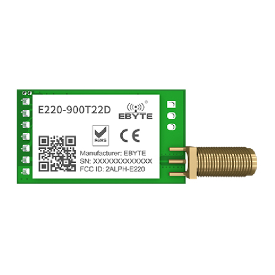
1. Overview 1.1 Introduction E220-900T22D adopts a new generation of LoRa spread spectrum technology and a wireless serial port module (UART) designed based on the LLCC68 chip scheme. It has a variety of transmission methods, works in the (850.125 ~ 930.125MHz) frequency band (default 873.125MHz), TTL level output, compatible with 3.3V and 5V IO port voltage. -
Page 5: Specification And Parameter
200 Byte 32/64/128/200 bytes per packet to transmit Buffer 400 Byte Modulation LoRa New generation LoRa modulation technology Communication interface UART Serial Port TTL Level Package Size 21*36mm Antenna SMA-K 50 ohm impedance Copyright ©2012–2020,Chengdu Ebyte Electronic Technology Co., Ltd. -
Page 6: Size And Pin Definition
MCU, and outputs low level during power-on self-check initialization; (can be left floating) Input Voltage range: 3.0~5.5V DC Input Ground Fixed hole Fixed hole Fixed hole Fixed hole Fixed hole Fixed hole Copyright ©2012–2020,Chengdu Ebyte Electronic Technology Co., Ltd. -
Page 7: Recommended Connection Diagram
The wireless serial port module is TTL level, please connect with TTL level MCU. For some 5V MCU, it may be necessary to add 4-10K pull-up resistors to the TXD and AUX pins of the module. Copyright ©2012–2020,Chengdu Ebyte Electronic Technology Co., Ltd. -
Page 8: Function Description
Chengdu Ebyte Electronic Technology Co., Ltd. E220-900T22D User Manual 5. Function Description 5.1 Fixed Transmission Figure 5-1 Fixed Transmission 5.2 Broadcasting Transmission Figure 5-2 Broadcasting Transmission Copyright ©2012–2020,Chengdu Ebyte Electronic Technology Co., Ltd. -
Page 9: Broadcasting Address
It can indicate whether there are data that are not sent yet via wireless way, or whether all wireless data has been sent through UART, or whether the module is still in the process of self-check initialization. 5.6.1 Indication of UART Output To wake up external MCU Figure 5-3 To wake up external MCU Copyright ©2012–2020,Chengdu Ebyte Electronic Technology Co., Ltd. - Page 10 [Note]: When AUX=1, it does not mean that all serial port data of the module has been transmitted wirelessly, and the last packet of data may be being transmitted. Figure 5-4 Transmitting indication 5.6.3 Configuration Procedure of Module Only happened when power-on resetting or exiting sleep mode Figure 5-5 Configuration mode Copyright ©2012–2020,Chengdu Ebyte Electronic Technology Co., Ltd.
-
Page 11: Operating Mode
Therefore, the general recommendation is to detect the output state of the AUX pin and switch after 2ms when the output is high. Copyright ©2012–2020,Chengdu Ebyte Electronic Technology Co., Ltd. -
Page 12: Normal Mode(Mode 0
It can receive data normally, the receiving function is the same as mode 0. 6.4 WOR receiving mode (Mode 2) Table 6-4 WOR receiving mode Type When M0 = 0, M1 = 1, the module works in mode 2 Copyright ©2012–2020,Chengdu Ebyte Electronic Technology Co., Ltd. -
Page 13: Deep Sleep (Configuration) Mode (Mode 3)
Example 2:Configure module address (0x1234), serial port (9600 8N1), air speed (2.4K) Send: C0 00 03 12 34 62 Return:C1 00 03 12 34 62 Command: C1+starting address+parameters Response: C1+starting address+length+parameters Example:Read channel Read Register command starting address length parameter Send: Return: Copyright ©2012–2020,Chengdu Ebyte Electronic Technology Co., Ltd. -
Page 14: Register Description
UART Rate is 115200 Serial Parity Bit 8N1(default) The serial port mode of the communication parties can be different; 8N1(equal to 00) Air Data Rate(bps) The air rate of both parties must be the same; Copyright ©2012–2020,Chengdu Ebyte Electronic Technology Co., Ltd. - Page 15 After enabling, monitoring will be conducted LBT Enable before wireless data transmission, which can Disable(default) avoid interference to a certain extent, but may cause data delay; Enable The maximum stay time of LBT is 2 seconds, and Copyright ©2012–2020,Chengdu Ebyte Electronic Technology Co., Ltd.
-
Page 16: Factory Default Parameter
7.3 Factory Default Parameter Table 7-3 Default parameters Model Factory default parameter:c0 00 00 62 00 17 Module No. Frequency Module No. Frequency Module No. Frequency Module No. Frequency E220-900T22D 873.125MHz 0x0000 0x17 2.4kbps 9600 22dbm Copyright ©2012–2020,Chengdu Ebyte Electronic Technology Co., Ltd. -
Page 17: Configuration Instruction On Computer
E220-900T22D User Manual 8. Configuration Instruction on Computer The following figure shows the display interface of the E220-900T22D configuration host computer. The user can switch to the command mode through M0 and M1, and quickly configure and read the parameters on the host computer. -
Page 18: Hardware Design
When the module is installed inside the case, a high-quality antenna extension cable can be used to extend the antenna to the outside of the case; The antenna must not be installed inside the metal shell, which will greatly reduce the transmission distance. Copyright ©2012–2020,Chengdu Ebyte Electronic Technology Co., Ltd. -
Page 19: Faq
Unsatisfactory power supply may also cause garbled codes. Ensure the reliability of the power supply; Poor or too long extension cables and feeders can also cause high bit error rates. Copyright ©2012–2020,Chengdu Ebyte Electronic Technology Co., Ltd. -
Page 20: Soldering Operation Guidance
Time(tL)Maintained Above(TL) 60-90 sec 30-90 sec Peak temperature(Tp) 220-235℃ 230-250℃ Aveage ramp-down rate(Tp to Tsmax) 6℃/second max 6℃/second max Time 25℃ to peak temperature 6 minutes max 8 minutes max 11.2 Reflow Soldering Curve Copyright ©2012–2020,Chengdu Ebyte Electronic Technology Co., Ltd. -
Page 21: Related Models
Rubber Antenna 915M SMA-J omnidirectional antenna 915M SMA-J Bendable rubber, TX915-JK-11 Rubber Antenna omnidirectional antenna 915M SMA-J Bendable rubber, TX915-JK-20 Rubber Antenna omnidirectional antenna 915M Small suction antenna, TX915-XPL-100 Suction Antenna SMA-J cost-effective Copyright ©2012–2020,Chengdu Ebyte Electronic Technology Co., Ltd. -
Page 22: Package For Bulk Order
About us Technical support: support@cdebyte.com Documents and RF Setting download link: www.ebyte.com Thank you for using Ebyte products! Please contact us with any questions or suggestions: info@cdebyte.com ------------------------------------------------------------------------------------------------- Official hotline:028-61399028 Web: www.ebyte.com Address: , Building B5, Mould Industrial Park, 199# Xiqu Ave, High-tech Zone, Chengdu, 611731, Sichuan, China...
Need help?
Do you have a question about the E220-900T22D and is the answer not in the manual?
Questions and answers