Table of Contents

Related Manuals for Cooper CF3000


Summary of Contents for Cooper CF3000
- Page 1 Fire CF3000 Control Panel User Manual Assessed to: ISO 9001:2000 Certification number: 714h/01 Approved to: EN54-2 1997 & A1;2006 EN54-4:1997 & A1;2002 A2:2006 Document Drg Ref: PR200-04-514-11 Marketing Ref: CC1820a 0832 – CPD – 1060...
- Page 2 System. Notice The operating system of the CF3000 may be revised as a result of enhancements to the system software or hardware. Revisions to this manual will be issued and supplied on request and should be logged in the table supplied on the contents page.
-
Page 3: Table Of Contents
CF3000 - USER MANUAL Contents Section 1 - System Installation and Design View Faults Introduction Enable / Disable (Others Menu) Project Planning Print System Design Guidelines Lamp Test Compatible Equipment Weekly Test Detectors View Events Callpoints Check Auto Config Beacons and Sounders... -
Page 4: Section 1 - System Installation And Design
CF3000 - USER MANUAL Section 1 System Installation and Design Section 1 - System Installation and Design... -
Page 5: Introduction
Each of the CF3000 system components has been specifically designed to operate as part of a CF3000 system, this provides an assurance that the panel, the detectors, the interfaces and the ancillaries are all fully compatible with each other and that the full range of system functionality is supported by each device. -
Page 6: Project Planning
CF3000 - USER MANUAL Project Planning The following is a typical program and timetable for a CF3000 installation project, once the initial order has been received: 1. Project Meeting Installer and user to be present; system specifications, schematic diagram and proposed circuit drawing to be available. -
Page 7: System Design Guidelines
(See commissioning section). Loop Lengths The maximum permitted loop length is 2 km measured from the near to the far terminals on the CF3000 motherboard PCB. There is no minimum limit to loop length. Any wiring spurs off the loop must be included within the 2 km limit. -
Page 8: Compatible Equipment
4 Loop CF3000 Panel Graphite finish 495 W x 400 H x 180 D CF3000/1/P/G 1 Loop CF3000 panel c/w integral printer Graphite finish 495 W x 400 H x 180 D CF3000/2/P/G 2 Loop CF3000 panel c/w integral printer Graphite finish... -
Page 9: Detectors
CF3000 control panel. Analogue Photo/thermal Detector - CAPT340 This is a new addition to the Cooper range of detectors. It is the ideal detector for a multi-use environment as it has an excellent response to smouldering and fast burning fires. -
Page 10: Callpoints
A range of accessories is available including a hinged protective cover, resettable element kit and a flush bezel. The status LED can be programmed to either be permanently off under normal conditions or to pulse in order to confirm that it is in communication with the CF3000 control panel. -
Page 11: Beacons And Sounders
CF3000 - USER MANUAL Sounders and Beacons A wide range of loop powered sounders and beacons are available to operate with CF3000 consisting of a combined sounder base with a maximum output of 95 dB(A), a standalone sounder with a maximum output of 100 dB(A) that is available in standard or weatherproof versions and a stand alone loop powered beacon. -
Page 12: Stand Alone Sounders
CF3000 - USER MANUAL Stand Alone Sounders - CAS381 / CAS381WP Stand alone sounders are ideal for applications where greater sound outputs are required than can be achieved with a base sounder or for applications requiring a higher level of resilience or ingress protection. -
Page 13: Compatible Interfaces
CF3000 - USER MANUAL Compatible Interfaces CF3000 has been designed to be suitable for a wide range of applications, various interfaces have been developed to enable the simple integration of other fire systems or building control and safety systems. The following devices are available:... -
Page 14: Channel I/O
CZMU352 is designed to enable a zone of compatible conventional detectors and callpoints to be connected into the CF3000 loop, it is compatible with up to 20 Cooper conventional detectors connected via FXN520 bases. Please refer to local standards e.g. BS5839 Pt1:2002 for details of the maximum allowable area to be covered by a single spur / zone. -
Page 15: Shop Monitor Unit
CF3000 - USER MANUAL Shop Unit Interface - CSUM355 CSUM355 accepts a zone of conventional detectors plus an unlimited number of callpoints which can be connected to the same input as the detectors or a separate callpoint input if required. There is also a facility to connect a power supply, which can then be monitored for fault. -
Page 16: Spur Isolator
CF3000 control panel. A 4 way unit takes up a single address but each circuit can be independently controlled. An CSC354 unit requires a local un-switched 230 V supply and incorporates a back up battery to 24 hours of standby operation followed by a minimum of 30 minutes of full alarm ringing. -
Page 17: Micro Interfaces
The maximum number of addressable MCOM-R per loop is 20. MICM-NF Is a compact single channel input unit. This device is identified as a non-fire input module by the Cooper addressable panel. The maximum number of addressable MICM-NF per loop is 200. Complex cause and effect can still be achieved using the latest site installer software without any indication on the panel. -
Page 18: Fan Controller Interfaces (Fc18 / Fc6)
CF3000 - USER MANUAL Fan Controller Interfaces (FC18 / FC6) FC18 and FC6 Interface is designed to work with the Cooper range of analogue fire alarm control panels, providing the capability to control and display the status of AHU fans. -
Page 19: Equipment Compatiblity
Relay Circuits Additional relays can be added to the CF3000 system by using either CMIO353 or CIO351 relay units. Relays / Auto-dialers and auxiliary equipment A wide variety of relays and other equipment can be connected to the CF3000 system, but you should note the following constraints: 1. -
Page 20: System Overview
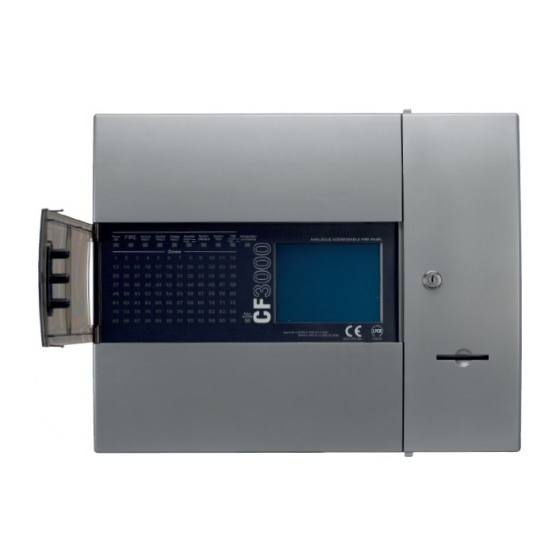
System Overview Simple User Interface The main element of the user interface with CF3000 is a large (120mm x 90mm visible area) touch screen display, which provides comprehensive user information and also acts as a multifunctional keypad. Comprehensive context sensitive help information is provided throughout the menus to assist unfamiliar users with system operation. - Page 21 Optional Printer CF3000 panels are available with optional built in printers. Where a printer is fitted, it is housed behind a printer cover door, which can be opened by means of a special tool (Supplied) to provide simple and safe access to the printer paper roll without exposure to any live equipment.
-
Page 22: Technical Specification
26 V RAW = 150 mA 5 V = 43 mA CF3000 is protected by an internal thermal device, this requires no maintenance * I max a, I max b and I min = Current as specified in BSEN54-4 Published 2006 (Amendments 1 and 2) - Page 23 This output is not to be used for fire protecting equipment or fire alarm routing equipment any power taken from the alarm system will effect the standby duration RS485 Port - Serial output port for driving CF3000 repeater panels, mimics etc. This output is short circuit protected Max cable length Min recommended cable size 1mm²...
-
Page 24: Optional Functions As Per En54 Pt 2 & 4
CF3000 - USER MANUAL Optional Functions as per EN54 Pt 2 & 4 CF3000 is approved to EN54 Parts 2 & 4 including all the following options which can be selected as required Panel Outputs Panel Sounders: (option 7.8 EN54 Pt 2) 2 pairs of outputs are provided. - Page 25 Dependencies on More Than One Alarm Signal - Type C (option 7.12.3 Of EN54 Pt 2) The CF3000 has the facility to inhibit the operation of the output sounders, output to fire routing equipment and the output of the fire protecting equipment until one more confirmatory signals are received from different zones.
- Page 26 Input 3: Disablement of the Fire Routing Equipment This input is used to disable the fire routing equipment if the CF3000. Once the FRE is disabled from this interface, it can never be enabled from the CF3000 control panel Input 4: Disablement of the Fire Protecting Equipment This input is used to disable the fire protecting equipment of the CF3000.
- Page 27 CF3000 - USER MANUAL German Interface Electrical Characteristics Inputs The inputs are designed to be actioned in one of two ways, see list below: First: A change in logic state ie. switch toggled on / off. Second: Logic pulse ie. nominal state logic high, then logic low > 200mS then return to logic high.
-
Page 28: Optional Functions Not Approved To En54 Pt 2 & 4
CF3000 - USER MANUAL Optional Functions Not Approved to EN54 Pt 2 & 4 Italian Mode: (option not required by EN54 pt2) This mode can be programmed at access level 3. This relates to points 12.2(a) and 12.2(b) of the Internal Italian Ministerial Decree 9th April 1994 which states that in the event of a fire detection from 2 or more... -
Page 29: Cable And Wiring
The mains cable must be fixed securely with a 20mm cable gland. Remove a suitably located knockout feed the cable through the gland and bolt the gland to the CF3000 backbox as shown. Secure the cable to the side of the box using the cable clip provided. -
Page 30: Installation
The screen should be earthed at the connection point provided at the CF3000 panel and not at any other point. Both the loop start and the loop end must be connected to the appropriate earthing points. -
Page 31: Fixing Details
BS5839 Pt 1 2002 The electronic components within the fire panel are Static Sensitive. Do not touch the electronics directly. Mounting the Backbox The CF3000 can be flush mount or surface mounted. 1. Surface Mount: Drill four holes and fix the backbox to the wall. 2. Flush Mount: The backbox requires a hole 364 x 472 with a depth of 117mm (standard battery / backbox ) or 217 mm if deep backbox is used. -
Page 32: External Connections
fixed to the main isolating device reading “WARNING: THIS SWITCH ALSO CONTROLS THE SUPPLY TO THE FIRE ALARM SYSTEM”. Distributed Power Supplies The above also applies to any distributed power supply (i.e. mains connections for CF3000/PR repeat units CSC354 relay units, etc.) Cable Segregation All cables for the fire alarm system should be segregated from any other cables/wiring/services. -
Page 33: Networking
CF3000 - USER MANUAL Networking Up to 126 CF3000 panels or passive repeaters can be networked together to operate as a single networked system. To achieve this each panel must be fitted with a network card (supplied at additional cost.) When operating as a networked system all fire and fault event information is displayed at every panel,... -
Page 34: Inputs/Outputs
CF3000 - USER MANUAL Input/Outputs Panel Inputs Class Change: (option not required by EN54) A pair of terminals are provided for class change. By shorting these terminals together (e.g. switch, time clock) the alarm will sound (panel sounders + loop sounders only). The panel will not indicate a fire. The alarm will cancel when the short circuit is removed. - Page 35 Under normal conditions it operates by providing 24 V dc which can be connected directly to a 24 V auxiliary device (relay). It is current limited to 30 mA. Under fault conditions or even if the CF3000 is switched off, this output will switch to 0 V. Ensure the polarity of the connections is observed at all times and end of line resistors (6k8 5%) are fitted for correct operation.
-
Page 36: Maintainance
Every 2-3 Years Replace or return the smoke detectors for cleaning to ensure correct operation and freedom from false alarms. Special equipment is required for cleaning smoke detectors. Consult Cooper Lighting and Safety. Every 5 Years Replace sealed lead acid battery. -
Page 37: Section 2 - Panel Assembly Information
CF3000 - USER MANUAL Section 2 Panel Assembly Information Section 2 - Panel Assembly Information... - Page 38 CF3000 - USER MANUAL Attaching the Door The door is designed as a drop on fit. Offer the door up to the back box in the open position as shown below. Align the hinges and lower the door onto the hinge pins. Check the hinges are secure.
-
Page 39: Installing Optional Screen Door
CF3000 - USER MANUAL Installing a Hinged Cover An option hinged cover is available as an optional extra item for CF3000. This can be fitted as standard equipment prior to despatch or retro-fitted later. The method for fitting a cover is shown below. -
Page 40: Replacing Printer Paper Roll
CF3000 - USER MANUAL Fitting Printer Paper Roll Open the printer access door on the right hand side of the panel using the key provided. Drop the paper roll into the paper holder and feed paper into the printer. The printer will then automatically pull the paper through if the panel is powered up. -
Page 41: Section 3 - Commissioning
CF3000 - USER MANUAL Section 3 Commissioning Section 3 - Commissioning... -
Page 42: Commissioning Mode
CF3000 - USER MANUAL Commissioning Mode Walk test mode allows a single engineer to test the various detectors and callpoints on a system without always having to return to the panel either to reset the system or silence the alarms. When in COMMISSIONING MODE, the system operates as normal except that when a detector or callpoint goes into alarm, the alarms only operate for a few seconds and then will silence. -
Page 43: Configuration
Detector LED Flashing The CF3000 detector flashing function is used to allow a visual inspection and confirmation that the fire panel is in communication with the installed system devices. This facility can be accessed via the engineering menu and can be switched on or off at any time as required. -
Page 44: Panel Fault Finding
CF3000 - USER MANUAL Panel Fault Finding = +5.5V ± 0.5V (No Printer Attached) = +5.5V ± 0.5V (No Printer Attached) = O/C Normal = O/C Normal S/C Fire S/C Fire = S/C Normal = S/C Normal O/C Fire O/C Fire... -
Page 45: Protocol
CF3000 - USER MANUAL Protocol Format Normal Communications to Devices: With the command bits set for the 'Normal' command and the MSB of the three mode bits set at 0, this shortened version of the normal communications to each device allows the analogue reply or status from each device to be read. -
Page 46: Pc Comissioning Software
CF3000 - USER MANUAL PC Comissioning Software Device Input Programming Fire panel reports fire from device. Fault panel reports fault from device. Reset panel resets. Silence silence all currently active sounders. Pre-Alarm panel reports pre-alarm from device. Non-Latching device won't latch in alarm condition, used in conjunction with isolates. - Page 47 CF3000 - USER MANUAL PC Comissioning Software Device Outputs Delay Configuration The output of a device when triggered can be delayed - based on a user defined value in minutes. This programming option is enabled when a value other than zero is entered inside the 'Delay' window.
- Page 48 CF3000 - USER MANUAL PC Comissioning Software Panel Outputs Dependency Type C Each panel output can be assigned a unique list of zones derived from the zones available on the loop, to activate this output, two unique zones from this list have to be in fire or alternatively any zone outside this list will trigger the output also.
-
Page 49: Section 4 - Panel Controls And Indicators
CF3000 - USER MANUAL Section 4 Panel Controls and Indicators Section 4 - Panel Controls and Indicators... - Page 50 CF3000 - USER MANUAL Panel Controls and Indicators 1. System LED’s 2. Zonal LED’s 3. Touch Screen Display 4. Printer Access Door 5. Slot for Optional Printer Powe r Powe r FIRE FIRE General General System System System System System...
-
Page 51: Panel Layout
CF3000 - USER MANUAL Panel Controls and Indicators 1. Log Book Storage 2. Insert Supervisor Key Here 3. Printer 4. Paper Roll Storage Power Power FIRE FIRE General General System System System System System System Charge Charge Battery Battery FAUL T... -
Page 52: Touch Screen Display
CF3000 - USER MANUAL Touch Screen Display Supervisor Fire Faults Disabled FRE Off Alarms 0 / Test Systems Healthy XX Zones Acitve Tuesday dd-mm-yyyy 16:25.25 BST On The touch screen is a multi-function display consisting 320 x 240 dots featuring high intensity backlighting. -
Page 53: Panel Operation
CF3000 - USER MANUAL Panel Operation CF3000 is operated via a backlit touch screen. The default fire screen is shown below. From this screen all the panels functions can be operated. The first time you touch the screen the backlight will illuminate the panel. -
Page 54: Public (Access Level 1)
CF3000 - USER MANUAL Public (Access Level 1) Public access level does not require an access code and allows anybody to review the functions outlined below. Public access level Supervisor Fire Faults Disabled FRE Off Alarms 0 / Test Systems Healthy... -
Page 55: Evacuate (Access Level 2)
CF3000 - USER MANUAL Evacuate (Access Level 2) To activate the touch screen, touch the top left corner of the screen until the screen illuminates. To enter the supervisor mode touch the supervisor button and enter the passcode. Enter the Supervisor Mode Passcode and select “Evacuate” on the menu at the top of the screen. -
Page 56: Silence Alarms
CF3000 - USER MANUAL Silence Alarms To activate the touch screen, touch the top left corner of the screen until the screen illuminates. To enter the supervisor mode touch the supervisor button and enter the passcode. Enter the Supervisor Mode Passcode and select “Silence Alarms” button as the top of... -
Page 57: Mute Buzzer
CF3000 - USER MANUAL Mute Buzzer To activate the touch screen, touch the top left corner of the screen until the screen illuminates. To enter the supervisor mode touch the supervisor button and enter the passcode. Enter the Supervisor Mode and Select “Mute Buzzer” from the Top Menu... -
Page 58: Pre Alarms
CF3000 - USER MANUAL Pre-Alarms Enter the Supervisor Mode and Select “Pre-Alarms” tab. Mute Silence Supervisor Evacuate Reset Buzzer Alarms FRE off Others View Faults View View Fires Disabled View Pre AC = 0 Alarms Pre-alarm = Some smoke / heat but below fire threshold... -
Page 59: View Faults
CF3000 - USER MANUAL Faults Enter Supervisor Mode Passcode and select “Faults” tab. Mute Silence Supervisor Evacuate Reset Buzzer Alarms FRE off Fires Others View Pre AC = 0 View Alarms View Disabled Faults Pre-alarm = Some smoke / heat but below fire threshold... - Page 60 CF3000 - USER MANUAL Enable/Disable (Others Menu) Cont. The Enable/Disable feature allows the operator to disable part or a whole system by the sub menus shown on the left. Mute Silence Supervisor Evacuate Reset Buzzer Alarms FRE Off Network Enable / Disable...
-
Page 61: Print
CF3000 - USER MANUAL Print To activate the touch screen, touch the top left corner of the screen until the screen illuminates. To enter the supervisor mode touch the supervisor button and enter the passcode. Enter the Supervisor Mode and Select the “Others” Tab. Press “Print”... -
Page 62: Lamp Test
CF3000 - USER MANUAL Lamp Test To activate the touch screen, touch the top left corner of the screen until the screen illuminates. To enter the supervisor mode touch the supervisor button and enter the passcode. Enter the Supervisor Mode and Select the “Others” Tab. Press “Lamp Test”... -
Page 63: Weekly Test
CF3000 - USER MANUAL Weekly Test To activate the touch screen, touch the top left corner of the screen until the screen illuminates. To enter the supervisor mode touch the supervisor button and enter the passcode. Select the others tab as shown below. -
Page 64: View Events
Monday 18-Feb-2001 22:20:18 Mains or battery failure The CF3000 event log stores up to 1000 events including, fires, faults, resets and address changes. Once the maximum 1000 events has been reached CF3000 will automatically overwrite the oldest event every time a new event is stored. The event log can only be reset by an approved service engineer. -
Page 65: Check Auto Config
CF3000 - USER MANUAL Check Auto Config To activate the touch screen, touch the top left corner of the screen until the screen illuminates. To enter the supervisor mode touch the supervisor button and enter the passcode. Enter the Supervisor Mode and Select the “Others” Tab. Press Check Auto Config. This feature will scan the loop and pinpoint the exact location of any break in the loop wiring and will also identify any changes in the loop configuration (e.g. -
Page 66: Replace Device
CF3000 - USER MANUAL Replace Device Replace device enables an existing device to be replaced with a new device without losing the existing text and sounder programming. Replace a single device then use use the replace device menu to allocate... -
Page 67: Test Device
CF3000 - USER MANUAL Test Device (Access Level 3) To activate the touch screen, touch the top left corner of the screen until the screen illuminates. To enter the service mode touch the supervisor button and enter engineer passcode. Enter the Service... -
Page 68: Test Zone
CF3000 - USER MANUAL Test Zone To activate the touch screen, touch the top left corner of the screen until the screen illuminates. To enter the supervisor mode touch the supervisor button and enter the service passcode. Enter the Service Mode, Select “Test” and on the Screen Shown Below Press “Test Zone”... -
Page 69: Sounder Level Test Mode
CF3000 - USER MANUAL Sounder Level Test Mode Enter the Service Mode and Select Test. From the Test Menu Select “Sounder Level Test Mode” Mute Mute Service Service Exit Reset Exit Reset Buzzer Buzzer FRE off FRE off Commission Test Device... -
Page 70: Global Led Flashing On/Off
CF3000 - USER MANUAL Global Flashing LED On/Off To activate the touch screen, touch the top left corner of the screen until the screen illuminates. To enter the supervisor mode touch the supervisor button and enter the service passcode. Enter the Service Mode and Select Test. -
Page 71: One Man Walk Test
CF3000 - USER MANUAL One Man Walk Test To activate the touch screen, touch the top left corner of the screen until the screen illuminates. To enter the supervisor mode touch the supervisor button and enter the service passcode. Enter the Service Mode and Select Test. -
Page 72: Load Cdr From Laptop
CF3000 - USER MANUAL Commission: Load CDR from Laptop To activate the touch screen, touch the top left corner of the screen until the screen illuminates. To enter the supervisor mode touch the supervisor button and enter the service passcode. -
Page 73: Download Cdr To Laptop
CF3000 - USER MANUAL Commission: Download CDR to Laptop To activate the touch screen, touch the top left corner of the screen until the screen illuminates. To enter the supervisor mode touch the supervisor button and enter the service passcode. -
Page 74: Auto Learn
CF3000 - USER MANUAL Commission: Auto Learn To activate the touch screen, touch the top left corner of the screen until the screen illuminates. To enter the supervisor mode touch the supervisor button and enter the service passcode. Enter the Service Mode and Select Commission. -
Page 75: Erase Log
CF3000 - USER MANUAL Erase Log To activate the touch screen, touch the top left corner of the screen until the screen illuminates. To enter the supervisor mode touch the supervisor button and enter the service passcode. Enter the Service Mode and Select Commission. -
Page 76: System Details
CF3000 - USER MANUAL System Details To activate the touch screen, touch the top left corner of the screen until the screen illuminates. To enter the supervisor mode touch the supervisor button and enter the service passcode. Enter the Service Mode and Select Commission, then Press “System Details”. -
Page 77: Analogue Levels
CF3000 - USER MANUAL Analogue Level To activate the touch screen, touch the top left corner of the screen until the screen illuminates. To enter the supervisor mode touch the supervisor button and enter the service passcode. Enter the Service Mode and Select Commission then press “Analogue Levels”. -
Page 78: Printer Settings
CF3000 - USER MANUAL Printer Settings To activate the touch screen, touch the top left corner of the screen until the screen illuminates. To enter the supervisor mode touch the supervisor button and enter the service passcode. Enter the Service Mode and Select Commission then press “Printer settings”. -
Page 79: Change Panel Number
CF3000 - USER MANUAL Change Panel Number To activate the touch screen, touch the top left corner of the screen until the screen illuminates. To enter the supervisor mode touch the supervisor button and enter the service passcode. Enter the Service Mode and Select Commission then press “Change Panel Number”... -
Page 80: Number Of Panels In Network
CF3000 - USER MANUAL Number of Panels in Network To activate the touch screen, touch the top left corner of the screen until the screen illuminates. To enter the supervisor mode touch the supervisor button and enter the service passcode. -
Page 81: Screen Cover
CF3000 - USER MANUAL Screen Cover To activate the touch screen, touch the top left corner of the screen until the screen illuminates. To enter the supervisor mode touch the supervisor button and enter the service passcode. Enter the Service Mode and Select Commission then press “Screen Cover”... -
Page 82: Programming I/O And Sounders
CF3000 - USER MANUAL Programming I/O and Sounders To activate the touch screen, touch the top left corner of the screen until the screen illuminates. To enter the supervisor mode touch the supervisor button and enter the service passcode. Enter the Service Mode and Select Configure. -
Page 83: Sound Settings
CF3000 - USER MANUAL Sound Settings Touch sound settings. Service Exit Reset FRE Off Sound Settings Selections from the screens below will become the global settings for all loop sounders. Service Service Exit Reset Exit Reset FRE Off FRE Off... -
Page 84: Change Date/Time
CF3000 - USER MANUAL Change Date/Time Enter the Service Mode and Select Configure. Select Change Date/Time. Service Mute Exit Reset FRE Off Buzzer Programming I/O Add/Delete and Sounders Change Date/Time Configure Heat Detectors Network Change Text Configure Zones Language Change Passcode Set the Time Using the Buttons Shown Below. -
Page 85: Change Address Text
CF3000 - USER MANUAL Change Address Text Enter the Service Mode and Select Configure. Select “Change Text” Service Mute Exit Reset FRE Off Buzzer Programming I/O Add/Delete and Sounders Change Date/Time Configure Heat Detectors Network Change Text Configure Zones Language Change Passcode Press “Change Address Text”... -
Page 86: Change Zone Text
CF3000 - USER MANUAL Change Zone Text Enter the Service Mode and Select Configure. Select “Change Text” Service Mute Exit Reset FRE Off Buzzer Programming I/O Add/Delete and Sounders Change Date/Time Configure Heat Detectors Network Change Text Configure Zones Language... -
Page 87: Change Panel Text
CF3000 - USER MANUAL Change Panel Text Enter the Service Mode and Select Configure. Select “Change Text” Service Mute Exit Reset FRE Off Buzzer Programming I/O Add/Delete and Sounders Change Date/Time Configure Heat Detectors Network Change Text Configure Zones Language... -
Page 88: Configure Zones
CF3000 - USER MANUAL Configure Zones Enter the Service Mode and Select Configure. Select “Configure Zones” Service Mute Exit Reset FRE Off Buzzer Programming I/O Add/Delete and Sounders Change Date/Time Configure Heat Detectors Network Change Text Configure Zones Language Change Passcode... -
Page 89: Change User Code
CF3000 - USER MANUAL Change User Code Enter the Service Mode and Select Configure. Select “Change User Code” Service Exit Reset FRE Off Programming I/O Add/Delete and Sounders Change Date/Time Configure Heat Detectors Network Change Text Configure Zones Language Change Passcode... -
Page 90: Add Zone
CF3000 - USER MANUAL Add Zone Enter the Service Mode and Select Configure. Select “Add Zone” Service Mute Exit Reset FRE Off Buzzer Programming I/O Add/Delete and Sounders Change Date/Time Configure Heat Detectors Network Change Text Configure Zones Language Change Passcode... -
Page 91: Delete Zone
CF3000 - USER MANUAL Delete Zone Enter the Service Mode and Select Configure, select “Add/Delete” then “Delete Zone” Service Exit Reset FRE Off Add Zone Delete Zone Add Device Delete Device Select Zone to be Service Reset Deleted FRE Off... -
Page 92: Add Device
CF3000 - USER MANUAL Add Device Enter the Service Mode and Select Configure, select “Add/Delete” then “Add Device” Service Exit Reset FRE Off Add Zone Delete Zone Add Device Delete Device Select a Loop to Add a Service Reset New Device... -
Page 93: Delete Device
CF3000 - USER MANUAL Delete Device Enter the Service Mode and Select Configure, select “Add/Delete” then “Delete Device” Service Exit Reset FRE Off Add Zone Delete Zone Add Device Delete Device Select a Device to Service Exit Reset Goto Delete... -
Page 94: Configure Heat Detectors
CF3000 - USER MANUAL Configure Heat Detectors Enter the Service Mode and Select Configure. Select “Configure Heat Detectors” Service Mute Exit Reset FRE Off Buzzer Programming I/O Add/Delete and Sounders Change Date/Time Configure Heat Detectors Network Change Text Configure Zones... -
Page 95: Network
CF3000 - USER MANUAL Network Enter the Service Mode and Select Configure. Select “Network”, This menu defines whether messages are broadcast across the network or remain local. Service Mute Exit Reset FRE Off Buzzer Programming I/O Add/Delete and Sounders Change Date/Time... -
Page 96: Password Protection
CF3000 - USER MANUAL Password Protection The Cooper CF3000 system has password protection which restricts access to the DISABLE Menu and to TEST/COMMISSIONING MODE. The password is a four digit code and the default number is 2214 for access level two and 143243 for access level three. The password entry screen is accessed via the supervisor mode button. -
Page 97: Section 5 - Appendix
CF3000 - USER MANUAL Section 5 Appendix Section 5 - Appendix... - Page 98 1. Only connect cable screen to its adjacent earth terminal. 2. For maximum spur length / load see BS5839 Pt 1:2002. 3. This unit can only be used with Cooper CAB300 detector bases and compatible detectors. Section 5 - Appendix...
-
Page 99: Way Sounder Controller
CF3000 - USER MANUAL 4 Way Sounder Controller - CSC354 Installation 1. Remove the cover of the unit. 2. Fit the back-plate in position and pass the wires into it taking care not to damage the circuit board. 3. Connect the unit according to the diagram below. -
Page 100: Zone Monitor Unit
CF3000 - USER MANUAL Zone Monitor Unit - CZMU352 Installation 1. Separate the two halves of the unit. 2. Drill out (or knock out) the required cable entries in the surface mounting backbox. 3. Fit the back-box in position and pass the wires into it. -
Page 101: Shop Monitor Unit
CF3000 - USER MANUAL Shop Monitor Unit - CSUM355 Installation 1. Separate the two halves of the unit. 2. Drill out (or knock out) the required cable entries in the surface mounting backbox. 3. Fit the back-box in position and pass the wires into it. -
Page 102: Way Input Output Unit
CF3000 - USER MANUAL 1 Way Input / Output Unit - CMIO353 Installation 1. Separate the two halves of the unit. 2. Drill out (or knock out) the required cable entries in the surface mounting back-box. 3. Fit the back-box in position and pass the wires into it. -
Page 103: Detector Base Wiring
CF3000 - USER MANUAL Detector Base Wiring - CAB300 Supply Voltage 18 - 30 V dc Cable Size 0.5 - 2.5mm² Recommended cable types FIRETUF, FP200 or MICC Mounting hole centres 50 - 80mm Wiring Hints 1. Each terminal is suitable for clamping up to 2 wires 2. -
Page 104: System Wiring
CF3000 - USER MANUAL System Wiring Section 5 - Appendix... -
Page 105: Ip66 Wall Sounder
CF3000 - USER MANUAL Weatherproof Wall Sounder - CAS881WP Installation 1. Drill required holes for the cable gland fixing 2. Drill out the required fixing holes 3. Fix to mounting surface using two suitable screws Standard Connections WARNING: Do not use high voltage testers if any equipment is connected to the system. earth screen must be continuous along entire length of loop. -
Page 106: Internal Wall Sounder
CF3000 - USER MANUAL Internal Wall Sounder - CAS881 Installation 1. Fix to mounting surface using two suitable screws - the rear gasket fits underneath the base and the sounder gasket fits inside the base. Standard Connections WARNING: Do not use high voltage testers if any equipment is connected to the system. earth screen must be continuous along entire length of loop. -
Page 107: Base Sounder
CF3000 - USER MANUAL Base Sounder - CAS380 + MASC Supply Voltage 17 ~ 32 V dc Cable Size / type 0.5 ~ 2.5mm/ FIRETUF, FP200 or MICC Standby current < 320 uA Operating temperature -10 to +55 degrees C (95%RH) Sound output @ +/-3dB (set by panel) Low volume: 84 dB @ <4 mA... -
Page 108: Way Input Output Unit
CF3000 - USER MANUAL 3 Way Input / Output Unit - CIO351 Installation 1. Separate the two halves of the unit. 2. Drill out (or knock out) the required cable entries in the surface mounting back-box. 3. Fit the back-box in position and pass the wires into it. -
Page 109: Loop Powered Beacon
CF3000 - USER MANUAL Loop Powered Beacon - CAS382 Connection Details Earth screen of cable to be continuous between beacons WARNING: Do not use high voltage testers if any equipment is connected to the system. Standard Connections Loop out Loop in... -
Page 110: Callpoint
CF3000 - USER MANUAL Callpoint - CBG370S / CBG370WP Standard Connections Loop out Loop in Analogue addressable loop Section 5 - Appendix... -
Page 111: En54 Product Spec Label
CF3000 - USER MANUAL EN54 Product Spec Label Note: X=2 on a 2 Zone Panel / X=4 on a 4 Zone Panel Label: D6K XB PR200-04-517-01 Label: D6K XA PR200-04-518-01 Powe r Powe r FIRE FIRE General General System System... -
Page 112: Battery Disposal Instructions
CF3000 - USER MANUAL Battery Disposal Instructions Although batteries contain lead and small amounts of antimony and arsenic, they are safe if handled according to the accompanying guide. The battery cells must not be dismantled as this involves several hazards, which are best handled under controlled conditions, using specialised equipment. No attempt should be made to repair any batteries;... -
Page 113: Ce Marking
CF3000 - USER MANUAL CE Marking LPCB LPCB 714h/01 0832 – CPD – 1060 714h/01 0832 – CPD – 1060 Cooper Lighting and Safety Ltd Cooper Lighting and Safety Ltd Wheatley Hall Road Wheatley Hall Road Doncaster Doncaster South Yorkshire... - Page 114 01302 303332 Email: techsupport@cooperfire.com Export Tel: 01302 303334 Fax: 01302 303345 Email: export@cooperfire.com Service Tel: 01302 303352 Fax: 01302 303332 Email: service@cooperfire.com Web: www.cooperfire.com Head Office Cooper Lighting and Safety Ltd Wheatley Hall Road Doncaster South Yorkshire DN2 4NB CC1820...
Need help?
Do you have a question about the CF3000 and is the answer not in the manual?
Questions and answers