Table of Contents
Advertisement
Quick Links
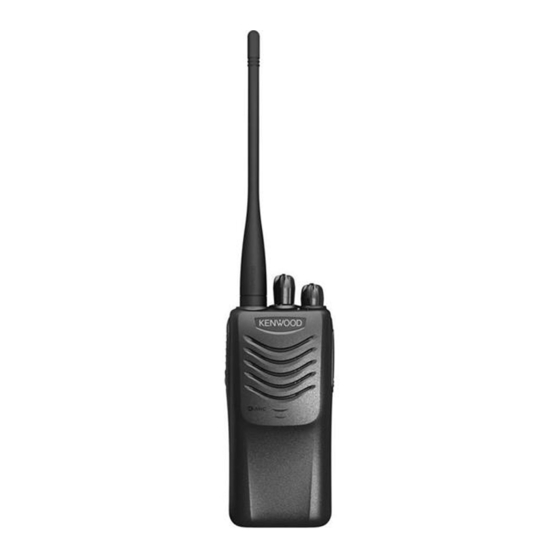
VHF FM TRANSCEIVER
TK-P701
SERVICE MANUAL
Helical antenna
(T90-1094-05)
Knob (PTT)
(K29-9489-13)
Button knob (Side)
(K29-9490-13)
Plastic cabinet assy
(A02-4135-13)
This product complies with the RoHS directive for the European market
Knob(Selector)
(K29-9488-03)
Knob (Volume)
(K29-9487-03)
.
© 2012-4 PRINTED IN JAPAN
B53-7010-10 ( Y ) PDF
CONTENTS
GENERAL ....................................................2
SYSTEM SET-UP .........................................3
REALIGNMENT ...........................................3
DISASSEMBLY FOR REPAIR .....................6
CIRCUIT DESCRIPTION .............................7
SEMICONDUCTOR DATA .........................10
COMPONENTS DESCRIPTION ................11
PARTS LIST ...............................................12
EXPLODED VIEW ......................................17
ADJUSTMENT ...........................................18
TX-RX UNIT (X57-8093-00) ....................22
SCHEMATIC DIAGRAM ............................26
BLOCK DIAGRAM .....................................30
LEVEL DIAGRAM ......................................32
SPECIFICATIONS ......................................33
This product uses Lead Free solder.
Advertisement
Table of Contents

Related Manuals for Kenwood TK-P701


Summary of Contents for Kenwood TK-P701
-
Page 1: Table Of Contents
VHF FM TRANSCEIVER TK-P701 SERVICE MANUAL © 2012-4 PRINTED IN JAPAN B53-7010-10 ( Y ) PDF CONTENTS Knob(Selector) GENERAL ............2 (K29-9488-03) SYSTEM SET-UP .........3 Helical antenna Knob (Volume) REALIGNMENT ...........3 (T90-1094-05) (K29-9487-03) DISASSEMBLY FOR REPAIR .....6 CIRCUIT DESCRIPTION ......7 SEMICONDUCTOR DATA ......10 COMPONENTS DESCRIPTION ....11... -
Page 2: General
Copyright 2012 by JVC KENWOOD Corporation. All While every precaution has been taken in the preparation rights reserved. of this manual, JVC KENWOOD Corporation assumes no No part of this manual may be reproduced, translated, responsibility for errors or omissions. Neither is any liability... -
Page 3: System Set-Up
TK-P701 SYSTEM SET-UP Merchandise received Frequency range (MHz) RF power Type Choose the type of transceiver TX/RX 136~174 5.0W TK-P701 A personal computer, programming interface (KPG-22A/22U), Transceiver programming and FPU (programming software) are required for programming. (The frequency, TX power HI/LOW, and signaling data are programmed for the transceiver.) - Page 4 TK-P701 REALIGNMENT 2. When the POWER is switched on, user mode can be Frequency (MHz) entered immediately. When the PC sends a command, 172.79375 the transceiver enters PC mode. 172.79500 When data is read from the transceiver, the red LED 172.80000...
- Page 5 TK-P701 REALIGNMENT 4. Clone mode Note: Programming data can be transferred from one trans- • The Model name and Market codes must be the same in ceiver to another by connecting them via their SP/MIC con- order to clone the transceiver.
-
Page 6: Disassembly For Repair
TK-P701 DISASSEMBLY FOR REPAIR 1. Separating the Case Assembly from the 2. Removing the TX-RX unit from the Chassis Chassis 1. Remove the two knobs ( a ). 1. Remove the packing ( e ). 2. Remove the two screws ( b ). -
Page 7: Circuit Description
TK-P701 CIRCUIT DESCRIPTION 1. Frequency Confi guration The receiver utilizes double conversion. The first IF is 38.85MHz and the second IF is 450kHz. The fi rst Local os- cillator is supplied from the PLL circuit. The PLL circuit in the transmitter generates the neces- sary frequencies. - Page 8 TK-P701 CIRCUIT DESCRIPTION 2-3. IF Amplifi er Circuit 3. Transmitter System The fi rst IF signal is passed through a four-pole mono- 3-1. Microphone Amplifi er Circuit lithic crystal fi lter (XF200) to remove the adjacent channel The signal from microphone amplifi ed by IC301 and goes signal.
- Page 9 TK-P701 CIRCUIT DESCRIPTION Note: 4. Frequency Synthesizer Circuit The EEPROM stores tuning data (Deviation, Squelch, 4-1. Frequency Synthesizer etc.). The frequency synthesizer consists of the TCXO (X1), Realign the transceiver after replacing the EEPROM. VCO, PLL IC (IC1) and buffer amplifi ers.
-
Page 10: Semiconductor Data
TK-P701 SEMICONDUCTOR DATA MCU:F2136ACNKDRB (TX-RX unit IC400) Pin No. Signal Name Function Pin No. Signal Name Function VOXIN VOX level input VREF Reference voltage input CVDET VCO voltage detection MODE Mode select for MCU LSDO Low speed data output HSDO... -
Page 11: Components Description
TK-P701 COMPONENTS DESCRIPTION TX-RX unit (X57-8093-00) Ref. No. Part Name Description Variable capaci- Ref. No. Part Name Description Frequency control/ VCO tance diode PLL System Variable capaci- Frequency control/ VCO IC200 FM IF System tance diode IC300 Diode TX/RX RF Switch... -
Page 12: Parts List
TK-P701 PARTS LIST ✽ New Parts. indicates safety critical components. L : Scandinavia K : USA P : Canada Parts without Parts No. are not supplied. Y : PX (Far East, Hawaii) T : England E : Europe Les articles non mentionnes dans le Parts No. ne sont pas fournis. - Page 13 TK-P701 PARTS LIST TX-RX UNIT (X57-8093-00) Desti- Desti- Ref. No. Address Parts No. Description Ref. No. Address Parts No. Description parts nation parts nation C122 CC73GCH1H470J CHIP C 47PF C247 CC73HCH1H470G CHIP C 47PF C123 CC73GCH1H100C CHIP C 10PF C248...
- Page 14 TK-P701 PARTS LIST TX-RX UNIT (X57-8093-00) Desti- Desti- Ref. No. Address Parts No. Description Ref. No. Address Parts No. Description parts nation parts nation C360 CK73HB1A104K CHIP C 0.10UF L212 L40-8281-86 SMALL FIXED INDUCTOR(0.82UH) C397 CK73HB1H102K CHIP C 1000PF L213 L40-5681-86 SMALL FIXED INDUCTOR(0.56UH)
- Page 15 TK-P701 PARTS LIST TX-RX UNIT (X57-8093-00) Desti- Desti- Ref. No. Address Parts No. Description Ref. No. Address Parts No. Description parts nation parts nation R136 RK73HB1J182J CHIP R 1.8K 1/16W R331 RK73HB1J473J CHIP R 1/16W R139 RK73GB2A000J CHIP R 1/10W...
- Page 16 TK-P701 PARTS LIST TX-RX UNIT (X57-8093-00) Desti- Desti- Ref. No. Address Parts No. Description Ref. No. Address Parts No. Description parts nation parts nation R505 RK73HB1J473J CHIP R 1/16W Q501 SSM3J05FU-F R508 RK73HB1J473J CHIP R 1/16W Q502 RT1P237U-T111 TRANSISTOR R509...
-
Page 17: Exploded View
TK-P701 EXPLODED VIEW S400 Cx13 MIC300 J301 J300 VR500 CF200 S402 CD200 TX-RX unit A : N09-2438-05 B : N30-2606-48 C : N83-2005-48 Parts with the exploded numbers larger than 700 are not supplied. If a part reference number is listed in a box on the exploded view of the PCB, that part does not come with the PCB. -
Page 18: Adjustment
TK-P701 ADJUSTMENT Test Equipment Required for Alignment Test Equipment Major Specifi cations Frequency Range 136 to 174MHz Standard Signal Generator (SSG) Modulation Frequency modulation and external modulation Output –127dBm/0.1µV to greater than –47dBm/1mV Input Impedance 50Ω RF Power Meter Operation Frequency... - Page 19 TK-P701 ADJUSTMENT Frequency and Signaling Preparations for Tuning the Transceiver The transceiver has been adjusted for the frequencies Before attempting to tune the transceiver, connect the shown in the following table. When required, re-adjust them unit to a suitable power supply.
- Page 20 TK-P701 ADJUSTMENT Common Section Measurement Adjustment Item Condition Specifi cations / Remarks Test- Unit Terminal Unit Parts Method equipment 1. Setting 1) BATT terminal voltage: 7.5V 2) SSG standard modulation [Wide] MOD: 1kHz, DEV: 3kHz [Narrow] MOD: 1kHz, DEV: 1.5kHz 2.
- Page 21 TK-P701 ADJUSTMENT Receiver Section Measurement Adjustment Item Condition Specifi cations / Remarks Test- Unit Terminal Unit Parts Method equipment 1. Sensitivity 1) Adj item: Low, High (2 points) TX-RX ANT Check 12dB SINAD or more Check SSG output: –115dBm SP/MIC [Narrow] (0.4µV)
-
Page 22: Pc Board
TK-P701 PC BOARD TX-RX UNIT (X57-8093-00) Component side view (J79-0362-09) R367 R392 R360 C345 C523 C329 R393 C134 C139 C353 C517 C355 C326 R136 C316 R340 R329 C319 Q103 R377 R325 C317 C354 R324 R327 R389 C360 R396 R116 R218... - Page 23 TK-P701 PC BOARD TX-RX UNIT (X57-8093-00) Component side view (J79-0362-09) C411 R408 C514 – R509 C515 C502 MIC300 IC503 Q301 IC500 C312 R508 C513 C308 C505 R502 C504 D501 R505 R511 C145 R410 R409 Q500 C315 C159 C314 R326 F500...
- Page 24 TK-P701 PC BOARD TX-RX UNIT (X57-8093-00) Foil side view (J79-0362-09) S401 S400 Side C300 C138 C136 C132 L107 L105 C135 C127 R139 L111 L110 C250 C119 D103 C116 C120 C249 C117 D203 R236 C413 C415 Q204 R228 C302 R234 C244...
- Page 25 TK-P701 PC BOARD TX-RX UNIT (X57-8093-00) Foil side view (J79-0362-09) R106 C107 C113 C152 R108 C105 R113 C110 C108 C114 R102 Q102 R114 C112 C102 L100 C119 C100 C116 R100 C120 C117 D100 R222 C262 Q203 R217 C237 C232 R225...
-
Page 26: Schematic Diagram
TK-P701 SCHEMATIC DIAGRAM TX-RX UNIT(X57-8093-00) 7 S3_A 8 S3_C 9 S3_G 4 S2_A 5 S2_C 6 S2_B 1 S1_A 2 S1_C 3 S1_B S 4 0 2 DATA DATA SELECTOR DATA S60-0447-05 CLOCK CLOCK CLOCK DACLD DACLD DACLD PTTSW PFKEY... - Page 27 TK-P701 SCHEMATIC DIAGRAM TX-RX UNIT(X57-8093-00) DATA DATA CLOCK CLOCK DACLD DACLD PFKEY PFKEY CURDET CURDET LEDR LEDR LEDG LEDG LSDO WID/NAR W/N SW T/RSHF WID: 0V NAR:5.0V WID/NAR VDCSW RSSI PFKEY Q 3 0 5 LTC014YEBFS8 THDET CVDET VOXIN 5MSC...
- Page 28 TK-P701 SCHEMATIC DIAGRAM TX-RX UNIT(X57-8093-00) PRI DRIVE R 1 0 2 R:1.03V R: 0V T:1.69V 2 . 2 k T:1.14V 2SC4926YD RF AMP TX/RX SW Q 1 0 0 R 1 5 5 D 1 0 0 C 1 0 0...
- Page 29 TK-P701 SCHEMATIC DIAGRAM TX-RX UNIT(X57-8093-00) D101 L111 L112 FINAL L108 HVC131 Q102 L107 C126 C127 D102 C131 L105 L106 C135 C137 RD07MUS2BT112 1000p 1000p HVC131 R114 DRIVE Hi:1.67V C112 Lo:1.37V Q 1 0 1 R F M 0 1 U 7 P...
-
Page 30: Block Diagram
TK-P701 BLOCK DIAGRAM X57-8093-00 MB15E03SL-E1 VHF:174.85 136M PLPS PLDL DATA Q4 :MCH3914(7)-H 2SC5108(Y)F D2,3:1SV325F CLOCK RF BUFFER RT1N141U-T111 D5:HVC350B 3.3V REG D6:HVC350B Q3:2SC5383-T111 2SC5383-T111 Q2:RT1N436U-T111 TUNE D7:DA2S101 FUSE D4:HSC277 PLUL F500 3.15A 19.2MHz L77-3074-05 RIPPLE BATT+ SHIFT SW TCXO FILTER 7.5V... - Page 31 TK-P701 BLOCK DIAGRAM VHF:136MHz~ 174MHz VHF:174.85MHz~212.85MHz (RX) 136MHz~174MHz (TX) D100,D200 Q101 Q102 D101,102:HVC131 Q100 2SC5636 HSC277 RFM01U7P RD07MUS2BT112 2SC4926YD D103:RN142S TX/RX RF AMP PRE DRIVE DRIVE AMP FINAL AMP ANT SW RF SW POWC F101 -T111 FUSE 0.5A VDCSW VDC SW...
-
Page 32: Level Diagram
TK-P701 LEVEL DIAGRAM... -
Page 33: Specifications
FM Hum & Noise ..........45dB (Wide) / 40dB (Narrow) Modulation Distortion ........... Less than 5% Measurements made per TIA/EIA-603 and specifi cations shown are typical. JVC KENWOOD Corporation reserves the right to change specifi cations without prior notice or obligation. - Page 34 TK-P701...
- Page 35 TK-P701 TK-P701 PC BOARD PC BOARD TX-RX UNIT (X57-8093-00) Component side view (J79-0362-09) TX-RX UNIT (X57-8093-00) Component side view (J79-0362-09) C411 R367 R392 R408 R360 C345 C523 C329 C514 R393 C134 – R509 C515 C139 MIC300 C502 IC503 Q301 IC500...
- Page 36 TK-P701 TK-P701 PC BOARD PC BOARD TX-RX UNIT (X57-8093-00) Foil side view (J79-0362-09) TX-RX UNIT (X57-8093-00) Foil side view (J79-0362-09) S401 S400 Side C300 R106 C107 C113 R108 C152 C105 R113 C110 C108 C114 R102 C138 C136 C132 L107 L105...
- Page 37 TX-RX UNIT(X57-8093-00) 7 S3_A 8 S3_C 9 S3_G PRI DRIVE 4 S2_A 5 S2_C R102 6 S2_B R:1.03V R: 0V 1 S1_A T:1.69V T:1.14V 2 . 2 k 2 S1_C D101 L111 L112 2SC4926YD 3 S1_B FINAL L108 RF AMP TX/RX SW Q 1 0 0 Q102...
- Page 38 X57-8093-00 VHF:136MHz~ 174MHz MB15E03SL-E1 VHF:174.85MHz~212.85MHz (RX) PLPS 136MHz~174MHz (TX) PLDL D100,D200 DATA Q4 :MCH3914(7)-H Q100 Q101 Q102 D101,102:HVC131 2SC5108(Y)F 2SC5636 HSC277 RFM01U7P RD07MUS2BT112 D2,3:1SV325F 2SC4926YD D103:RN142S CLOCK RF BUFFER TX/RX RF AMP PRE DRIVE DRIVE AMP FINAL AMP ANT SW RF SW RT1N141U-T111 D5:HVC350B...