
Summary of Contents for Total TP155001
- Page 1 GASOLINE GENERATOR TP155001,TP155001-5,UTP155001 totaltoolsworld TOTAL TOOLS WORLD...
- Page 2 FOREWORD DANGER Indicates a possibility of death or serious injury if instructions are not followed. WARNING Indicates a strong possibility of severe personal injury, loss of life and equipment damage if instructions are not followed. CAUTION Indicates a possibility of personal injury or equipment damage if instructions are not followed.
-
Page 3: Safety Instructions
1. SAFETY INSTRUCTIONS Please make sure you review each precaution carefully. WARNING Do not operate the generator near gasoline or gaseous fuel because of the potential danger of explosion or fire. Do not fill the fuel tank with fuel while the engine is running. Do not smoke or use open flame near the fuel tank. - Page 4 WARNING Do not operate in rain, in wet or damp conditions, or with wet hands. The operator may suffer severe electric shock if the generator is wet due to rain or snow. WARNING If wet, wipe and dry it well before starting. Do not pour water directly over the generator, nor wash it with water.
-
Page 5: Specifications
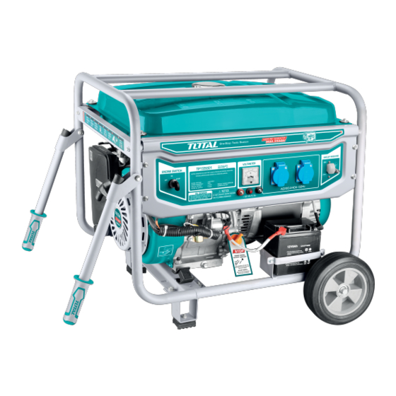
2. SPECIFICATIONS MODEL TP155001 TP155001-5 UTP155001 Type Brush, single phase Voltage regulating system AC Output 110-120~60 Rated voltage-Frequency V-Hz 220-240~50 220-240~60 220-240~60 54.1 / 23.9 Max. / Rated current 23.9 / 21.7 23.9 / 21.7 45.8 / 21.7 5.5 / 5.0 5.5 / 5.0... - Page 6 3. COMPONENTS TP155001,TP155001-5, UTP155001 1. Fuel tank Fuel valve Air filter cover Choke lever AC socket Key switch Ground (earth) terminal Oil filter cap Recoil starter 10. DC output 11. DC circuit beaker 12. Voltmeter 13. Spark plug wrench...
-
Page 7: Pre-Operation Checks
4. PRE-OPERATION CHECKS CHECK ENGINE OIL Before checking or refilling oil, be sure Oil filler cap generator is located on stable and level (Oil gauge) surface with engine stopped. Remove oil filler cap and check the engine oil level. Upper level Lower level If oil level is below the lower level line, refill with suitable oil (see table) to... -
Page 8: Check Engine Fuel
CHECK ENGINE FUEL. WARNING Do not refuel while smoking or near open flame or other such potential fire hazards. Otherwise fire accident may occur. NOTE : THIS ENGINE IS CERTIFIED TO OPERATE ON AUTOMOTIVE UNLEADED GASOLINE. LEVEL Check fuel level at fuel level gauge. If fuel level is low, refill with unleaded automotive gasoline. - Page 9 CHECKING COMPONENT PARTS Check following items before starting engine: Fuel leakage from fuel hose, etc. Bolts and nuts for looseness. Components for damage or breakage. Generator not resting on or against any adjacent wiring. CHECK GENERATOR SURROUNDINGS WARNING Make sure you review each warning in order to prevent fire hazard. Keep area clear of in flammables or other hazardous materials.
-
Page 10: Grounding The Generator
WARNING Death, personal injury and/or property damage may occur unless instructions are followed carefully. Use battery of recommended capacity. Turn the starter switch to the "STOP" position when mounting or dismounting battery. When mounting battery, connect the positive (+) cable first and then the negative (-) cable to the battery. Be careful not to short battery cables. -
Page 11: Operating Procedures
5. OPERATING PROCEDURES STARTING THE GENERATOR CAUTION Check the oil level before each operations as outlined by the article "CHECK ENGINE OIL " (a) Turn the Engine switch to the position "RUN". STOP (b) Turn the AC circuit breaker to the position "OFF". - Page 12 (e) Recoil starter model] Pull the starter handle slowly until passing the compression point (resistance will be felt), then return the handle to its original position and pull briskly. If the engine fails to start after several attempts, repeat above procedures with choke lever returned to "OPEN"...
-
Page 13: Using Electric Power
Check the amperage of the receptacles used referring to TABLE 1, and be sure not to take a current exceeding the specified amperage. Be sure that the total wattage of all appliances dose not exceed the rated output of the generator. - Page 14 Stop the generator immediately, check the appliance and / or generator for overloading or detect and have repaired as necessary by TOTAL TOOLS dealer or service shop. CAUTION The duplex 120V receptacle is protected by a GFCI (Ground Fault Circuit Interrupter).
-
Page 15: Stopping The Engine
(c) Turn the AC circuit breaker to the position "ON". (d) Turn on the switch of the appliance. VOLTAGE SWITCH Select the voltage using the VOLTAGE SWITCH in accordance with the electrical appliance. 1 2 0 V Refer to TABLE 2. 2 4 0 V 1 2 0 V CAUTION... - Page 16 (2) DC APPLICATION (Only for charging 12 volt battery) BLACK CABLE DC receptacle (Only for charging 12 volt battery) CABLE For charging 12 voltage battery, 12V-8.3A (100W) of maximum AC power can be taken out from the DC receptacle by means of the exclusive DC cable.
- Page 17 Battery Charging Procedures : 1) Stop engine. 2) Remove all connections from battery. 3) Insert the plug of exclusive DC cable into DC receptacle. 4) Connect positive (red) clip of DC cable to positive (+) terminal on battery, and then connect negative (black) clip of DC cable to negative (-) terminal on battery.
-
Page 18: Stopping The Generator
STOPPING THE GENERATOR (a) Turn off the power switch of the electric equipment and unplug the cord from receptacle of the generator. (b) Turn the AC circuit breaker to the "OFF" position. (c) Allow the engine about 3 minutes to cool down at no-load before stopping. -
Page 19: Wattage Information
Depending on their wattage output, generators will run anything from a small lamp to a number of large appliances. To determine the size generator you will need, total the wattage of the maximum number of items you will be running simultaneously. - Page 20 Don't just add up the total wattage for everything you want to power. See our section on power management to learn how to use a smaller generator to power more. See the chart below to estimate your power needs. Home Applications...
- Page 21 Approximate Approximate 240V Starting Wattage Running Wattage required element) Automatic Washer 1200 1200 Clothes Dryer (Electric) 6750 5400 Radio 50 to 200 50 to 200 Sump Pump 1/3 Horsepower 1300 1/2 Horsepower 2150 1050 Window Air Conditioner 2200 1500 (10,000 BTU) Computer Laptop 200-250...
- Page 22 Approximate Approximate 240V Starting Wattage Running Wattage required Radiant Heater 1300 1300 Laptop computer 200-250 200-250 Satellite Receiver Radio 50 to 200 50 to 200 Two-Way Radio 360W 360W 840W 840W 960W 960W Fan (portable) DVD Player Contractor Applications Approximate Starting Approximate Running Wattage Wattage...
- Page 23 Approximate Starting Approximate Running Wattage Wattage Table Saw (10 in.) 4500 1800 Industrial Motors Split Phase 1/8 Horsepower 1200 1/4 Horsepower 1700 1/3 Horsepower 1950 1/2 Horsepower 2600 Capacitor Start Induction Run 1/8 Horsepower ¼ Horsepower 1050 1/3 Horsepower 1350 ½...
- Page 24 Farm Equipment Approximate Starting Approximate Running Wattage Wattage Electric Fence, 25 miles Milk Cooler 1800 1100 Milker (vacuum pump, 2300 1000 2hp) Portable Heater (kerosene, diesel fuel) 50,000 BTU 90,000 BTU 150,000 BTU 1000 Battery Charger 15 amp 60 amp with 250-amp 1500/5750 1500/5750 boost...
-
Page 25: Voltage Drop In Electric Extension Cords
VOLTAGE DROP IN ELECTRIC EXTENSION CORDS When a long electric extension cord is used to connect an appliance or tool to the generator, a certain amount of voltage drop or loss occurs in the extension cord which reduces the effective voltage available for the appliance or tool. The chart below has been prepared to illustrate the approximate voltage loss when an extension cord of 300 feet (approx. -
Page 26: Maintenance Schedule
7. MAINTENANCE SCHEDULE DAILY INSPECTION Before running the generator, check the following service items: Enough gasoline Enough clean engine oil Loose or broken bolts and nuts Clean air cleaner element PERIODIC MAINTENANCE Periodic maintenance is vital to safe and efficient operation of your generator. Check the table below for periodic maintenance intervals. - Page 27 Periodic Maintenance Schedule table Every Every Every Every Every Maintenance Items 8 hours 50 hours 200 hours 1000 (Daily) (Weekly) (Monthly) hours hours (Daily) Clean generator and check bolt and nuts (Refill daily up to upper level) Check and refill engine oil (Initial (Every Change engine oil (*Note1)
-
Page 28: "How-To" Maintenance
8. "HOW-TO" MAINTENANCE CLEANING AND ADJUSTING SPARK PLUG (a) If the plug is contaminated with carbon, remove it using a plug cleaner or wire brush. (b) Adjust the electrode gap to 0.6 to 0.7 mm (0.024 to 0.028 in.). Gap 0.6 to 0.7 mm ( 0.024 to 0.028 in. - Page 29 CHECKING CARBON BRUSH Brush Maintenance Essentials (Effective Length) The brush is the area which touches the slip ring, and its surface must be kept smooth. If it is not smooth then carbon and other substances will adhere between the brush and slip ring.
- Page 30 Brush Maintenance Essentials (Disassembly and Assembly) Disassembly 1. Remove the two flange bolts, then remove the bracket cover. Brush 2. Remove the two flange bolts, then remove the brush. Slip ring Assembly 1. While pressing the brush against the slip ring, secure it by tightening it with the two flange bolts.
-
Page 31: Preparation For Storage
9. PREPARATION FOR STORAGE The following procedures should be followed prior to storage of your generator for periods of 6 months or longer. Drain fuel from fuel tank carefully by ■ disconnecting the fuel line. Gasoline left in the fuel tank will eventually deteriorate making engine- starting difficult. -
Page 32: Troubleshooting
Check spark plug for contamination. Remove spark plug and clean electrode. When No Electricity Is Generated at Receptacle : After making sure that the total wattage of the electrical appliance is within permissible limits and there are no Check to make sure AC circuit breaker defects in the appliance, turn the AC is in the "ON"... - Page 33 1.Cylinder head system assy. DESCRIPTION QTY/UNIT HEAD COVER COMP. BOLT HEAD COVER WASHER COMP. WASHER COVER PACKING HEAD COVER COMP. HEAD COVER PACKING FLANGE BOLT (M10×80) SPARK PLUG EXHAUST PIPE STUD BOLT CYLINDER HEAD COMP. 1.10 CARBURETOR STUD BOLT 1.11 CYLINDER HEAD SEALING PAD 1.12 DOWEL PIN (φ10×φ12×20)
- Page 34 2. Cylinder barrel DESCRIPTION QTY/UNIT FLANGE BOLT (M6×14) OIL LEVEL SWITCH ASSY. O-RING (14mm) FLANGE NUT (10 mm) CRANK CASE BALL BEARING (6207) WASHER (φ8.3×φ17×1) LOCK PIN (10 mm) GOVERNOR ARM SHAFT 2.10 OIL SEAL (φ8×φ14×5) 2.11 DRAIN PLUG WASHER (12 mm) 2.12 DRAIN PLUG BOLT 2.13...
- Page 35 3. Crankcase covers system assy. DESCRIPTION QTY/UNIT DUCT COVER FLANGE BOLT (M8×35) OIL SCALE OIL SCALE SEAL RING OIL SEAL (φ35×φ52×8) FLANGE BOLT (M8×35) CRANKCASE COVER GOVERNOR GEAR WASHER (6 mm) GOVERNOR GEAR 3.10 SLIDER SHAFT 3.11 SLIDER WASHER (6 mm) 3.12 GOVERNOR SLIDER 3.13...
- Page 36 4. Crankshaft system assy DESCRIPTION QTY/UNIT CRANK CRANKSHAFT COMP. BALANCE SHAFT...
- Page 37 5. Piston and connecting rod system assy. DESCRIPTION QTY/UNIT COMPRESSION RING A COMPRESSION RING B OIL RING A OIL RING B PISTON PIN CLIP (20 mm) PISTON PISTON PIN CONNECTING ROD CONNECTING COVER 5.10 CONNECTING ROD BOLT 5.11 PISTON RING SET...
- Page 38 6. Camshaft system assy. DESCRIPTION QTY/UNIT LOCKNUT ADJUSTING NUT ROCKER ARM ROCKER BOLT (8 mm) PUSH ROD GUIDE PLATE ROD PUSH CAM FOLLOWER CAMSHAFT EX. VALVE HELMET 6.10 EX. VALVE SPRING RETAINER 6.11 VALVE SPRING 6.12 VALVE SPRING SEAT 6.13 IN.
- Page 39 7. Recoil starter system assy. DESCRIPTION QTY/UNIT RECOIL STARTER ASSY. PLATEN SPRING RETAINER PLATEN SPRING STARTER DETENT DETENT SPRING RECOIL STARTER REEL START RETURN SPRING RECOIL STARTER CASE COMP. 7.10 RECOIL STARTER ROPE 7.11 STARTER KNOB 7.12 FLANGE BOLT (M6×8)
- Page 40 8. Fan covers system assy. DESCRIPTION QTY/UNIT SHROUD FLANGE BOLT (M6×14) FAN COVER COMP. CORD CLAMPER...
- Page 41 9. Carburetor system assy. DESCRIPTION QTY/UNIT TUBE CLIP TUBE A TUBE B WIPE HARNESS CLIP DASHPOT CHECK VALVE MANUAL CHOKE STAY ASSY. CARBURETOR IRON GASKET CARBURETOR ASSY. CARBURETOR PAPER GASKET 9.10 CARBURETOR INSULATING PLATE 9.11 INTAKE PIPE GASKET...
- Page 42 10. Flywheel system Assy. DESCRIPTION QTY/UNIT 10.1 FLYWHEEL 10.2 FLYWHEEL 10.3 SPECIAL WOODRUFF KEY 10.4 COOLING FAN 10.5 STARTER PULLEY 10.6 FLYWHEEL NUT (M16)
- Page 43 11. Ignition System Assy. DESCRIPTION QTY/UNIT 11.1 NOISE SUPPERSSOR CAP ASSY. 11.2 INGITION GOIL ASSY. 11.3 STOP SWITCH CORD 11.4 STOP SWITCH CORD HOLDER 11.5 FLANGE BOLT (M6×25) 11.6 CORD GROMMET 11.7 CHARGE COIL ASSY. 11.8 FLANGE BOLT (M6×40) 11.9 CORD CLAMPER 11.10 FLANGE BOLT (M6×20)
- Page 44 12. Starter motor System assy. DESCRIPTION QTY/UNIT 12.1 UNIT STARTER MOTOR 12.2 CONTACTOR ASSY. 12.3 FLANGE BOLT (8×35)
- Page 45 13. Control System Assy. DESCRIPTION QTY/UNIT 13.1 CONTROL ASSY. 13.2 CONTROL BASE COMP. 13.3 CONTROL ADJUSTING SPRING 13.4 CROSS POND SCREW (M5×34) 13.5 FLANGE BOLT (M6×14) 13.6 GOVERNOR SPRING 13.7 THROTTLE RETURN SPRING 13.8 GOVERNOR ROD 13.9 FLANGE NUT (M6) 13.10 GOVERNOR ARM BOLT (M6) 13.11...
- Page 46 14. Muffler System Assy. DESCRIPTION QTY/UNIT 14.1 FLANGE BOLT (M8×16) 14.2 FLANGE BOLT (M6×12) 14.3 MUFFLER STAY COMP. 14.4 MUFFLER PROTECTOR SEAL 14.5 MUFFLER SIDE PROTECTOR 14.6 MUFFLER INNER PROTECTOR COMP. 14.7 MUFFLER COMP. 14.8 MUFFLER OUTER PROTECTOR COMP. 14.9. EX.
- Page 47 15. Air cleaner DESCRIPTION QTY/UNIT 15.1 AIR CLEANER COVER COMP 15.2 AIR CLEANER ELEMENT 15.3 FLANGE NUT (M5) 15.4 AIR CLEANER SEPPARATOR 15.5 AIR CLEANER SEAL 15.6 AIR CLEANER CASE COMP 15.7 BREATHER TUBE 15.8 FLANGE NUT (M6) 15.9 AIR CLEANER STAY 15.10 AIR CLEANER ASSY.
- Page 48 16. Fuel tank system assy. DESCRIPTION QTY/UNIT 16.1 FUEL FILLER CAP COMP 16.2 FUEL FILTER 16.3 FUEL TANK COMP. 16.4 FUEL METER ASSY. 16.5 FLAT SCREW 16.6 FLANGE BOLT 16.7 AIR DUCT WASHER 16.8 TANK CUSHION COLLAR 16.9 CONTROL BOX RUBBER 16.10 FUEL TANK JOINT 16.11...
-
Page 49: Circuit Breaker
17. Control panel DESCRIPTION QTY/UNIT 17.1 CONTROL PANEL COMP. 17.2 ENGINE SWITCH ASSY. 17.3 VOLTMETER ASSY. 17.4 CIRCUIT BREAKER 17.5 ELECTRICAL OUTLET 17.6 EARTH TERMINAL SET 17.7 CONTROL PANEL CASE... - Page 50 18. Frame DESCRIPTION QTY/UNIT 18.1 FUEL TANK MOUNTING RUBBER 18.2 FRAME COMP. 18.3 FLANGE BOLT (M6×12) 18.4 FLANGE NUT (M8) 18.5 BOTTOM RUBBER (LEFT) 18.6 BOTTOM RUBBER (RIGHT) 18.7 FLANGE NUT (M10)
- Page 51 19.Rotor·Stator (1) DESCRIPTION QTY/UNIT 19.1 STATOR COVER 19.2 STATOR ASSY. 19.3 COOLING FAN 19.4 BRUSH ASSY. 19.5 TAPPING SCREW 19.6 RR HOUSING 19.7 PAN SCREW 19.8 FLANGE BOLT (M6×124) FLANGE BOLT (M6×138) 19.9 AUTOMATIC VOI REGULATOR ASSY. 19.10 GENERATOR COVER...
- Page 52 19. Rotor·Stator (2) DESCRIPTION QTY/UNIT 19.11 CABLE TIE 19.12 FLANGE BOLT 19.13 ROTOR COMP. 19.14 BEARING ASSY. 19.15 PLAIN WASHER 19.16 FLANGE BOLT (M10) 19.17 FLANGE BOLT (M5) 19.18 HEX.BOLT (M5×20) 19.19 VOLT CHANGE TERMINAL BR-AC-W 19.20 PLAIN WASHER (5mm) 19.21 HEX.
- Page 53 20. Battery Tray System Assy. DESCRIPTION QTY/UNIT 20.1 BATTERY ASSY. 20.2 BATTERY GUARD PLATE 20.3 BATTERY PLATE 20.4 BATTERY TRAY BASE 20.5 BATTERY SETTING BOLT 20.6 BATTERY SETTING PLATE 20.7 BATTERY GUARD 20.8 FRAME JOINT WASHER 20.9 EARTH CABLE ASSY. 20.10 STARTING CABLE ASSY.
- Page 54 GASOLINE GENERATOR www.totaltools.cn TOTAL TOOLS CO., PTE. LTD. MADE IN CHINA T0319.V07...
Need help?
Do you have a question about the TP155001 and is the answer not in the manual?
Questions and answers