
Related Manuals for Speck XTRAMIX X6


Summary of Contents for Speck XTRAMIX X6
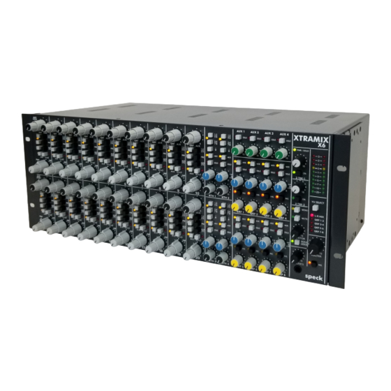
- Page 1 XTRAMIX X6 40 x 8 x 2 Line Mixer Installation and Operation Instructions ~Please Read Prior To Unpacking~ speck electronics...
- Page 2 Unpacking the X6 When you remove your XTRAMIX X6 from the shipping box and remove the foam end caps, you will see that the mounting brackets are attached to X6 so they extend beyond the front panel, and turned inward to protect the front panel knobs and buttons during shipping (See Figure 1).
- Page 3 Attaching the mounting brackets for 19” rack mount The most common use of the mounting brackets is for standard 19” rack mounting. Before attaching the brackets place the mixer on a flat surface on its rear connectors - knobs facing Use the (5) black 6-32 Phillips flat head machine screws that have been supplied to attach each mounting bracket to both sides of the mixer.
- Page 4 Attaching the mounting brackets for a desktop stand The mounting brackets can also be used to place the X6 on a desktop and elevate the mixer above the desk surface at a 10 degree angle as shown in Figure 4. Figure 4.
- Page 5 Proper Ventilation The X6 will get warm during operation so ventilation holes were placed on the top of the chassis. These ventilation holes will not be effective if another piece of rack equipment is placed directly above the X6 blocking the vent holes. It is recommended that you leave a 1U clearance on the top of the X6.
- Page 6 Power Supply Installation One of the primary reasons that the power supply of the XTRAMIX X6 is external is to insure that the power circuitry enclosed within the power supply chassis maintains a safe distance from the active electronics of the X6. For that matter, any device that has a strong magnetic or RF power field should be kept at a reasonable distance from the X6 and its audio cables.
- Page 7 Due to the high performance of the Xtramix X6, it is recommended that you use only the highest quality audio cable. A high quality cable by definition is a cable that provides good mechanical strength, high microphonic noise immunity, high frequency response, low crosstalk, and 100% shielding ability.
- Page 8 Any device that emits a high EMI (Electro Magnetic Interference) or RFI (Radio Frequency Interference) energy field should be treated with suspicion. EMI is considered any unwanted signal which adversely affects the operation of the XTRAMIX X6 or the audio system.
- Page 9 Operation Overview We hope to give you basic information on the operation of the Xtramix X6 (X6) and adequately describe its controls, switches, and connectors. The information is intended to help with the technical process when using your X6. Words alone could not adequately describe how to adjust the controls for every situation you might encounter with the X6.
-
Page 10: Input Channel
INPUT CHANNEL Each input channel has a stereo level control, pan/balance, 8 group assign, and Stereo Mix assign. 4 aux sends (2 variable sends selectable from 4 aux busses), Aux pre/post select, stereo aux select for true stereo effects send, In- place Solo, and presence of signal LED. - Page 11 6. In-Place Solo Switch - In-Place soloing allows you to isolate the stereo input channel while maintaining its stereo perspective. The source of the solo signal is post (after) the channel's level and pan controls. When a solo switch is pressed, any adjustment to the channel’s level control will be evident in the monitor and headphone playback.
- Page 12 13. Line Input Left (Mono) - This input is used to connect the left side of a stereo or dual channel source. The (mono) designation on this jack indicates that this jack should be used when you have a monaural source. 14.
-
Page 13: Aux Return Section
AUX RETURN SECTION Each stereo aux return has stereo level and pan, 8 group assign, mix assign, and In-place solo, and has active-balanced left and right ¼” TRS balanced inputs. 1. Stereo Aux Return Level - This control is a dual rotary potentiometer that simultaneously and equally adjusts both the left and right channel levels. - Page 14 X6 mix and solo busses. This interface can be used as an expander input for a Speck X.Sum mixer, or any audio product with line level outputs. 10. Group and Aux summing inputs - This DB15 connector provides a convenient way to receive external line level signals directly into the X6 group and aux busses.
- Page 15 GROUP AND AUX MASTERS Each group master has level control, pan, a stereo mix assign, in-place solo, and insert select switch. There are 4 aux master levels with solo. Each of the 8 group channels has active-balance ¼" TRS output jacks that are referenced to +4dBu, balanced ¼"...
- Page 16 6. Aux Send Master - The 4 Aux Masters provide master level control to the balanced aux send outputs on the rear panel. When matched with an effects unit that is properly operated at a professional input level of +4 dBu, the optimum setting for this pot is typically anywhere from 2 to 3 o'clock.
-
Page 17: Master Section
MASTER SECTION The master section includes a stereo master level, insert switch, a control room monitor master with A/B speaker output select, and headphone level control. The monitor section also has 2 two track returns with level control. The rear panel has a full complement of active-balance ¼"... - Page 18 6. Monitor A-B Select - This switch selects either the Monitor-A or Monitor-B outputs 7. Monitor Mute -This switch mutes the master monitor output without affecting the mix and headphone outputs. When pressed, the LED directly below will illuminate, indicating the monitor signal has been muted.
- Page 19 13. Mix Outputs - These balanced ¼" TRS jacks are the left and right outputs for the stereo master. The signal present at these jacks is adjusted with Mix Master level [#1] on the front panel. 14. Mix insert send/return - The mix master has left and right balanced ¼"...
- Page 20 Xtramix X6 Input Channel Signal Flow PRE PAN POST PAN AUX BUS SOLO BUS MIX BUS GROUP BUS...
- Page 21 Xtramix X6 Master Section Signal Flow SOLO BUS AUX BUS SOLO BUS SOLO BUS MIX BUS GROUP BUS MIX BUS GROUP BUS PRE MIX LEVEL POST MIX LEVEL SOLO BUS MIX BUS...
Need help?
Do you have a question about the XTRAMIX X6 and is the answer not in the manual?
Questions and answers