Table of Contents
Advertisement
Quick Links
Advertisement
Table of Contents

Related Manuals for Panasonic KX-TDA6178


Summary of Contents for Panasonic KX-TDA6178
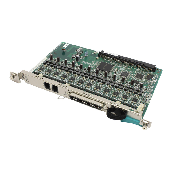
- Page 1 ORDER NO. KMS0805493CE 24-Port Single Line Telephone Extension Card with Caller ID KX-TDA6178 Model No. (for U.S.A.) © 2008 Panasonic Communications Co., Ltd. All rights reserved. Unauthorized copying and distribu- tion is a violation of law.
-
Page 2: Table Of Contents
KX-TDA6178 TABLE OF CONTENTS PAGE PAGE 1 Safety Precautions -----------------------------------------------3 1.1. For Service Technicians ---------------------------------3 2 Warning --------------------------------------------------------------3 2.1. About Lead Free Solder (PbF: Pb free) --------------3 3 Specifications ------------------------------------------------------4 4 General/Introduction ---------------------------------------------4 4.1. General Description ---------------------------------------4 5 Technical Descriptions------------------------------------------5 5.1. -
Page 3: Safety Precautions
KX-TDA6178 1 Safety Precautions 1.1. For Service Technicians • Repair service shall be provided in accordance with repair technology information such as service manual so as to prevent fires, injury or electric shock, which can be caused by improper repair work. -
Page 4: Specifications
KX-TDA6178 3 Specifications Functional Block Functional contents Extension Interface Number of Ports 24 ports SLT Interface -26V 26mA Feeding function (Voltage in ports 1-8 are switched over to -45V, depending on the circuit dis- tance.) Dial-pulse signal detecting function DTMF signal detecting function... -
Page 5: Technical Descriptions
KX-TDA6178 5 Technical Descriptions 5.1. Block Diagram BB Connector... -
Page 6: Circuit Operation
KX-TDA6178 5.2. Circuit Operation 5.2.1. Control-System Circuit 5.2.1.1. CPU Peripherals • CPU (System clock: 12.288 MHz)..IC601 Data bus: 16bit, Address bus: 23bit • Flash ROM (512Kbyte)..IC602 Flash memory consists of two areas: boot space and administration space. Administration program can be rewritten through downloading. - Page 7 KX-TDA6178 • LED Operation status indicating LED (Two colors) OFF: Fault Red ON: Fault (RESET included) Green ON: Normal (Line not in use) Green Flash (60/minute): Normal (Line in use) Orange: OUS (Because OUS needs to be controlled by MPR, reset terminal and port control terminal are Red Blinking: OUS to generate OUS) •...
- Page 8 KX-TDA6178 5.2.2. IC3 (ASIC) • EC bus interface Independent bus for 16bit/8MHz two-way address data multiplex. • CT bus interface Supports eight 8.192MHz highways (128 time slots). • Local TSW Exchanges the time slots between CT bus (1024ch) and local highway (64ch).
- Page 9 KX-TDA6178 • CODEC interface Can connect up to 12 Infineon-manufactured PEB3265, and is intended for enabling the line control. • GPIO interface Parallel interface that is arbitrarily programmable bidirectionally. 5.2.3. CODEC Function (IC201A-X) Infineon PEB3265 CODEC is installed. The analogue features such as BN, frequency characteristic, volume level, sidetone are configured by FPGA CODEC interface DCLK, CS, DOUT, DIN.
- Page 10 KX-TDA6178 5.2.4. 2W-4W Conversion It converts 4W-VOX signal used in the PBX to 2W-VOX signal used in SLT, and vice versa. It consists of an operational amplifier in the SLIC and a balanced network (B/N) in the CODEC. It can control the return loss of the audio data and frequency characteristics.
- Page 11 KX-TDA6178 5.2.6. Power Supply Voltage and current generated by the SLIC is supplied to the phones. Preset voltage is -26V, but is switched over to -45V for ports 1-8, depending on circuit distance. Current is set as 26mA. 5.2.7. Dial Pulse Detection When a telephone initiates pulse dialing, this feature detects the pulse-dialing signal.
- Page 12 KX-TDA6178 5.2.8. Hook Detection The off-hook status is detected when the telephone is off-hook. When a telephone is off-hook, change in current is detected in SLIC, and this information is transmitted to the ITA/B pin of SLIC (27, 36pin) as OFF-HOOK=L/ON HOOK=H signal. This digital signal is received by CODEC IC and recognized as off-hook signal.
- Page 13 KX-TDA6178 5.2.10. Surge Protection Thyristor is installed between T or R and FG protect from extraneous surge. 5.2.11. Self-Diagnosis A self-diagnosis relay (RL201A) is installed in A port. In the normal operation mode, it breaks the self-diagnosis relay, and in the self-diagnosis mode, it makes the self-diagnosis relay.
- Page 14 KX-TDA6178 5.2.12. Power Failure Switch Feature 4 out of 24 lines have switching relays (RL200A-D) installed in order to enable the outside call during a power failure. The line con- nected to the outside call card will be directly connected to the CN201/202 located in forward part of the board via a 4-conductor TEL cord.
- Page 15 KX-TDA6178 5.2.14. EXT-CID Transmission This Codec (IC201A-X) generates the extension Caller ID signals (FSK signal) with the CPU control. The data flow is shown below.
- Page 16 KX-TDA6178 5.2.15. Power Supply Voltage Generator • Block Diagram The input from the main power supply is in 2 voltage levels: +15V, +40V. Since the voltage levels: +15V, +3.3V, +80V, -30V and -55V are required onboard, voltage levels are generated onboard as written below.
- Page 17 KX-TDA6178 • +80V/-30V/-55V Converter For +40V input power supply, Q801 is switched ON with input voltage of 22V to start up input power supply. Q809 is switched ON with input voltage of 28V to supply 15V to control circuits in all converters. Then all converters start up. Circuit configuration of -30V/-25V converter is same as +80V.
-
Page 18: Location Of Controls And Components
KX-TDA6178 6 Location of Controls and Components 6.1. Names and Locations Overview Inside View... -
Page 19: Installation Instructions
KX-TDA6178 7 Installation Instructions 7.1. ECSLC24 Card Function ECSLC24: 24-port extension card for SLTs with Caller ID (FSK) and 4 power failure transfer (PFT) ports. Accessory and User-supplied ltems Accessories (included): Screws x 2, Ferrite core x 1 User-supplied (not included): Amphenol connector Note: •... - Page 20 KX-TDA6178 LED Indications Indication Color Description CARD STATUS Green/Red Card status indication • OFF: Power Off • Green ON: Normal (all ports are idle) • Green Flashing (60 times per minute): Normal (a port is in use) • Red ON: Fault (includes reset)
-
Page 21: Fastening Amphenol Connector
KX-TDA6178 7.2. Fastening Amphenol Connector Fastening Amphenol Connector An amphenol 57JE type connector is used on some of the optional service cards. To connect an amphenol connector, use the spring latch or screw to fix the upper part and use Velcro tape to fix the lower part of the connector. -
Page 22: Power Failure Connections
KX-TDA6178 7.3. Power Failure Connections Note: While DC power is provided by the backup batteries, the Hybrid IP-PBX will remain fully operational and the connection will not switch to the Power Failure Connection. Using Analogue Trunk Card and Extension Card Power Failure Connection connects a specific SLT and a trunk in the event of power failure. - Page 23 KX-TDA6178 RJ11 Connector Pin Assignments for Analogue Trunk Card PFT Ports 1 and 2 No. Signal Name Function Ring port 2 Ring port 1 Tip port 1 Tip port 2 PFT Ports 3 and 4 No. Signal Name Function Ring port 4...
- Page 24 KX-TDA6178 Installing Optional Service Cards 1. Insert the card along the guide rails. 2. Holding the card as follows, push the release lever in the direction of the arrow so that the card is made to engage with the connector on the back board securely.
-
Page 25: Troubleshooting Guide
KX-TDA6178 8 Troubleshooting Guide... - Page 26 KX-TDA6178...
- Page 27 KX-TDA6178...
- Page 28 KX-TDA6178...
- Page 29 KX-TDA6178...
- Page 30 KX-TDA6178...
- Page 31 KX-TDA6178...
-
Page 32: Miscellaneous
KX-TDA6178 9 Miscellaneous 9.1. Terminal Guide of the ICs Transistors and Diodes... -
Page 33: How To Replace A Flat Package Ic
KX-TDA6178 9.2. How To Replace a Flat Package IC Even if you do not have the special tools (for example, a spot heater) to remove the Flat IC, with some solder (large amount), a sol- dering iron and a cutter knife, you can easily remove the ICs that have more than 100 pins. -
Page 34: Memo
KX-TDA6178 9.3. Memo... -
Page 35: Schematic Diagram
KX-TDA6178 10 Schematic Diagram 10.1. Block Diagram BB Connector... - Page 36 50V/0.01 C152 50V/220P C123 50V/0.01 C153 50V/220P C124 50V/0.01 C154 50V/220P C125 50V/0.01 C155 50V/220P C126 50V/0.01 C156 50V/220P C127 50V/0.01 C157 50V/220P C128 50V/0.01 C158 50V/220P +3.3V IC106 L101 TP16 +1.2V VOUT +1.2V TP18 KX-TDA6178 SCHEMATIC DIAGRAM No.1 (1/2)
- Page 37 BELL_SYNC TP146 C42 50V/0.01 (nEXTPOW[1]) nHALT +3.3V C43 50V/0.01 DIAG_R DIAG_R C44 50V/0.01 TP187 DIAG_T C45 50V/0.01 DIAG_T FIL1 C46 50V/0.01 GNDA45 C47 50V/0.01 RINGER_AC TP133 C48 50V/0.01 C49 50V/0.01 10V/0.1 C50 50V/0.01 C51 50V/0.01 KX-TDA6178 SCHEMATIC DIAGRAM No.1 (2/2)
- Page 38 VBATH 12 BGNDB TP532D 10 IO1B VDDB RSYNC 33 TP533D 11 IO2B TP508D 15 VBATLB AGNDB TP534D 12 IO3B SELCLK 59 TP509D 16 VBATH16 TP535D 13 IO4B TEST 35 nRST CEXTB TP514D DA200D IC200C IC201C KX-TDA6178 SCHEMATIC DIAGRAM No.2 (1/2)
- Page 39 VBATH TP532H 12 BGNDB 10 IO1B VDDB RSYNC 33 TP533H 11 IO2B TP508H 15 VBATLB TP534H 12 IO3B SELCLK 59 AGNDB TP509H TP535H 16 VBATH16 13 IO4B TEST 35 CEXTB nRST TP514H DA200H IC200G IC201G KX-TDA6178 SCHEMATIC DIAGRAM No.2 (2/2)
- Page 40 VBATH TP532L 12 BGNDB 10 IO1B VDDB RSYNC 33 TP533L 11 IO2B TP508L 15 VBATLB TP534L 12 IO3B SELCLK 59 AGNDB TP509L TP535L 16 VBATH16 13 IO4B TEST 35 nRST CEXTB TP514L DA200L IC200K IC201K KX-TDA6178 SCHEMATIC DIAGRAM No.3 (1/2)
- Page 41 VBATH TP532P 12 BGNDB 10 IO1B VDDB RSYNC 33 TP533P 11 IO2B TP508P 15 VBATLB TP534P SELCLK 59 12 IO3B AGNDB TP509P TP535P TEST 35 16 VBATH16 13 IO4B nRST CEXTB TP514P DA200P IC200O IC201O KX-TDA6178 SCHEMATIC DIAGRAM No.3 (2/2)
- Page 42 +3.3V TP532T 12 BGNDB VDDB 10 IO1B RSYNC 33 TP533T 11 IO2B TP508T 15 VBATLB TP534T 12 IO3B SELCLK 59 AGNDB TP509T TP535T 16 VBATH16 13 IO4B TEST 35 nRST CEXTB TP514T DA200T IC200S IC201S KX-TDA6178 SCHEMATIC DIAGRAM No.4 (1/2)
- Page 43 VBATH TP532X 12 BGNDB 10 IO1B VDDB RSYNC 33 TP533X 11 IO2B TP508X 15 VBATLB TP534X 12 IO3B SELCLK 59 AGNDB TP509X TP535X 16 VBATH16 13 IO4B TEST 35 CEXTB nRST TP514X DA200X IC200W IC201W KX-TDA6178 SCHEMATIC DIAGRAM No.4 (2/2)
- Page 44 D[7] TP640 TP785 R612 IC605 R613 D[6] D[5] A[15] D[4] D[3] TP601 A[16] D[2] IC605 +3.3V A[14] D[1] TP647 A[12] D[0] IC606 A[7] TP646 A[6] A[5] IC605 A[4] +3.3V A[3] IC605 A[2] A[1] A[0] +3.3V KX-TDA6178 SCHEMATIC DIAGRAM No.5 (1/2)
- Page 45 C619 50V/220P 50V/0.01 C640 50V/220P C620 50V/0.01 C641 50V/220P C621 50V/0.01 C642 50V/220P C622 50V/0.01 C643 50V/220P C623 50V/0.01 C644 50V/220P C624 50V/0.01 C645 50V/220P C625 50V/0.01 C646 C626 50V/220P 50V/0.01 C647 C627 50V/220P 50V/0.01 KX-TDA6178 SCHEMATIC DIAGRAM No.5 (2/2)
- Page 46 KX-TDA6178 10.7. No.6...
-
Page 47: Waveform
KX-TDA6178 10.8. Waveform (300kHz) (8.192MHz) (8.192MHz) (16.384MHz) (During Ringer) (During Dial DTMF) (OFF-HOOK) - Page 48 KX-TDA6178 (4.096MHz) (12.288MHz) (Idle condition)
- Page 49 KX-TDA6178 (100kHz) (Idle condition) (190kHz) (Idle condition) (105kHz)
-
Page 50: Printed Circuit Board
D200A C614 IC201A R203B D201B DA200B IC602 C613 R201B R202B D200B C630 C211B R613 IC606 C623 Q251A Q253 C633 RL200B R253 C602 C644 C617 RL201A RA602 R252 C600 C659 IC605 CN601 R254 C660 CN101 R256 KX-TDA6178 MAIN BOARD COMPONENT VIEW... -
Page 51: Bottom View
J605 R604 R207D 12.288M L602 C208D C203C RA622 J611 C647 RA619 C646 C210D C226C C203D C618 C611 L601 C210A C208A RA613 RA612 C628 R207A C619 R207B C208B C203A RA607 RA608 C210B LA604 LA603 C226A C203B KX-TDA6178 MAIN BOARD BOTTOM VIEW... -
Page 52: Appendix Information Of Schematic Diagram
KX-TDA6178 12 Appendix Information of Schematic Diagram Note: 1. DC voltage measurements are taken with voltmeter from the negative voltage line. 2. This schematic diagram may be modified at any time with the development of new technology. -
Page 53: Exploded View And Replacement Parts List
KX-TDA6178 13 Exploded View and Replacement Parts List 13.1. IC Data 13.1.1. IC3 (ASIC) ADDRESS PIN No. SIGNAL NAME DESCRIPTIONS NOTES 1001180 Not used Not used Not used Not used Not used Not used Not used Not used 1001181 VER5... - Page 54 KX-TDA6178 ADDRESS PIN No. SIGNAL NAME DESCRIPTIONS NOTES 1001183 Not used Not used Not used Not used Not used Not used Not used Not used 1001184 Not used Not used Not used Not used Not used Not used Not used...
- Page 55 KX-TDA6178 13.1.2. IC601 (CPU) I/O MAP Pin No. Pin name Signal name Description Remarks PA15 (nIRQ3 FPGA Interrupt PA14 (nIRQ2 BELL phase detection PA13 (nIRQ1 EMPR interrupt PA12 (nIRQ0 DC power down recovery detection PA11 nRTS Serial I/F for debug...
-
Page 56: Cabinet And Electrical Parts Location
KX-TDA6178 13.2. Cabinet and Electrical Parts Location... -
Page 57: Accessories And Packing Material
KX-TDA6178 13.3. Accessories and Packing Material... -
Page 58: Replacement Parts List
KX-TDA6178 13.4. Replacement Parts List Note: Ref. Part No. Part Name & Description Remarks 1. RTL (Retention Time Limited) XYN3+F6FJ SCREW The "RTL" marking indicates that its Retention Time is 13.4.2. Accessories and Packing Materials Limited. When production is discontinued, this item will continue to be available only for Ref. - Page 59 KX-TDA6178 Ref. Part No. Part Name & Description Remarks Ref. Part No. Part Name & Description Remarks Q251A PQVTDTC123E TRANSISTOR(SI) D252 MA110 DIODE(SI) Q252 B1ABDF000026 TRANSISTOR(SI) D801 MAZ31500ML DIODE(SI) Q253 B1ABDF000026 TRANSISTOR(SI) D802 MAZ32000ML DIODE(SI) Q600 PQVTDTC114YU TRANSISTOR(SI) D803 B0HCMR000002...
- Page 60 KX-TDA6178 Ref. Part No. Part Name & Description Remarks Ref. Part No. Part Name & Description Remarks RA51 D1H81014A024 RESISTOR ARRAY, 100 RA53 D1H81024A024 RESISTOR ARRAY, 1k (FUSES) RA54 D1H81014A024 RESISTOR ARRAY, 100 K5H352A00003 FUSE RA55 D1H81014A024 RESISTOR ARRAY, 100...
- Page 61 KX-TDA6178 Ref. Part No. Part Name & Description Remarks Ref. Part No. Part Name & Description Remarks C106 F1G1H103A573 0.01 C200R F1K2E3330002 0.033 C107 F1G1H103A573 0.01 C200S F1K2E3330002 0.033 C108 ECUV1C104ZFV C200T F1K2E3330002 0.033 C109 ECUV1C104ZFV C200U F1K2E3330002 0.033 C110...
- Page 62 KX-TDA6178 Ref. Part No. Part Name & Description Remarks Ref. Part No. Part Name & Description Remarks C203S ECJ1VB1H104K C208T F1H1A684A076 0.68 C203T ECJ1VB1H104K C208U F1H1A684A076 0.68 C203U ECJ1VB1H104K C208V F1H1A684A076 0.68 C203V ECJ1VB1H104K C208W F1H1A684A076 0.68 C203W ECJ1VB1H104K C208X F1H1A684A076 0.68...
- Page 63 KX-TDA6178 Ref. Part No. Part Name & Description Remarks Ref. Part No. Part Name & Description Remarks C221Q F1K2E1040004 C229S F1G1C104A085 C221S F1K2E1040004 C229U F1G1C104A085 C221U F1K2E1040004 C229W F1G1C104A085 C221W F1K2E1040004 C601 ECUV1A105ZFV C222A F1K2E1040004 C603 F1G1H103A573 0.01 C222C F1K2E1040004...
- Page 64 KX-TDA6178 Ref. Part No. Part Name & Description Remarks Ref. Part No. Part Name & Description Remarks C821 F2A2A4700022 ERJ3GEYJ333 C823 ECJ1VB1H104K ERJ3GEYJ103 C824 ECJ1VB1H104K ERJ6GEY0R00 C826 F2A1H2210020 PQ4R10XJ153 C827 ECJ1VB1H104K ERJP08J560 C828 ECJ1VB1H104K ERJ3GEYJ223 C830 F1A2H221A086 ERJ3EKF2742 27.4k C831...
- Page 65 KX-TDA6178 Ref. Part No. Part Name & Description Remarks Ref. Part No. Part Name & Description Remarks R201D ERJ12YJ300 R204E ERJ2GEJ330 R201E ERJ12YJ300 R204F ERJ2GEJ330 R201F ERJ12YJ300 R204G ERJ2GEJ330 R201G ERJ12YJ300 R204H ERJ2GEJ330 R201H ERJ12YJ300 R204I ERJ2GEJ330 R201I ERJ12YJ300 R204J...
- Page 66 KX-TDA6178 Ref. Part No. Part Name & Description Remarks Ref. Part No. Part Name & Description Remarks R207F ERJ2RKF6800 R227M ERJ2GEJ101 R207G ERJ2RKF6800 R227O ERJ2GEJ101 R207H ERJ2RKF6800 R227Q ERJ2GEJ101 R207I ERJ2RKF6800 R227S ERJ2GEJ101 R207J ERJ2RKF6800 R227U ERJ2GEJ101 R207K ERJ2RKF6800 R227W...
- Page 67 KX-TDA6178 Ref. Part No. Part Name & Description Remarks R858 ERJ3GEYJ105 R860 ERJ8GEYJ202 R861 PQ4R10XJ682 6.8k R862 ERJ3GEYJ223 R864 ERJ3EKF2322 23.2k R865 ERJ3EKF2491 2.49k R866 ERJ3GEYJ222 2.2k R867 ERJ3GEYJ222 2.2k R868 ERJ3GEYJ272 2.7k R869 ERJ3GEYJ333 R870 ERJ3GEYJ103 R871 PQ4R10XJ752 7.5k...