Table of Contents
Advertisement
Advertisement
Table of Contents
Troubleshooting

Related Manuals for MSI B360-A PRO


Summary of Contents for MSI B360-A PRO
-
Page 1: Unpacking
Unpacking Thank you for buying the MSI B360-A PRO motherboard. Check to make sure your ® motherboard box contains the following items. If something is missing, contact your dealer as soon as possible. I/O Shield Drivers & Utilities Disc Motherboard M.2 Screw x1... -
Page 2: Safety Information
Safety Information y The components included in this package are prone to damage from electrostatic discharge (ESD). Please adhere to the following instructions to ensure successful computer assembly. y Ensure that all components are securely connected. Loose connections may cause the computer to not recognize a component or fail to start. -
Page 3: Quick Start
Quick Start Preparing Tools and Components Intel LGA 1151 CPU ® CPU Fan Thermal Paste DDR4 Memory Power Supply Unit Chassis SATA Hard Disk Drive Graphics Card SATA DVD Drive A Package of Screws Phillips Screwdriver Quick Start... -
Page 4: Installing A Processor
Installing a Processor http://youtu.be/bf5La099urI Quick Start... -
Page 5: Installing Ddr4 Memory
Installing DDR4 memory http://youtu.be/T03aDrJPyQs DIMMB2 DIMMB2 DIMMB1 DIMMA2 DIMMA2 DIMMA2 DIMMA1 Quick Start... -
Page 6: Connecting The Front Panel Header
Connecting the Front Panel Header http://youtu.be/DPELIdVNZUI HDD LED + Power LED + HDD LED - Power LED - Reset Switch Power Switch Reset Switch Power Switch JFP1 Reserved No Pin JFP1 HDD LED - HDD LED HDD LED + POWER LED - POWER LED POWER LED + Quick Start... -
Page 7: Installing The Motherboard
Installing the Motherboard Quick Start... -
Page 8: Installing Sata Drives
Installing SATA Drives http://youtu.be/RZsMpqxythc Quick Start... -
Page 9: Installing A Graphics Card
Installing a Graphics Card http://youtu.be/mG0GZpr9w_A Quick Start... -
Page 10: Connecting Peripheral Devices
Connecting Peripheral Devices Quick Start... -
Page 11: Connecting The Power Connectors
Connecting the Power Connectors http://youtu.be/gkDYyR_83I4 ATX_PWR1 CPU_PWR1 PCIE_PWR1 Quick Start... -
Page 12: Power On
Power On Quick Start... -
Page 13: Table Of Contents
Contents Unpacking ......................1 Safety Information ....................2 Quick Start ......................3 Preparing Tools and Components ................3 Installing a Processor ..................... 4 Installing DDR4 memory ..................5 Connecting the Front Panel Header ............... 6 Installing the Motherboard ..................7 Installing SATA Drives..................... - Page 14 EZ Debug LED ....................... 37 BIOS Setup ......................38 Entering BIOS Setup ..................... 38 Resetting BIOS ...................... 39 Updating BIOS ....................... 39 EZ Mode ........................ 40 Advanced Mode ....................42 SETTINGS ......................43 Advanced ....................... 43 Boot ........................50 Security ......................... 50 Save &...
-
Page 15: Specifications
M.2 slot. ** Before using Intel Optane™ memory modules, please ensure that you have ® updated the drivers and BIOS to the latest version from MSI website. y Intel B360 Chipset ® ƒ 2x USB 3.1 Gen2 (SuperSpeed USB 10Gbps) ports (1 Type-A port and 1 Type-C port on the back panel) ƒ... - Page 16 Continued from previous page y Realtek ALC892 Codec ® Audio y 7.1-Channel High Definition Audio 1x Intel I219-V Gigabit LAN controller ® y 1x PS/2 keyboard/ mouse combo port y 2x USB 2.0 Type-A ports y 1x DVI-D port y 1x DisplayPort Back Panel y 1x USB 3.1 Gen2 Type-A port Connectors...
- Page 17 RAMDISK Software y FAST BOOT y X-BOOST y DPC LATENCY TUNER y NETWORK MANAGER y CPU-Z MSI GAMING y Intel Extreme Tuning Utility ® y Google Chrome™ ,Google Toolbar, Google Drive y Norton™ Internet Security Solution Continued on next page...
- Page 18 Continued from previous page y Audio ƒ Audio Boost y Network ƒ Intel LAN with Network Manager ® y Storage ƒ Turbo M.2 y Fan ƒ Pump Fan ƒ Smart Fan Control y LED ƒ EZ DEBUG LED Special Features y Protection ƒ...
-
Page 19: Block Diagram
Block Diagram DisplayPort DVI-D 2 Channel DDR4 Memory PCI Express Bus DMI 3.0 PCI Express Bus PCIe x1 slot PCIe x1 slot 1 x M.2 PCIe x1 slot PCIe x1 slot Switch 5 x SATA 6Gb/s chipset 2 x USB 3.1 Gen2 4 x USB 3.1 Gen1 6 x USB 2.0 LPC Bus... -
Page 20: Rear I/O Panel
Rear I/O Panel Audio Ports PS/2 USB 3.1 Gen2 DisplayPort USB 2.0 USB 3.1 Gen2 Type-C DVI-D USB 3.1 Gen1 LAN Port LED Status Table Link/ Activity LED Speed LED Status Description Status Description No link 10 Mbps connection Yellow Linked Green 100 Mbps connection... -
Page 21: Realtek Hd Audio Manager
Realtek HD Audio Manager After installing the Realtek HD Audio driver, the Realtek HD Audio Manager icon will appear in the system tray. Double click on the icon to launch. Device Selection Advanced Settings Jack Status Application Enhancement Main Volume Connector Strings Profiles... - Page 22 Audio jacks to headphone and microphone diagram Audio jacks to stereo speakers diagram AUDIO INPUT Audio jacks to 7.1-channel speakers diagram AUDIO INPUT Front Center/ Subwoofer Side Rear Rear I/O Panel...
-
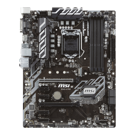
Page 23: Overview Of Components
Overview of Components DIMMA1 PCIE_PWR1 DIMMA2 CPU_FAN1 DIMMB1 CPU_PWR1 DIMMB2 CPU Socket SYS_FAN1 PUMP_FAN1 SYS_FAN5 SYS_FAN4 EZ Debug LEDs ATX_PWR1 JUSB4 JBAT1 M2_1 PCI_E1 PCI_E2 SATA▼2▲3 PCI_E3 SATA▼4▲5 PCI_E4 SATA1 PCI_E5 JTPM1 PCI_E6 JTBT1 JFP1 JFP2 JUSB1 JAUD1 JUSB2 SYS_FAN2 SYS_FAN3 JCOM1 JCI1... - Page 24 Component Contents Port Name Port Type Page CPU_FAN1,SYS_FAN1~5, PUMP_FAN1 Fan Connectors CPU_PWR1, ATX_PWR1, PCIE_PWR1 Power Connectors CPU Socket LGA1151 CPU Socket DIMMA1/ A2/ B1/ B2 DIMM Slots JAUD1 Front Audio Connector JBAT1 Clear CMOS (Reset BIOS) Jumper JCI1 Chassis Intrusion Connector JCOM1 Serial Port Connector JFP1, JFP2...
-
Page 25: Cpu Socket
Always unplug the power cord from the power outlet before installing or removing the CPU. Please retain the CPU protective cap after installing the processor. MSI will deal with Return Merchandise Authorization (RMA) requests if only the motherboard comes with the protective cap on the CPU socket. -
Page 26: Dimm Slots
DIMM Slots DIMMA1 DIMMB1 Channel A Channel B DIMMA2 DIMMB2 Memory module installation recommendation DIMMB2 DIMMB2 DIMMB1 DIMMA2 DIMMA2 DIMMA2 DIMMA1 Important Always insert memory modules in the DIMMA2 slot first. Due to chipset resource usage, the available capacity of memory will be a little less than the amount of installed. -
Page 27: Pci_E1~6: Pcie Expansion Slots
If you install a large and heavy graphics card, you need to use a tool such as MSI Gaming Series Graphics Card Bolster to support its weight and to prevent deformation of the slot. Overview of Components... -
Page 28: M2_1: M.2 Slot (Key M)
M2_1: M.2 Slot (Key M) Video Demonstration Watch the video to learn how to Install M.2 module. http://youtu.be/JCTFABytrYA Important Intel RST only supports PCIe M.2 SSD with UEFI ROM. ® Intel Optane Memory Ready. ® Installing M.2 SSD 1. Loosen the M.2 riser screw from the 3. -
Page 29: Sata1~5: Sata 6Gb/S Connectors
SATA1~5: SATA 6Gb/s Connectors These connectors are SATA 6Gb/s interface ports. Each connector can connect to one SATA device. SATA3 SATA2 SATA5 SATA4 SATA1 Important SATA1 port will be unavailable when an M.2 SATA SSD module has been installed in the M.2 slot. -
Page 30: Cpu_Pwr1, Atx_Pwr1, Pcie_Pwr1: Power Connectors
CPU_PWR1, ATX_PWR1, PCIE_PWR1: Power Connectors These connectors allow you to connect an ATX power supply. CPU_PWR1 Ground +12V Ground +12V Ground +12V Ground +12V +3.3V +3.3V +3.3V -12V Ground Ground PS-ON# Ground Ground Ground ATX_PWR1 Ground Ground PWR OK 5VSB +12V +12V +3.3V... -
Page 31: Jfp1, Jfp2: Front Panel Connectors
JFP1, JFP2: Front Panel Connectors These connectors connect to the switches and LEDs on the front panel. JFP1 HDD LED + Power LED + HDD LED - Power LED - Reset Switch Power Switch Reset Switch Power Switch Reserved No Pin Speaker - Buzzer + JFP2... -
Page 32: Jusb1~2: Usb 2.0 Connectors
However, when you boot the computer into Windows ® you will need to install the MSI SUPER CHARGER application to turn ON/OFF the ®... -
Page 33: Cpu_Fan1,Sys_Fan1~5, Pump_Fan1: Fan Connectors
CPU_FAN1,SYS_FAN1~5, PUMP_FAN1: Fan Connectors Fan connectors can be classified as PWM (Pulse Width Modulation) Mode or DC Mode. PWM Mode fan connectors provide constant 12V output and adjust fan speed with speed control signal. DC Mode fan connectors control fan speed by changing voltage. When you plug a 3-pin (Non-PWM) fan to a fan connector in PWM mode, the fan speed will always maintain at 100%, which might create a lot of noise. -
Page 34: Jaud1: Front Audio Connector
JAUD1: Front Audio Connector This connector allows you to connect audio jacks on the front panel. MIC L Ground MIC R Head Phone R MIC Detection SENSE_SEND No Pin Head Phone L Head Phone Detection JCI1: Chassis Intrusion Connector This connector allows you to connect the chassis intrusion switch cable. Normal Trigger the chassis intrusion event... -
Page 35: Jtpm1: Tpm Module Connector
JTPM1: TPM Module Connector This connector is for TPM (Trusted Platform Module). Please refer to the TPM security platform manual for more details and usages. LPC Clock 3V Standby power LPC Reset 3.3V Power LPC address & data pin0 Serial IRQ LPC address &... -
Page 36: Jcom1: Serial Port Connector
JCOM1: Serial Port Connector This connector allows you to connect the optional serial port with bracket. SOUT Ground No Pin JLPT1: Parallel Port Connector This connector allows you to connect the optional parallel port with bracket. RSTB# AFD# PRND0 ERR# PRND1 PINIT# PRND2... -
Page 37: Jbat1: Clear Cmos (Reset Bios) Jumper
JBAT1: Clear CMOS (Reset BIOS) Jumper There is CMOS memory onboard that is external powered from a battery located on the motherboard to save system configuration data. If you want to clear the system configuration, set the jumper to clear the CMOS memory. Keep Data Clear CMOS/ Reset BIOS... -
Page 38: Bios Setup
Press Delete key, when the Press DEL key to enter Setup Menu, F11 to enter Boot Menu message appears on the screen during the boot process. y Use MSI FAST BOOT application. Click on GO2BIOS button and choose OK. The system will reboot and enter BIOS setup directly. -
Page 39: Resetting Bios
Updating BIOS Updating BIOS with M-FLASH Before updating: Please download the latest BIOS file that matches your motherboard model from MSI website. And then save the BIOS file into the USB flash drive. Updating BIOS: 1. Press Del key to enter the BIOS Setup during POST. -
Page 40: Ez Mode
EZ Mode At EZ mode, it provides the basic system information and allows you to configure the basic setting. To configure the advanced BIOS settings, please enter the Advanced Mode by pressing the Setup Mode switch or F7 function key. XMP switch Setup Mode switch Screenshot... - Page 41 y Information display - click on the CPU, Memory, Storage, Fan Info and Help buttons on left side to display related information. y Function buttons - enable or disable the LAN Option ROM, M.2/ Optane Genie, HD audio controller, AHCI, RAID, CPU Fan Fail Warning Control and BIOS Log Review by clicking on their respective button.
-
Page 42: Advanced Mode
Advanced Mode Press Setup Mode switch or F7 function key can switch between EZ Mode and Advanced Mode in BIOS setup. XMP switch Setup Mode switch Screenshot Search Language System information Boot device priority bar BIOS menu BIOS menu selection selection Menu display y XMP switch/ Setup Mode switch/ Screenshot/ Language/ System information/ Boot... -
Page 43: Settings
SETTINGS System Status f System Date Sets the system date. Use tab key to switch between date elements. The format is <day> <month> <date> <year>. <day> Day of the week, from Sun to Sat, determined by BIOS. Read-only. <month> The month from Jan. through Dec. <date>... - Page 44 fPEG X - Max Link Speed [Auto] Sets PCI Express protocol of PCIe x16 slots for matching different installed devices. [Auto] This item will be configured automatically by BIOS. [Gen1] Enables PCIe Gen1 support only. [Gen2] Enables PCIe Gen2 support only. [Gen3] Enables PCIe Gen3 support only.
- Page 45 fIpv4 PXE Support [Enabled] When Enabled, the system UEFI network stack will support Ipv4 protocol. This item will appear when Network Stack is enabled. [Enabled] Enables the Ipv4 PXE boot support. [Disabled] Disables the Ipv4 PXE boot support. fIpv6 PXE Support [Enabled] When Enabled, the system UEFI network stack will support Ipv6 protocol.
- Page 46 fIGD Multi-Monitor [Disabled] Enables or disables the multi-screen output from integrated graphics and external graphics card. This item appears when Initiate Graphic Adapter set to PEG. [Enabled] Enables multi-screen function for both integrated and external graphics cards. [Disabled] Disables this function. f Thunderbolt Configuration Sets the thunderbolt device function.
- Page 47 fParallel (LPT) Port Settings [Auto] Sets parallel port (LPT). If set to Auto, BIOS will optimize the IRQ automatically or you can set it manually. fDevice Mode [STD Printer Mode] Selects an operating mode for parallel port. [STD Printer Mode] Printer port mode [SPP] Standard Parallel Port mode...
- Page 48 Fast Boot [Disabled] MSI Fast Boot is the fastest way to boot the system. It will disable more devices to speed up system boot time which is faster than the boot time of Fast Boot. [Enabled] Enables the MSI Fast Boot function to speed up booting time. And the following Fast Boot field will be disabled and fixed.
- Page 49 fResume By RTC Alarm [Disabled] Disables or enables the system wake up by RTC Alarm. [Enabled] Enables the system to boot up on a scheduled time/ date. [Disabled] Disables this function. fDate (of month) Alarm/ Time (hh:mm:ss) Alarm Sets RTC alarm date/ Time. If Resume By RTC Alarm is set to [Enabled], the system will automatically resume (boot up) on a specified date/hour/minute/second in these fields (using the + and - keys to select the date &...
-
Page 50: Boot
f Intel ( R ) Ethernet Connection I219-V Shows driver information and configuration of the ethernet controller parameter. This item will appear when Network Stack is enabled. Boot Sets the sequence of system boot devices. f Full Screen Logo Display [Enabled] Enables or disables to show the full screen logo while system POST. - Page 51 f User Password Sets User Password for system security. User has limited rights to change the BIOS items with user password. This item will be available when administrator password is set. After setting the user password, the state of this item will show “Installed” . f Password Check [Setup] Selects a condition that will request the password.
-
Page 52: Save & Exit
Save & Exit f Discard Changes and Exit Exit BIOS setup without saving any change. f Save Changes and Reboot Save all changes and reboot the system. f Save Changes Save current changes. f Discard Changes Discard all changes and restore to the previous values. f Restore Defaults Restore or load all default values. - Page 53 Important Overclocking your PC manually is only recommended for advanced users. Overclocking is not guaranteed, and if done improperly, it could void your warranty or severely damage your hardware. f OC Explore Mode [Normal] Enables or disables to show the normal or expert version of OC settings. [Normal] Provides the regular OC settings in BIOS setup.
- Page 54 f CPU Ratio Offset When Running AVX [Auto] Sets a offset value to lower the CPU core ratio. It could be helpful for heat dissipation when running AVX instruction set. If set to Auto, BIOS will configure this setting automatically. This item appears when the installed CPU supports this function. f Ring Ratio [Auto] Sets the ring ratio.
- Page 55 f Memory Try It ! [Disabled] It improve memory compatibility or performance by choosing optimized memory preset. f DRAM Timing Mode [Link] Selects the memory timing mode. [Link] Allows user to configure the DRAM timing for all memory channel. [UnLink] Allows user to configure the DRAM timing for respective memory channel.
- Page 56 f MEMORY-Z Press Enter to enter the sub-menu. This sub-menu displays all the settings and timings of installed memory. You can also access this information menu at any time by pressing [F5]. fDIMMA1/A2/B1/B2 Memory SPD Press Enter to enter the sub-menu. The sub-menu displays the information of installed memory.
- Page 57 fAdjacent Cache Line Prefetch [Enabled] Enables or disables the CPU hardware prefetcher (MLC Spatial prefetcher). [Enabled] Enables adjacent cache line prefetching for reducing the cache latency time and tuning the performance to the specific application. [Disabled] Enables the requested cache line only. fCPU AES Instructions [Enabled] Enables or disables the CPU AES (Advanced Encryption Standard-New Instructions) support.
- Page 58 fShort Duration Power Limit (W) [Auto] Sets the short duration TDP power limit for CPU in Turbo Boost mode. fCPU Current Limit (A) [Auto] Sets maximum current limit of CPU package in Turbo Boost mode. When the current is over the specified value, the CPU will automatically reduce the core frequency for reducing the current.
-
Page 59: M-Flash
M-FLASH provides the way to update BIOS with a USB flash drive. Please down-load the latest BIOS file that matches your motherboard model from MSI website, save the BIOS file into your USB flash drive. And then follow the steps below to update BIOS. -
Page 60: Oc Profile
OC PROFILE f Overclocking Profile 1/ 2/ 3/ 4/ 5/ 6 Overclocking Profile 1/ 2/ 3/ 4/ 5/ 6 management. Press <Enter> to enter the sub- menu. fSet Name for Overclocking Profile 1/ 2/ 3/ 4/ 5/ 6 Name the current overclocking profile. fSave Overclocking Profile 1/ 2/ 3/ 4/ 5/ 6 Save the current overclocking profile. -
Page 61: Hardware Monitor
HARDWARE MONITOR Temperature & Speed Fan Manage Setting Buttons Temperature/ Voltage display f Temperature & Speed Shows the current CPU temperature, system temperature and fans' speeds. f Fan Manage ƒ PWM - allows you to select the PWM mode for fan operation. ƒ... - Page 62 BIOS Setup...
-
Page 63: Software Description
Software Description Please download and update the latest utilities and drivers at www.msi.com Installing Windows ® 1. Power on the computer. 2. Insert the Windows 10 disc into your optical drive. ® 3. Press the Restart button on the computer case. -
Page 64: App Manager
Motherboard Information - shows the model name of motherboard. y Total Install/ Update - click on this tab to update/ install all the applications. Important Please note that, once you uninstall the APP MANAGER, all the MSI applications and software will be uninstalled simultaneously. Software Description... -
Page 65: Live Update 6
LIVE UPDATE 6 LIVE UPDATE 6 is an application for the MSI system to scan and download the latest ® drivers, BIOS and utilities. With LIVE UPDATE 6, you don’ t need to search the drivers on websites, and don’ t need to know the models of motherboard and graphics cards. - Page 66 1. Select the Live Update tab. 2. Choose Automatic scan, system will automatically scan all the items and search for the latest update files. Or you can choose Manual scan and select the items you wish to scan. 3. Click the Scan button at the bottom. It may take several moments to complete the process.
-
Page 67: Command Center
COMMAND CENTER COMMAND CENTER is an user-friendly software and exclusively developed by MSI, helping users to adjust system settings and monitor status under OS. With the help of COMMAND CENTER, making it possible to achieve easier and efficient monitoring process and adjustments than that under BIOS. In addition, the COMMAND CENTER can be a server for mobile remote control application. - Page 68 CPU Fan CPU Fan control panel provides Smart mode and Manual Mode. You can switch the control mode by clicking the Smart Mode and Manual Mode buttons on the top of the CPU Fan control panel. y Manual Mode - allows you to manually control the CPU fan speed by percentage.
- Page 69 Option Buttons - Advanced When click the Advanced button, The Voltage, Fan and DRAM icons will appear. y Voltage - allows you to adjust advanced voltage values of CPU and chipset. y Fan - allows you to control the system fans speed. y DRAM - shows the current Advanced DRAM parameters, and allows you to change the settings by selecting values from the drop-down menu on the right hand side.
- Page 70 7. Find the IP address on the SoftAP Management Setting area, and enter the IP address on your MSI COMMAND CENTER APP to link your system. ® 8. Press Refresh on the MSI COMMAND CENTER APP to verify that monitoring and ® OC functions are working properly.
-
Page 71: X-Boost
X-BOOST The MSI X-BOOST allows you to select the system performance mode to meet your current system environment or support faster storage access speed for your external storage or memory cards. Easy In Easy page, you can select one system performance mode to meet the current system environment. - Page 72 OPTANE BOOST - supports faster access speed of Intel Optane memory (require a reboot). Important Please note that you can only select one mode at a time from Easy or Advance page as MSI X-BOOST function. The improved transfer rate/ access speed will vary with the USB/ storage device. Software Description...
-
Page 73: Smart Tool
SMART TOOL SMART TOOL is a convenient tool that can help you to create your Windows installation USB flash drive, and it can also create a super RAID. Main menu After installing and activating SMART TOOL, it will display a main menu for you to choose Smart Tool or SUPER RAID. - Page 74 SUPER RAID This utility allows you to create a super RAID in Windows system. To create a super RAID: 1. Use checkboxs to select the disks you want included in your RAID. 2. Choose Speed Up or Backup for RAID type. y Speed Up = RAID0 y Backup = RAID1 3.
-
Page 75: Ramdisk
RAMDISK RAMDISK creates a virtual RAM drive using the available memory in your computer, the performance of the RAMDISK is faster than an SSD and hard drive. RAMDISK allows you to store any temporary information on it. Furthermore, using the RAMDISK will extend your SSD’... -
Page 76: Network Manager
NETWORK MANAGER NETWORK MANAGER is an utility for traffic shaping for the Windows 10. It can keep your internet fast during heavy upload/ download and improve your ping for online games. If your motherboard has a Wi-Fi module, NETWORK MANAGER provides virtual access point function for traffic shaping for your mobile devices. - Page 77 Configuring Bandwidth This section describes how to configure Internet Provider Speed. You can configure default internet upload and download bandwidth from the Network Test tab on the NETWORK MANAGER window. Important Before using the NETWORK MANAGER for the first time, you should use the Test Network Speed button which runs a speed test of your current total Internet bandwidth delivered through your Internet service provider.
-
Page 78: Intel ® Optane™ Memory Configuration
Optane™ memory can accelerate the Windows 10 64bit operating system. This ® section describes how to install and remove the Intel Optane™ memory. ® System Requirements y Intel Optane™ memory ready MSI motherboards ® ® y Supported 8th Gen, or later, Intel Core™ - i Processor ®... - Page 79 5. Enable Intel Optane™ Memory. ® ˜ Enable Intel Optane™ Memory via the Intel Optane™ memory application ® ® (auto-launches upon reboot). ˜ Click Yes in the dialog. ˜ Reboot System. WARNING Once you enable Intel Optane™ memory, in order to prevent seriously damage your ®...
-
Page 80: Removing The Intel ® Optane™ Memory
Removing the Intel Optane™ memory ® If you no longer want to use Intel Optane™ memory, you have to disable the Intel ® ® Optane™ memory before removing the Intel Optane™ memory module to avoid ® operating system damage. Please follow the steps below to remove the Intel Optane™... -
Page 81: Troubleshooting
® Optane Memory and switch BIOS setting from RAID/ Optane mode back to AHCI mode, that may cause operating system damage. MSI has developed a software assistance for this problem. You can disable Intel Optane™ Memory and switch back to AHCI ®... -
Page 82: Troubleshooting
Troubleshooting Lost BIOS password Before sending the motherboard for RMA repair, try to go over troubleshooting y Clear the CMOS, but that will cause guide first to see if your got similar you to lose all customized settings in the symptoms as mentioned below. -
Page 83: Regulatory Notices
EMC Directive 2014/30/EU; RoHS Directive 2011/65/EU. Compliance with these directives is assessed using applicable European Harmonized Standards. The point of contact for regulatory matters is MSI, MSI-NL Eindhoven 5706 5692 ER Son. B급 기기 (가정용 방송통신기자재) 이 기기는 가정용(B급) 전자파적합기기로서 주... - Page 84 MSI will comply with the product take entregar a una empresa autorizada para la recogida de back requirements at the end of life of MSI-branded estos residuos.
- Page 85 MSI si adeguerà a tale Direttiva ritirando tutti i prodotti marchiati MSI che sono stati venduti all’interno dell’Unione Europea alla fine del loro ciclo di vita.
- Page 86 Micro-Star Int’ l Co., Ltd. All other marks and names mentioned may be trademarks of their respective owners. No warranty as to accuracy or completeness is expressed or implied. MSI reserves the right to make changes to this document without prior notice. Technical Support...
Need help?
Do you have a question about the B360-A PRO and is the answer not in the manual?
Questions and answers