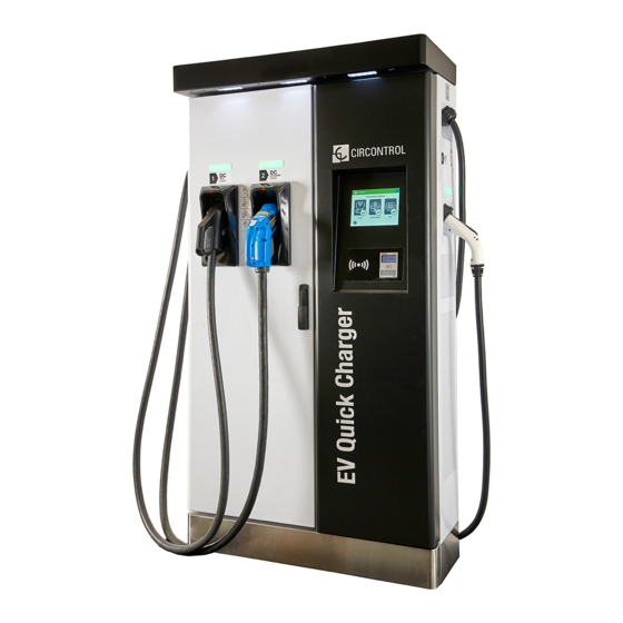
Circontrol Raption 50 Series User Manual
Hide thumbs
Also See for Raption 50 Series:
- User manual (4 pages) ,
- Quick start installation manual (24 pages)
Table of Contents
Advertisement
Advertisement
Table of Contents

Related Manuals for Circontrol Raption 50 Series


Summary of Contents for Circontrol Raption 50 Series
- Page 1 Raption 50 Series User Manual...
- Page 3 C O P Y R I G H T I N F O R M AT I O N This document is copyrighted, 2020 by Circontrol, S.A. All rights are reserved. Circontrol, S.A. reserves the right to make improvements to the products described in this manual at any time without notice.
- Page 5 Here is your guide to use and configure Raption 50 Series 1 — So, Hello! 2 — Features A - Main features B - Overview C - Dimensions D - Status Beacon lights E - Connectors 3 — How to use it?
- Page 6 Raption 50 Series User Manual G - Emergency button H - Connectors status I - Consulting the connectors status J - Errors 4 — How to configure it? A - Introduction B - What is needed? C - Network topology...
- Page 7 7 — Monitoring A - Introduction B - CirCarLife client - Connection C - CirCarLife client - Overview D - CirCarLife client - Devices E - CirCarLife client - Graphs F - CirCarLife client - Tables G - CirCarLife client - Events 8 —...
- Page 8 Charge Point and helps the user to perform charging with a high level of efficiency and safety. The CIRCONTROL Charge Point provides the fastest way to charge electric vehicles nowadays. Its innovative and original design provides a quick and intuitive way for recharging the electric vehicles, according to the current regulations.
- Page 9 IEC for users (broken connectors, caps 61851. that don’t close...). • Do not modify the Charge Point. If • Use only Circontrol supplied spare modified, CIRCONTROL will reject all parts. responsibility and the warranty will be void.
- Page 10 Raption 50 Series Instruction Manual Main features • HMI: there is a TFT colour touch screen of 8 inches, is the interface between the Charge Point and the user. Provides detailed information for starting and stopping the charge, including information concerning the recharge that is in progress (charge state of the battery, charging time remaining, etc).
- Page 11 Features Overview 1- Cover Exit AC cable 3- AC light beacon 4- CHAdeMO connector 5- Unit air inlet 6- Power Modules 7- Decorative front 8- Decorative rear 9- Handle 10- CHAdeMO air outlet panel panel holder 11- CCS holder 12- AC holder or 13- CCS light beacon 14- CHAdeMO light 15- Antenna socket 32A *...
- Page 12 Raption 50 Series User Manual Dimensions • Units specified in millimeters:...
- Page 13 Status Beacon lights Over each connector there is a beacon light, it indicates the state of charge in which the socket/connector is located. Colour Status Description Green Available The connector or socket is available to start a charging session Blue Charging The connector or socket is performing a charging session Cyan...
- Page 14 Raption 50 Series User Manual Connectors The Charge Point is equipped with three connectors of different load; these can recharge a large range of vehicles: • AC (Mode 3): Type 2 tethered cable (63A/44kW) or Type 2 socket (32A/22kW)* • DC (Mode 4): CHAdeMO, Tethered cable, 3m. Until 125 A / 50 kW •...
- Page 15 Watch Out!! If your Charge Point is equipped with the ‘Mechanical connector locking’ accesory at DC holders, is not possible to pull back the connectors from holders without first unlocking it. There are one label placed between the CHAdeMO and the CCS holders explaining about this function.
- Page 16 Raption 50 Series User Manual The connectors will be delivered right in the moment than the user push over the ‘Connector touching button’ when choose the option in the HMI screen: At the AC side for every Charge Point (It is not an optional device) there is a manual lock for keeping the connector, follow the indications shown on the label in order to remove the AC connector.
- Page 18 Raption 50 Series User Manual General The first time the Charge Point is powered on, the system will take around 10 seconds for starting up, the screen will show next image: In the lower right corner, it shows the firmware version. After that 10 seconds have...
- Page 19 How to use it ? At this new screen, the Charge Point is asking for showing the identification card or touch the screen, as you can see there are two options. The first option, showing the identification card, is the option that will let to initiate a ‘Charging session’...
- Page 20 Raption 50 Series User Manual Next screen will appear, press over your language’s flag:...
- Page 21 Starting a charging session - Once you have shown your identification card, the HMI will show next screen: Wait while Charge Point performs identification - If everything is correct and the user is authorized, the HMI will show next screen:...
- Page 22 Raption 50 Series User Manual - Now, the user can choose the connector, always depending of the sort of vehicle that you have and if the connector status is available: At any time is possible to press over this button in order to go back to the “identification screen”.
- Page 23 2- Checking vehicle connection… Please wait - In a few seconds, the charging session will start and the HMI will show the charging process. Pressing over this button, the screen will go back to the “identification screen”.
- Page 24 Raption 50 Series User Manual Special events starting a charge A - “Not authorized”: some Charge Points could be working under the supervision of the main management system, called Back Office. It can generate a whitelist in order to register new users, manage charging sessions, etc. If the user is not authorized, the HMI will show the following message: B - “Authorization failed”: if there is some communication problem with the Back...
- Page 25 C - “Not authorized, Concurrent charge”: in this case, the identifier is already involved in another charge transaction: D - “Not authorized, Authorization expired”: is possible that the back office has put deadline to your identification card and this date is already expired:...
- Page 26 Raption 50 Series User Manual E - “Not authorized, Authorization blocked”: is possible that the back office has blocked temporarily your identification card. F – After the user has been properly authorized and just at the moment that has to choose the connector, the screen will show the connectors status, it could appear some problem.
- Page 27 G - Another issue that can occur is “Vehicle not detected”, unlock the connector, connect again and press over ‘Retry’ button. H – Almost all vehicles cannot charge if the shift lever is not in parking mode position. This situation can be detected for the Charge Point and it will be displayed by HMI as “Please, check vehicle shift position, put in parking mode”, after press over ‘Retry’...
- Page 28 Raption 50 Series User Manual I – Is possible that the problem than appears is not a concrete one, the HMI will show next screen, press over ‘Retry’ button.
- Page 29 Stopping a charging session - The HMI is showing the charging process and next message “Show your identification to stop”, the session can be stopped by the same user that has started - After showing your identification card, the Charge Point will allow you to stop the charging session, press over the ‘Stop’...
- Page 30 Raption 50 Series User Manual - Once you have stopped the charging session, the HMI will show the summary screen, press over the ‘Exit’ touch button and disconnect your vehicle:...
- Page 31 Charging information Depending of the kind of charging that it has been done either AC or DC, the HMI screen can show different process information. There are different information for AC (mode 3), DC (CCS) and DC (CHAdeMO); the following images show the basic charging process information. 1 —...
- Page 32 Raption 50 Series User Manual 2 — C H A R G I N G D C ( C C S ) 1- Language button: pressing over this button it is possible to change the HMI language. 2- Analog process indicator: at first moment it is red, as the vehicle is charging it will change to green, passing before for orange.
- Page 33 3 — C H A R G I N G D C ( C H A M O ) 1- Language button: pressing over this button it is possible to change the HMI language. 2- Analog process indicator: at first moment it is red, as the vehicle is charging it will change to green, passing before for orange.
- Page 34 Raption 50 Series User Manual Charging summary The following image appears when EVs have finished charging or the session has been interrupted by the user. There are different summary screen, depending of you are charging on AC (mode 3) or DC (CCS / CHAdeMO).
- Page 35 2 — S U M M A R Y S C R E E N F O R D C ( C C S / C H A M O ) 1- Language button: pressing over this button it is possible to change the HMI language. 2- Process instructions: different instructions can be displayed.
- Page 36 Raption 50 Series User Manual Emergency button If for any reason the Emergency button has been pressed, the beacon lights are in red and it will not be possible to do any charge. All the power modules will shut down in order to protect the user and the own Charge Point.
- Page 37 Connectors status The HMI screen shows a different symbols over the connector pictures, as you can see below: - It means that there is not any problem in this connector and is ready for use. - This connector is out of service for any technical reason. Press over ‘Information’...
- Page 38 Raption 50 Series User Manual - The user cannot use this connector because another user is already using it. - This connector has been reserved and only will be able to use per the user that has made the reserve.
- Page 39 Consulting the connectors status It is possible to press over each connector picture to get more information about the status: 1 — C O N N E C T O R A B L E 2 — E R R O R C O N N E C T O R...
- Page 40 Raption 50 Series User Manual 3 — C O N N E C T O R D I S A B L E 4 — C O N N E C T O R I N U S E...
- Page 41 5 — C O N N E C T O R R E S E R V E D 6 — C O N N E C T O R B L O C K E D P E R R E S E R V E D...
- Page 42 Raption 50 Series User Manual 7 — C O N N E C T O R B L O C K E D P E R C H A R G I N G...
- Page 43 Errors The Charge Point can report about different sort of errors, it can be from different parts or devices from it. When the ‘Error screen’ appears, the ‘Information’ touch button has to be pressed in order to see the error message, as you can see below:...
- Page 44 Raption 50 Series User Manual Introduction The Charge Point can be configured and monitored to establish owner preferences or specific setup using integrated Ethernet communication port allocated in HMI screen device (see below). Once Service PC is configured as bellow procedure and connection established with the Charge Point, direct access to the main setup page will be showed.
- Page 45 - Service PC running Microsoft Windows, at least Windows XP . - UTP Cable (Crossover recommended) - IPSetup.exe (*) - CirCarLife Scada Client (*) (*) In order to get the software needed, you can download it from http://circontrol. com/downloads/ or contact with ps-support@circontrol.com...
- Page 46 Raption 50 Series User Manual Network topology Connecting the Service PC with Charge Point needs to be done with static IP address and TCP/IP v4 protocol. Next section shows how to do this configuration. Below image shows Ethernet connection topology and the IP addresses used in this guide as example.
- Page 47 LAN connection procedure This section provides a step-by-step guide to connect the Service PC to the Charge Point in order to see real-time status. 1- On the Service PC click over the ‘Network icon’ next to the clock of the taskbar, and click on ‘Open Network and Sharing Center’...
- Page 48 Raption 50 Series User Manual 3- Make right click on ‘Local Area Connection’ and then click on ‘Properties’ 4- Select ‘Internet Protocol Version 4 (TCP/IP)’ option and click on ’Properties’...
- Page 49 5- Setup IP address and subnet mask like as shown here below and click ‘OK’ twice to complete the assigning IP address process to the computer. 6- Now execute IPSetup.exe software provided on the Service PC...
- Page 50 Raption 50 Series User Manual 7- Enter the following parameters and click on ‘Configure’ • MAC of the Charge Point (see label on the cover’s screen) • IP address: i.e.(192.168.1.50) • Netmask: i.e. (255.255.255.0) • Gateway: leave default settings. 8- Wait 30 seconds approximately until the process is complete.
- Page 51 9- The process will complete when the following message appears, click on ‘OK’ 10- If the message shown is the next one, check the following parameters and click on ‘OK’ • Check IP address entered. • Check the MAC of the device entered. •...
- Page 52 Raption 50 Series User Manual Setup Webpage Setup webpage allows managing network setup, upgrading devices and other options. Once the Service PC is already connected to Charge Point, it is possible to open Setup Webpage throug the IP entered. In the example shown in the previous section, it has been set 192.168.1.50...
- Page 53 Dashboard OVERVIEW As a relevant information, the ‘Summary’ shows: Value Description Firmware version Version of the firmware currently installed in the Charge Point MAC Address Identifier of the network card of the Charge Point...
- Page 54 Raption 50 Series User Manual DEVICES STATUS In this section, it can be consulted the status of the devices which are communicating via RS-485. As a relevant information, the ‘Devices Status’ shows: Value Description Device name Name of the devices inside the Charge Point...
- Page 55 SYSTEM STATUS The information shown in this section is basically relative to the state of the PC of the Charge Point. It is necessary for the technical service staff but does not show any information regarding to the external connection of the Charge Point or to the charging session.
- Page 56 Raption 50 Series User Manual DRIVERS The information shown in this section refers to the drivers that the Charge Point needs in order to recognize the different devices inside the Charge Point, such as the meters, the mode 3, the RFID reader, etc.
- Page 57 REPOSITORY SOURCES The information shown in this section is basically related to the internal behavior of the Charge Point.
- Page 58 Raption 50 Series User Manual SYSTEM LOGS The logs shown in this section are automatically produced by the Charge Point. It is a detailed list of the charging sessions, system performance or user activities. When Charge Point is powered ON, system begins to register log files. If the Charge Point is restarted these logs are lost and immediately are created new ones.
- Page 59 Network This section provides basic configuration of the network parameters. In the table below there are explained the different sections of 'Network' Value Description Hostname Name of the Charge Point on the network. DHCP Enable or disable the IP address assignment by a DHCP server (router).
- Page 60 Raption 50 Series User Manual Value Description Select the source of the public IP to be used in OCPP 1.5: Local address: select this option if the OCPP central system • is connected to the same private local network than the Charge Point.
- Page 61 Modem If password is changed in the modem, it needs to be adjusted in the Charge Point too. Otherwise communication between modem and Charge Point will be lost. Value Description Reset Web Password Charge Point will use default modem password after saving settings when selecting "ON".
- Page 62 Raption 50 Series User Manual Security This section provides basic configuration of the security parameters. Once configured, user and password will be required to enter in the Setup Webpage, avoiding unauthorised access.All parameters are disabled from factory settings. Value Description...
- Page 63 Time This section allows setting the time and region time for the Charge Point. Next, we will explain the different sections of the 'Time' Value Description Time Zone Select the regional time for the Charge Point according to the location Time Current date and time of the Charge Point Primary NTP Server...
- Page 64 Raption 50 Series User Manual Locale In ‘Locale’ section there are two parameters that can be adjusted. Value Description Locale Language can be selected here. However, it is prefered to use the section available in the 'Services' section. Currency Select the currency from your country.
- Page 65 Integrations Clicking over the ‘Integrations’ tab, user will be able to activate OCPP integrations. NOTE: the integration of the Charge Point needs a separate chapter. In the next chapter number 6 it is explained how to integrate OCPP.
- Page 66 Raption 50 Series User Manual Charge Point Configuration This section applies ONLY when the Raption is working as a Master, as a part of our Master-Slave solution. Please, if that is not the case, skip this section. The Charge Point is capable of balancing the available power based on the number of outlets in use.
- Page 67 More fields are shown when selecting a ‘Slave charger model’. By clicking the ‘Save’ button, all the configuration inside ‘Slave chargers configuration’ is applied. Before doing so, make sure all fields are properly filled. Consider that Master Charge Point reboots after clicking ‘Save’ button. Do not perform these actions meanwhile a Charge Transaction is active.
- Page 68 Raption 50 Series User Manual Value Description Slave charger model List of Slave Charge Point models. *NOTE: Select it carefully according to the model described on the label. Charger Name Allows to specify the name of the charger. *NOTE: this name only serves as a label, it does not affect the correct operation of the equipment.
- Page 69 Tariffs In this section, it can be adjusted the cost of a charge transaction in the Raption station. These settings are just displayed to inform the customer. It is necessary to work with an integrated system for the payment, such as Kit VISA or OCPP Integrations.
- Page 70 Raption 50 Series User Manual There are few parameters that can be adjusted: Value Description Price Limit Maximum cost of the charge transaction Toll fee to charge Price of a new charge transaction. Price energy Amount of money to be payed based on the energy delivered...
- Page 71 Services In this section, there can be adjusted many settings related with the Display.. Clicking over the ‘Services’ tab, next image will appear. Value Description Grid Test HMI shows a test screen to check that touch function works properly. Default language It is possible to choose the default language for the HMI screen Screensaver...
- Page 72 Raption 50 Series User Manual Value Description Advertisements *It is possible to customize the Screensaver image by uploading a .zip file. Images interval (s) Period of time before each image swaps to the next. There are a few restrictions regarding to the file that can be uploaded: •...
- Page 73 HMI knows which drivers has to expect and which components should be communicating. Those vary depending on the model of the charger. A window will pop up in order to choose the file, then click on ‘upload’. To obtain the appropriate configuration file, please contact CIRCONTROL Post Sales Department.
- Page 74 Raption 50 Series User Manual Firmware Through ‘Firmware’ tab, the Charge Point firmware can be upgraded remotely. A window will pop up in order to choose the file, then click on ‘upload’. To obtain the latest firmware version, please contact CIRCONTROL Post Sales Department.
- Page 76 Raption 50 Series User Manual Introduction This section describes how to install the SIM card and setting up the modem. The modem that has been installed in Raption series can be two models, Teltonika RUT 240 or Sierra Wireless AirLink LS300.
- Page 77 Teltonika RUT 240 Teltonika RUT 240 configuration 1 — M O D E M O V E R V I E W The 4G modem installed from factory in the Charge Point is: Teltonika RUT240 This device allows to the Charge Point connects over 4G networks to remotely view or manage the Charge Point status.
- Page 78 Raption 50 Series User Manual LAN Ethernet port Signal strength indication LEDs WAN Ethernet port SIM card holder LAN Led indicator WiFi antenna connector WAN Led indicator Reset button Power connector LTE antenna connectors Power LED 2 — C O N N E C T I O N S TAT U S L E D Explanation of connection status LED indication: 1.
- Page 79 3 — S I M C A R D I N S TA L L AT I O N Explanation of SIM card installation: Insert SIM card which was given by your ISP (Internet Service Provider). Correct SIM card orientation is shown in the picture. 1.
- Page 80 Raption 50 Series User Manual 4 — L O G G I N G I N After you’re complete with the setting up as described in the section above, you are ready to start logging into your router and start configuring it. This example shows how to connect through WiFi: 4.1 At your service computer, look for access point named RUT240_xxxxxxxxxxxx,...
- Page 81 4.2 Open a web browser and type http://192.168.1.1 . Use the following parameters when prompted for authentication, and then either click Login with your mouse or press the Enter key. User name: admim Password: admin01 You have now successfully logged into the RUT240!, from here on out you can configure almost any aspect of your router.
- Page 82 1. If your SIM provider require any authentication ask them about what type, PAP or CHAP, select it on ‘Authentication method’ field and introduce a password and username. 2. If you need to do some custom over the modem configuration, ask the Circontrol PS-Support staff in order to get the Teltonika modem manual.
- Page 83 4.5 In order to know if the connection has been done properly, check next steps: Go to Status > Network > Mobile and pay attention to Data connection state, it has to be Connected Go to Status > Network > WAN and pay attention to IP address, the modem must has found a public IP address...
- Page 84 Raption 50 Series User Manual Go to Status > Network > LAN > DHCP Leases and pay attention to IP addresses At ‘DHCP Leases’ check that the modem has detected the automatic IP address and MAC number for both, your Service PC and the Charge Point.
- Page 85 4.6 Go to Network > LAN > Static Leases Complete the fields with next information: Hostname - It can be written the name that you want for your Charge Point MAC address - It will be the MAC number found behind the HMI screen, on the label IP address - 192.168.1.50 After filling the fields, push over ‘Save’...
- Page 86 Raption 50 Series User Manual 4.7 Disconnect the MCB Q10.1 inside the Charge Point in order to do a hard reset over the modem and the HMI screen, after 10 seconds switch ON again the MCB. 4.8 Repeat again the points 4.1 and 4.2 explained above: 4.1 - look for modem access point and connect on it.
- Page 87 4.9 Now, go again to Status > Network > LAN > DHCP Leases and confirm that the information written at the point 4.6 has been successfully recorded: Hostname - the name given for Charge Point MAC address - the MAC of the Charge Point IP address - 192.168.1.50...
- Page 88 Raption 50 Series User Manual 4.10 Go to Network > Firewall > Port Forwarding > New Port Forward Rule Introduce the ports that you can see in the table below: Name Protocol External port (S) Internal IP Internal port (S) 192.168.1.50...
- Page 89 4.11 Go to Network > Firewall > Traffic Rules Roll down and look for ‘Enable_HTTP_WAN’ and ‘Enable_HTTPS_WAN’ fields and enable these. Roll down again and push over ‘Save’ button.
- Page 90 Raption 50 Series User Manual 4.12 For ending with the modem logging is necessary to do a reboot: Go to System > Reboot and push over the ‘Reboot’ tab During the process, the system will show the progress, do not switch off the modem.
- Page 91 4.14 It is necessary to check that the Teltonika RUT240 LTE modem option is chosen and DHCP is ON at Charge Point’s setup webpage: Make sure that your Service PC is still connected with the Charge point through wifi, open a web browser and type 192.168.1.50, next screen will appear: DCHP: ON Address Type: Teltonika RUT240 LTE Click over the ‘Disk’...
- Page 92 Raption 50 Series User Manual Sierra Wireless AirLink LS300 1 — M O D E M O V E R V I E W The 3G modem installed from factory in the Charge Point is: Sierra Wireless AirLink LS300 This device allows to the Charge Point connects over 3G networks to remotely view or...
- Page 93 Status LEDs Reset button Ethernet connector GPS/Diversity antenna connector Antenna connector SIM card port Power connector 2 — C O N N E C T I O N S TAT U S L E D Explanation of connection status LED indication: These show the device’s operating status.
- Page 94 Raption 50 Series User Manual NOTE: When the LEDs are cycling yellow, the reset button has been pushed and the device is restarting. Power LED This monitors the input power or shows if the device sees a GPS signal. • Off: No power or input voltage ≥ 36VDC or ≤ 7.5VDC.
- Page 95 Network LED This monitors the cellular network. • Red: No cellular network is present or the device is in radio passthru mode. (There is no network coverage at the location.) • Flashing red: The device is attempting to connect to the cellular network. •...
- Page 96 Raption 50 Series User Manual 1. Remove the SIM card cover. 2. Gently slide the card into the slot in the connector until it stops. 3. Replace the SIM card cover. After installing the SIM card, check out that the 3G antenna (mobile) and the power connector are properly attached.
- Page 97 Steps: 4.1 Open a web browser in the computer and enter http://192.168.13.31:9191. Wait until ACE manager login screen appears. user’ 12345 Default user name is ‘ and default password is ‘ ’. Do not change the default credentials; the Charge Point requires consulting information from the 3G modem.
- Page 98 Raption 50 Series User Manual 4.3 Once clicking over ‘WAN/Cellular’ tab, introduce the ‘APN’ provided by the SIM’s company. In case of ‘User ID’ and ‘Password’ are required too, it has to be added in the ‘Advanced’ section. Make click over ‘Apply’ tab in order to save.
- Page 99 Fill each field according to next picture: Remember to ‘Apply’ the changes when finish. 4.5 Click over ‘Reboot’ button and wait for 3-4 minutes. After that, the modem should has found a public IP. Check it in the ‘Status’ tab. - Connect the modem to the unit again.
- Page 100 Raption 50 Series User Manual 4.6 It is necessary to check that the Sierra Wireless AirLink LS300 modem option is chosen and DHCP is ON at Charge Point’s setup webpage: Using the public IP from the step before, open a web browser and type it, next screen...
- Page 102 Charge Point and a Central System. With this open protocol it is possible to connect any Central System with any Charge Point, regardless of the vendor. Follow next steps in order to configure OCPP 1.5 in the Circontrol Charge Points.
- Page 103 OCPP 1.5 Before starting Check following steps in order to ensure the correct function of OCPP 1.5: Go to the Setup Webpage > ‘Network’ tab Public Address Manager establishes where the Charge Point must obtain the public IP address in order to send it later to the backend. Different values can be selected in the ‘Address Type’...
- Page 104 Raption 50 Series User Manual Go to the Setup Webpage > ‘Integrations’ tab Charge Point supports different versions of OCPP but only one can be enabled at the same time. Go back to setup web page and click on the ‘Integrations’ tab, choose the option selected under ‘Available integrations’...
- Page 105 Configuration Go to the Setup Webpage > ‘Integrations’ tab Once OCPP 1.5 option is selected, a link appears allowing access to the OCPP configuration. Please, click on the link button as shown in the picture: New tabs are opened to show OCPP Settings. It can also be accessed directly typing: http://<IP>:8080/html/setup.html These tabs require a user identification: User: admin...
- Page 106 Raption 50 Series User Manual On the OCPP webpage, go to ‘Charge Box’ tab Check Charge Box Identity and the incoming ports according to the backend policies, please contact to the Central System to get the configuration parameters: Value Description...
- Page 107 Go to ‘Central system’ tab Allows the Charge Point to know where the central system is hosted to notify all the requests. Check Central System URL according to the backend policies, please contact to the Central System to get the configuration parameters: Value Description ID Tag Endianness...
- Page 108 Raption 50 Series User Manual Go to ‘OCPP Settings’ tab Check OCPP Settings according to the backend policies, please contact to the Central System to get the configuration parameters: Before making any changes read following table and set each option according to your backend provider.
- Page 109 Value Description YES: local list of authorized users -> Enabled Use local white-list NO: local list of authorized users -> Disabled LOCAL: ID authorization has first place on the local white- list. If the user does not exist locally, then in second place backend is asked to obtain the authorization.
- Page 110 Raption 50 Series User Manual Value Description YES: Synchronization of date and time -> Enabled. NO: Synchronization of date and time -> Disabled. Use OCPP time synchronization *NOTE: Date and Time is sent from backend on each heartbeat response. YES: Compress messages between Charge point and backend ->...
- Page 111 Value Description YES: Stop existing charge transaction after response from backend (StartTransaction.conf) when user has already Stop charge if involved in another transaction. StartTransaction replies NO: Charge transaction does not stops even if backend ConcurrentTx rejects the user. (StartTransaction.conf) *NOTE: Set this option according to your backend system. YES: Charge point sends an authorization request before Require auth.
- Page 112 Raption 50 Series User Manual Once done, please do not forget to save changes using ‘Save’ button in the upper right bar: Please, wait until the new configuration is being applied to the Charge Point. A message is displayed informing the progress:...
- Page 113 Checkup After applying new settings, please go to next URL from Charge Point in order to check properly connection from the integration chosen: http://<IP>/services/cpi/log?app=ocpp1.5 Look especially for the following messages: If ‘CB boot notification: success’ appears then Charge Point is properly connected to the back-end.
- Page 114 Charge Point and a Central System. With this open protocol it is possible to connect any Central System with any Charge Point, regardless of the vendor. Follow next steps in order to configure OCPP 1.6 in the Circontrol Charge Points.
- Page 115 OCPP 1.6 Before starting Check following steps in order to ensure the correct function of OCPP 1.6: Go to the Setup Webpage > ‘Network’ tab Public Address Manager establishes where the Charge Point must obtain the public IP address in order to send it later to the backend. Different values can be selected in the ‘Address Type’...
- Page 116 Raption 50 Series User Manual Go to the Setup Webpage > ‘Integrations’ tab Charge Point supports different versions of OCPP but only one can be enabled at the same time. Go back to setup web page and click on the ‘Integrations’ tab, choose the option selected under ‘Available integrations’...
- Page 117 License activation If the Charge Point does not have the license applied, the following message pops up: To obtain the license file please contact CIRCONTROL Post Sales Department. More information in ‘Need help?’ chapter. The license can be applied by clicking on the ‘Select File’ button.
- Page 118 Raption 50 Series User Manual A window will pop up in order to choose the file, then click on ‘upload’.
- Page 119 Configuration Go to the Setup Webpage > ‘Integrations’ tab Once OCPP 1.6 option is selected, a link appears allowing access to the OCPP configuration. Please, click on the link button as shown in the picture: New tabs are opened to show OCPP Settings. It can also be accessed directly typing: http://<IP>:8080/html/setup.html These tabs require a user identification: User: admin...
- Page 120 Raption 50 Series User Manual On the OCPP webpage, go to ‘Charge Box’ tab Check Charge Box Identity and the incoming ports according to the backend policies, please contact to the Central System to get the configuration parameters:...
- Page 121 Value Description Charge Point identifier Maximum size of the Authorization Cache, that autonomously Cache max. size maintains a record of previously presented identifiers that have been successfully authorized by the Central System. It can be viewed accessing to the following URL: http://<IP>:8080/services/cmd/dump_cache.xml YES: Synchronization of date and time ->...
- Page 122 Raption 50 Series User Manual Go to ‘Central system’ tab Allows the Charge Point to know where the central system is hosted to notify all the requests. Check Central System URL according to the backend policies, please contact to the...
- Page 123 Go to ‘OCPP Settings’ tab Check OCPP Settings according to the backend policies, please contact to the Central System to get the configuration parameters:...
- Page 124 Raption 50 Series User Manual Value Description YES: maintain a local list of all presented identifiers that have Authorization cache enabled been successfully authorized by the Central System. NO: authorization for presented identifiers is requested directly to the Central System...
- Page 125 Value Description YES: Charge Transaction stops when the cable is disconnected Stop transaction when EV from the EV unplugged NO: Charge Transaction does not stop when the cable is disconnected from the EV; furthermore, if it is reconnected energy transfer is allowed again. It is required for the user to present the identifier in order to stop the Charge Transaction.
- Page 126 Raption 50 Series User Manual Value Description Metervalue sample Number of seconds between MeterValue during an ongoing interval Charge Transaction. *NOTE: setting this value to 0 disables the MeterValue. Transaction Number of seconds between transaction message attempts. message retry *NOTE: setting this value to 0 disables the attempts.
- Page 127 Once done, please do not forget to save changes using ‘Save’ button in the upper right bar: Checkup After applying new settings, please go to next URL from Charge Point in order to check properly connection from the integration chosen: http://<IP>/services/cpi/log?app=ocpp1.6 If ‘CB boot notification: success’...
- Page 128 Point in order to monitor the real-time status. The main way to connect is using the CirCarLife client software (Supplied by Circontrol PS-Support staff) or you can download from: http://circarlife.com/en/downloads/ NOTE: Java software needs to be installed on your computer in order to run the client software, please, download last version from: www.java.com...
- Page 129 Monitoring CirCarLife client - Connection Steps: 1- Execute CirCarLife Client software at your computer 2- Push on ‘General’ tab and after on ‘Connect’ tab...
- Page 130 Raption 50 Series User Manual 3- Enter the IP address given to the Charge Point and port number , after, press over ‘Ok’ Once you have done the previous steps it is possible to monitor the Charge Point.
- Page 131 CirCarLife client - Overview CirCarLife Scada client software allows displaying and reporting all parameters generated by devices connected to the engine of the Charge Point. Client platform is implemented in Java and can be executed on many devices. NOTE: devices connected to the Charge Point may vary depending on model purchased. CirCarLife Scada client is divided on 4 sections: 1.
- Page 132 Raption 50 Series User Manual 1 — M E N U B A R Menu bar is located at the top and provides access to all available client features. There are three main menus, ‘Options’, ‘Views’ and ‘General’ Options: Option...
- Page 133 Views: Option Description Previous Displays the previous view. Next Displays the next view (If available). Historic Displays any view previously consulted. Study Displays graph and tables views. Devices Display the general status of all connected devices. Events Displays the events log or the active events window. Devices status Display the general status of all connected devices.
- Page 134 Raption 50 Series User Manual General: Option Description Toolbar Displays or hides the toolbar. Statusbar Displays or hides the status bar. Alarm ... Visual and audible alarm if communication is lost between Charge Point and computer connected. Internal toolbar Not available tab.
- Page 135 2 — T O O L B A R Toolbar contains the most frequent options used in the CirCarLife client software. Option Description Previous Displays the previous view. Next Displays the next view (If available). Devices Device list shortcut. Graph Creates a graph about the charging session.
- Page 136 Raption 50 Series User Manual 3 — S T A T U S B A R Status bar is located at the bottom of the CirCarLife client software and it contains general information about status of the connection. Engine status...
- Page 137 CirCarLife client - Devices Toolbar contains the most frequent options used in the CirCarLife client software. In this case we are going to explain about Devices icon. The A8 device refers to the HMI screen, it is reserved to the factory, no change has to be made in this tab.
- Page 138 Raption 50 Series User Manual The ‘AC-Mode 3’ tab refers to the Mode 3 device, after pressing on this tab, press on ‘Properties’ tab and on ‘Advanced’ in order to see more details about Mode 3 device...
- Page 139 Description Plug Status Available Charging Fault Vehicle connection status Car connected Car not connected Connector lock status (only socket models) Locked plug Unlocked plug Recharge status Starts a charge from Stop charging in progress remotely point Power reduction (%) Status It activates the power reduction, it is based This tab deactivates the power reduction and...
- Page 140 Raption 50 Series User Manual Enabled status The plug can be disabled, as an The plug is enabled again and ready to example, for any maintenance job use. Voltage alarm delay status It activates the option of having a voltage alarm by the case of under-...
- Page 141 The DC- Meter refers to all the electrical parameters that can be read regarding the DC charge session, but, upstream of the power modules, reading AC consumption. At this tab, ‘DC-Mode 4’, it can be seen a lot of parameters regard to the DC charging sessions, for both kind of charges, CHAdeMO and CCS.
- Page 142 Raption 50 Series User Manual The ‘EVSE’ tab is useful so as to see a quickly view of the currently charging session, for both kind of charges started in that moment, DC and AC.
- Page 143 Almost all the information appeared here, ‘EVSE’ tab, has been already explained in the previous ‘AC-Mode 3’ tab. Next, we are going to explain the different options, as susch as : Lights; Reserved; Leakage; Emergency; Active energy; Partial active energy; Active power; Voltage;...
- Page 144 Raption 50 Series User Manual Emergency status Normal operation The emergency button has been pressed or the charge point’s door is opened After pulling back the emergency but- ton or/and closing the charge point’s door it is possible to ‘Reset’ the unit Active energy (kWh) Total charge point’s measured energy since installed...
- Page 145 Clicking over ‘Reader’ tab, it can be checked if the reader is working properly, reading the RFID identifier. The identifier number will appear for a short time meantime the RFID card is shown to the reader.
- Page 146 Raption 50 Series User Manual CirCarLife client software - Graphs One of the most powerful tools of CirCarLife client software is graphs tools, it shows, in real time, the charging session progress for the device choosen in advance, it means, if it choosen a device on the ‘Device’ tab and after the ‘Graph’ icon is pressed at the TOOLBAR, the graph shown will make reference to this device.
- Page 147 Once you have chosen the different variables to show, it will appear next image: Graph tool has following sections: - Title: situated on the upper area. It is a text describing the represented variables - Representation areas: data represented by bars for energy or by lines for the other magnitudes, such as power, current, voltage, etc.
- Page 148 Raption 50 Series User Manual Drawing area: it contains the actual figures, representing the variables of the area in question. There is a drawing area for each area of representation. - Graph toolbar: contains a series of actions that can be performed on the graph.
- Page 149 CirCarLife client - Tables Another important tool of CirCarLife client software is Table tool, it shows the charging sessions data for every device choosen in advance, it means, if it choosen a device on the ‘Device’ tab and after the ‘Table’ icon is pressed at the TOOLBAR, the table shown will make reference to this device.
- Page 150 Raption 50 Series User Manual Now, another pop-up window appears, you can choose either, DC or AC, and after choose the variables to be shown, such as, Active energy, Active power, Current and voltage : Following image shows the appearance of Standard table: The other type of table is: Recharge: summary of recharges on the charge point.
- Page 151 Now, another pop-up window appears, you can choose either, DC or AC, after press over ‘Charge transaction’ tab and over ‘Ok’ Following image shows the appearance of Standard table: Table tool has following sections: Title: data period displayed. • Body: it contains a series of columns with the values registered. •...
- Page 152 Raption 50 Series User Manual TABLE PROPERTIES It is possible to configure some aspects for the tables pressing over ‘Properties’ icon at the TOOLBAR, such as it can been seen next: Using this option it is possible to add new variables to the table in the same way as they are added to the graph, by clicking on ‘Add’.
- Page 153 CirCarLife client - Events CirCarLife Scada client enables current events to be viewed in real time, both the simple events that are active and those that must also be acknowledged by the user. NOTE: this option is not able for Raption’s Series because all this functions can be done by OCPP.
- Page 154 Raption 50 Series User Manual Introduction This section shows how to manage the output power delivered by the Charge Point for DC and AC. To do this action you have to keep connected through the program CirCarLife Client software. Limiting the output power will be useful if the input power supply for the Charging Point is not enough powerful to feed and keep a good level of charge for electric vehicles.
- Page 155 Output power setup Maximum output power for DC Steps: 1- Execute CirCarLife Client software 2- Push on ‘General’ tab and after on ‘Connect’ tab...
- Page 156 Raption 50 Series User Manual 3- Enter the IP address given to the Charge Point and port number , after, press over ‘Ok’ 4- Press on the ‘Device’ tab icon at the TOOLBAR and after click on ‘DC-Mode 4’: NOTE: inside DC-mode 4 is necessary to modify the output power for both DC charges...
- Page 157 5- Once the ‘DC-Mode4’ device is already opened, press over the ‘CHAdeMO- General 1’ tab: 6- Once the ‘CHAdeMO-General 1’ is already opened, press over ‘Setup’ tab:...
- Page 158 Raption 50 Series User Manual 7- The pop-up window below appears, at ‘Limit Power’ tab it is possible to set the maximum DC power output, it can be selected from 10000 W til 50000 W. Click ‘OK’ to confirm changes.
- Page 159 8- After changing the CHAdeMO output power, we are going to change the CSS output power, press over ‘Combo - General 1’ tab and then over ‘Setup’ tab: 9- Force the ‘Limit power’ variable between 10000 W til 50000 W as has been shown in the previous step 7 for CHAdeMO.
- Page 160 Raption 50 Series User Manual Maximum output power for AC For setting the maximum output power for AC is necessary to use de software ‘Charge Point Setup’, ask for it to the CIRCONTROL technical support staff. Steps: 1- Execute Charge Point Setup 2- Introduce the Charge Point’s IP and push over ‘Connect’...
- Page 162 Raption 50 Series User Manual GENERAL DATA Display TFT 8". Multi-language touch screen RGB Colour indicator Light beacon ISO / IEC 14443A/B MIFARE Classic/Desfire EV1 RFID reader ISO 18092 / ECMA-340 NFC 13.56MHz IEC-61851; IEC-62196; CE; CHAdeMO Certified; Compliance CCS (DIN 70121)
- Page 163 Technical Data CONNECTIVITY 10/100BaseTX (TCP-IP) Ethernet Modem 4G / GPRS / GSM * Cellular OCPP Interface protocol ELECTRICAL DATA 3P+N+PE Power supply 400 VAC +/- 10% Voltage range > 0.98 Power factor 95 % at nominal output power Efficiency 38 W Standby consumption <...
- Page 164 Raption 50 Series User Manual MODEL SPECIFICATIONS MODELS CCS CHA T2C63 CCS CHA T2S32 CCS CHA CCS T2S32 Maximum AC 138 A 108 A 76 A 108 A input current Required power supply 96 KVA 75 KVA 53 KVA 75 KVA...
- Page 165 MODEL SPECIFICATIONS MODELS CHA T2S32 Maximum AC 108 A 76 A 76 A input current Required power supply 75 KVA 53 KVA 53 KVA capacity Maximum DC: 50 kW DC: 50 kW DC: 50 kW output power AC: 22 kW Output voltage DC: 50-500 VDC DC: 50-500 VDC...
- Page 166 Raption 50 Series User Manual...
- Page 167 Need help? In case of any query or need further information, please contact our Post-Sales Department ps-support@circontrol.com circontrol.com (+34) 937 362 940 (+34) 937 362 941...
- Page 168 CIRCONTROL Raption 50 Series USER MANUAL A comprehensive guide on how to use and configure your Raption 50 Charge Point. V1.5, April edition 2020 R216 CIRCONTROL S.A. - ALL RIGHTS RESERVED...
Need help?
Do you have a question about the Raption 50 Series and is the answer not in the manual?
Questions and answers