Table of Contents
Advertisement
Quick Links
Advertisement
Table of Contents

Related Manuals for Tektronix CMC251

Summary of Contents for Tektronix CMC251
- Page 1 User Manual CMC251 1.3 GHz Frequency Counter 070-8527-03...
- Page 2 Copyright Tektronix, Inc. 1991. All rights reserved. Tektronix products are covered by U.S. and foreign patents, issued and pending. Information in this publication supercedes that in all previously published material. Specifications and price change privileges reserved. Tektronix, Inc., P.O. Box 1000, Wilsonville, OR 97070–1000...
- Page 3 Tektronix, with shipping charges prepaid. Tektronix shall pay for the return of the product to Customer if the shipment is to a location within the country in which the Tektronix service center is located. Customer shall be responsible for paying all shipping charges, duties, taxes, and any other charges for products returned to any other locations.
-
Page 5: Table Of Contents
....... . . Optional Accessories ....... . . CMC251 User Manual... - Page 6 ..... . . Table 15: Accessory Power Cords ..... CMC251 User Manual...
-
Page 7: General Safety Summary
Do Not Operate Without Covers To avoid electric shock or fire hazard, do not operate this product with covers or panels removed. Use Proper Fuse To avoid fire hazard, use only the fuse type and rating specified for this product. CMC251 User Manual... - Page 8 If you suspect there is damage to this product, have it inspected by qualified service personnel. Safety Terms and Symbols Terms in This Manual These terms may appear in this manual: WARNING. Warning statements identify conditions or practices that could result in injury or loss of life. CMC251 User Manual...
- Page 9 Manual Certifications and Compliances CSA Certified Power Cords CSA Certification includes the products and power cords appropriate for use in the North America power network. All other power cords supplied are approved for the country of use. CMC251 User Manual...
- Page 10 General Safety Summary CMC251 User Manual...
-
Page 11: Getting Started
Getting Started The Tektronix CMC251 Frequency Counter can make the following frequency-related measurements: Frequency measurements up to 1.3 GHz Period measurements at rates up to 25 MHz Period averaging of up to 1000 events Pulse measurements up to 0.25 s... -
Page 12: Preparing The Frequency Counter For Use
2. Check that the correct line fuse is installed. The line fuse provides protection if the equipment malfunctions or an overload occurs. Refer to Appendix C: Replaceable Parts on page 27 for fuse part numbers. CMC251 User Manual... -
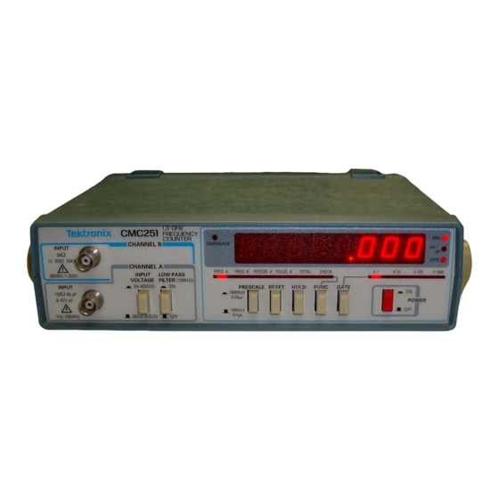
Page 13: Front Panel
Figure 2: Front Panel Controls, Connectors, and Indicators CAUTION. To avoid the risk of fire or possible damage to the CMC251, be sure that the equipment generating the signal is properly grounded before you make any connections to the inputs. - Page 14 LED. Each press of the button changes the degree of resolution to the next level. 10. FUNC Button. Determines the operating mode of the CMC251 Frequency Counter. 11. HOLD Button. Stops or locks the display when pressed in.
- Page 15 CHECK—The Check mode uses the internal time base as a signal source to make a general check of the operating system. The display will indicate a frequency of 10 MHz. CMC251 User Manual...
-
Page 16: Rear Panel
5 V. CAUTION. To avoid the risk of fire or possible damage to the CMC251, be sure that the equipment generating the signal is properly grounded before you make any connections to the inputs. 17. CHANNEL A INPUT. Use this connector to measure signals with a repetition rate from 1 Hz to 100 MHz. - Page 17 In Total mode, the TTL logic levels start (TTL high) and stop (TTL low) the display updates. This performs the same function as the HOLD button. In Pulse mode, the TTL logic levels select either negative (TTL low) or positive (TTL high) pulse width measurement. CMC251 User Manual...
- Page 18 Getting Started CMC251 User Manual...
-
Page 19: Reference
Reference This section describes typical setups of the CMC251 Frequency Counter for each of its measurement modes. Making Frequency Measurements Measuring frquencies with the CMC251 Frequency Counter is simple, although there are some items you need to consider before applying the signal to the inputs of the frequency counter. -
Page 20: Frequencies Below 100 Mhz
PRESCALE Button In Button In 3. Connect the signal to the CHANNEL A INPUT input connector. 4. Press the GATE button to select the desired display resolution. See Tables 4 and 5 for resolution versus gate settings. CMC251 User Manual... -
Page 21: Frequencies Between 80 Mhz And 1.3 Ghz
A Period measurement is the time in seconds for a signal to complete one entire cycle. This measurement is taken by averaging the signal events for a certain number of internal clock pulses. Therefore, the gate setting determines the resolution (or accuracy) of the reading. CMC251 User Manual... -
Page 22: Table 6: Period Measurements
Refer to Table 7 for the available resolutions. Table 7: Resolution For Period Measurements GATE Setting Number of Events averaged PRESCALE In PRESCALE Out 10 cycles 1 cycle 100 cycles 10 cycles X100 1000 cycles 100 cycles X1000 10000 cycles 1000 cycles CMC251 User Manual... -
Page 23: Making Pulse-Width Measurements
Therefore, the gate setting determines the resolution (or accuracy) of the reading. The CMC251 Frequency Counter normally measures the positive pulse width, but it can measure the negative pulse width using the external input connector on the rear panel. This method is discussed in Remote Control of Pulse-Width Measurements on page 14. -
Page 24: Remote Control Of Pulse-Width Measurements
To External Input connector (on rear panel) Signal source TTL Signal source CMC251 CHANNEL A INPUT Figure 4: Setup for Remote Control of Pulse-Width Measurements 1. Perform steps 1 through 5 of Making Pulse-Width Measurements on page 13. CMC251 User Manual... -
Page 25: Counting Events
Counting Events The CMC251 Frequency Counter can be used to count signal events. This feature can be controlled remotely with the use of TTL logic levels applied to the external input connector located on the rear panel. -
Page 26: Remote Control Of Total Mode
2. Connect a signal source that can apply TTL logic levels of low and high (0 V and +5 V) to the external input connector. CAUTION. To avoid damage to the CMC251 Frequency Counter, ensure that the maximum voltage into the rear panel input is no more than +5 V (TTL logic level). -
Page 27: Checking Instrument Operation
HOLD button) Checking Instrument Operation At any time, you can verify the accuracy of the CMC251 Frequency Counter by using the CHECK function. Press the FUNC button until CHECK is indicated by the lighted LED. The readout will display 10.000 MHz. - Page 28 Reference CMC251 User Manual...
-
Page 29: Appendix A: Specifications
30 MHz to 100 MHz 50 mV Impedance paralleled by 40 pF Attenuation 3 V to 42 V (HI) 50 mV to 5 V (LO) Maximum Input Voltage 42 V peak Filter –3 dB at 100 kHz CMC251 User Manual... - Page 30 Channel A: Selected GATE time plus 200 ms interval Channel B: Selected GATE time plus 640 ms interval Period Mode Selected cycles averaging plus 200 ms interval Pulse Mode Selected cycles averaging plus 200 ms interval Totalize Mode Continuous CMC251 User Manual...
- Page 31 Pulse Mode Range 0.25 s to 500 ms Frequency Range 1 Hz to 2 MHz Accuracy (1 count + time-base error + trigger error + 100 ns) Resolution 100 ps to 100 ns, switchable in four decade steps CMC251 User Manual...
- Page 32 90 VAC to 110 VAC 108 VAC to 132 VAC 198 VAC to 242 VAC 216 VAC to 250 VAC Environmental Operating Temperature +10 C to +40 C, 75% relative humidity Storage Temperature –10 C to +60 C, 80% relative humidity CMC251 User Manual...
-
Page 33: Table 11: Certifications And Compliances
Official Journal of the European Communities: Voltage Low Voltage Directive 73/23/EEC, amended by 93/68/EEC. HD401 S1 Safety Requirements for Electronic Measuring Aparatus. Table 12 lists the nonwarranted specifications of the CMC251 Frequency Counter. Table 12: Typical Characteristics Characteristic Measurement Dimensions... - Page 34 Appendix A: Specifications CMC251 User Manual...
-
Page 35: Appendix B: Maintenance
Appendix B: Maintenance This appendix provides information for the basic maintenance of the CMC251 Frequency Counter. Cleaning To clean the frequency counter, use a soft cloth dampened in a solution of mild detergent and water. Do not spray cleaner directly onto the instrument, since it may leak into the cabinet and cause damage. -
Page 36: Troubleshooting
No Display with Power On If the digital display is not lighted, but the POWER button is pushed in and the CMC251 Frequency Counter power cord is plugged into an outlet, do the following steps: 1. Check the line fuse. If the fuse is open, replace it. -
Page 37: Appendix C: Replaceable Parts
Appendix C: Replaceable Parts Replaceable parts may be ordered directly from your authorized Tektronix dealer. Standard Accessories The following items are shipped with the CMC251 Frequency Counter: Table 13: Standard Accessories Accessory Tektronix Part Number Fuse, 3AG, 0.3 A, 250 V, SB 159–0029–00... -
Page 38: Table 15: Accessory Power Cords
Table 15: Accessory Power Cords Tektronix Part Plug Configuration Normal Usage Number North America 161-0104-00 115 V Europe 161-0104-06 230 V United Kingdom 161-0104-07 230 V Australia 161-0104-05 230 V North America 161-0104-08 230 V Switzerland 161-0167-00 230 V CMC251 User Manual...
Need help?
Do you have a question about the CMC251 and is the answer not in the manual?
Questions and answers