
Related Manuals for WaterCare Evolve EV1-1044TW


Summary of Contents for WaterCare Evolve EV1-1044TW
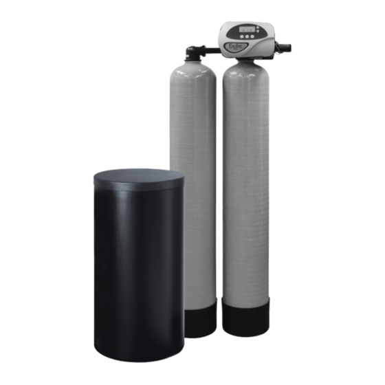
- Page 1 Evolve Series ® Twin Water Softeners and Conditioners For Models: • EV1-TW • EV2-TW • EVR-TW • EVRC-TW • EVRS-TW • EVRCS-TW...
-
Page 2: Table Of Contents
TABLE OF CONTENTS Preinstallation Instructions for Dealers . . . . . . . . . . . . . . . . . . . . . . . . . . . . . . . . . . 3 Bypass Valve . -
Page 3: Preinstallation Instructions For Dealers
PREINSTALLATION INSTRUCTIONS FOR DEALERS: The manufacturer has preset the water treatment unit’s sequence of cycles, cycle times, salt dose, exchange capacity and salt dose refill time . The dealer should read this page and guide the installer regarding hardness, day override, time of regeneration, service alarm and buzzer alarm settings before installation. -
Page 4: Bypass Valve
BYPASS VALVE: The bypass valve is typically used to isolate the control valve from the plumbing system’s water pressure in order to perform control valve repairs or maintenance . The 1” full flow bypass valve incorporates four positions, including a diagnostic position that allows a service technician to have pressure to test a system while providing untreated bypass water to the building . -
Page 5: Installation
INSTALLATION: GENERAL INSTALLATION & SERVICE WARNINGS The control valve, fittings and/or bypass are designed to accommodate minor plumbing misalignments . There is a small amount of “give” to properly connect the piping, but the water softener is not designed to support the weight of the plumbing . Do not use Vaseline, oils, other hydrocarbon lubricants or spray silicone anywhere . - Page 6 plumbing system first and then attach the nut, split ring and “O” Ring . Heat from soldering or solvent cements may damage the nut, split ring or “O” Ring . Solder joints should be cool and solvent cements should be set before installing the nut, split ring and “O”...
-
Page 7: Programming Procedures
PROGRAMMING PROCEDURES: 1. Set time of day: Time of day should only need to be set after extended power outages or when daylight saving time begins or ends . If an extended power outage occurs, the time of day will flash on and off indicating that the time should be reset . STEP 1 –... - Page 8 STEP 4 – IMMEDIATE REGENERATION: The manufacturer has set the regeneration to REGEN IMMEDIATE occur when zero gallons remain . When this occurs, the standby tank will switch ON ZERO into service and provide treated water while the tank requiring regeneration will start this process .
-
Page 9: Operating Displays And Instructions
OPERATING DISPLAYS AND INSTRUCTIONS: 1 . GENERAL OPERATION: When the system is operating, one of five displays may be shown and will alternate with the installing dealer’s name and phone number (if set) for future service . Pressing will alternate between the displays . next 1 . - Page 10 5 . POWER LOSS AND BATTERY REPLACEMENT: The transformer comes with a BATTERY REPLACEMENT 15 foot power cord and is designed for use with the control valve; the transformer should only be used in a dry location . In the event of a power outage, the control valve will remember all settings and time of day .
-
Page 11: Start-Up Instructions
START-UP INSTRUCTIONS: FLUSHING OF SYSTEM: To flush the system of any debris and air after installation is complete, please perform the following steps: 1 . Rotate bypass handles to the bypass mode (see Fig. 2 of page 4) . 2 . Turn on inlet water and check for leaks in the newly installed plumbing . 3 . -
Page 12: Troubleshooting Guide
TROUBLESHOOTING GUIDE: PROBLEM CAUSE CORRECTION A . No power at electric outlet A . Repair outlet or use working outlet B . Control valve power adapter not plugged into B . Plug power adapter into outlet or connect outlet or power cord end not connected to PC power cord end to PC board connection board connection 1. - Page 13 PROBLEM CAUSE CORRECTION A . Turn bypass handles to place bypass in A . Bypass valve in bypass position service position B . Meter is not connected to meter connection on B . Connect meter to three pin connection labeled PC board METER on PC board 7.
- Page 14 TROUBLESHOOTING GUIDE cont’d: PROBLEM CAUSE CORRECTION A . Injector is plugged A . Remove injector and clean or replace B . Faulty regenerant piston B . Replace regenerant piston C . Regenerant line connection leak C . Inspect regenerant line for air leak 12.
- Page 15 PROBLEM CAUSE CORRECTION A . Check motor connections then Press NEXT and REGEN buttons for 3 seconds to resynchronize A . Motor failure during a regeneration software with piston position or disconnect power supply from PC board for 5 seconds and then reconnect .
-
Page 16: Service Instructions For Transfer Assemblies
SERVICE INSTRUCTIONS: TRANSFER CAP ASSEMBLIES SERVICE INSTRUCTIONS 1 . The backplate of the control valve must first be removed to allow access to the Release locking tabs transfer cap assembly . from each side to remove back plate. 2 . Hold slight downward pressure on the top left corner of the backplate while using a thin flat screwdriver or knife blade to push in on the locking tabs . - Page 17 14 . With the outlet disc assembled to the shaft, the orientation of the shaft to inlet disc can be assured by installing the set with the through hole on the outlet disc at the 6 o’clock position . The easiest way to reassemble is to remove both disc drives and assemble the outlet side first .
-
Page 18: Replacement Parts
REPLACEMENT PARTS: FRONT COVER AND DRIVE ASSEMBLY Item No. Part No. Description Qty. CV3367-01-A Black cover CV3367- 01-WR-A Gray cover CV3107-1 Motor CV3106 -1 Drive bracket & spring clip CV3502WE Evolve PC board (used on chlorine generator models) CV4022WU Evolve PC board (standard) CV3110 Drive gear, 12 x 36 CV3109... - Page 19 REPLACEMENT PARTS: PISTON ASSEMBLY Item No. Part No. Description Qty. CV3005 1” spacer stack assembly CV3004 Drive cap assembly CV3135 O-ring 228 CV3011 1” piston assembly downflow CV3011-01 1” piston assembly upflow CV3174 Regenerant piston CV3368 Drive backplate...
- Page 20 REPLACEMENT PARTS: See pages 22-23...
- Page 21 REPLACEMENT PARTS: TWIN TRANSFER Item No. Part No. Description Qty. CV3470 Screw, BHC 1/4- 20 x 1 SS CV3724 Washer, flat SS 1/4 CV4005-01 T1 transfer cap assembly CV4029 O-ring 236 CV4015 T1 transfer spring CV4014 T1 transfer spring support CV4036 T1 rotor disk assembly CV3105...
- Page 22 REPLACEMENT PARTS: INJECTOR ASSEMBLIES Item No. Part No. Description Qty. CV3176 Injector cap CV3152 O-ring 135 CV3177-01 Injector screen CV3010-1Z Injector assembly plug A injector assembly, CV3010-1A black B injector assembly, CV3010-1B brown CV3010-1C C injector assembly, violet CV3010-1D D injector assembly, CV3010-1E E injector assembly, white...
- Page 23 REPLACEMENT PARTS: DRAIN LINE ASSEMBLY 3/4” Item No. Part No. Description Qty. CH4615 Elbow locking clip CPKP10TS8-BULK Optional insert, 5/8” tube CV3192 Optional nut, 3/4” drain elbow CV3158-02 Drain elbow, 3/4” NPT with O-ring CV3163 O-ring 019 CV3159-01 DLFC retainer assembly CV3162-007 0 .7 DLFC for 3/4”...
- Page 24 REPLACEMENT PARTS: WATER METER & METER PLUG Item No. Part No. Description Qty. CV3151 Nut, 1” QC CV3003 Meter assembly, includes items 3 & 4 CV3118-01 Turbine assembly CV3105 O-ring 215 CV3003-01 Meter plug assembly...
- Page 25 REPLACEMENT PARTS: BRINE TANK ASSEMBLY Item No. Part No. Description Qty. CG2191-92 Brine tank cover, injection molded Evolve CG2180 Brine tank cover, standard CH1095-01 Optional 18” diameter salt grid CH1080 Optional 24” diameter salt grid CG21833CB1C00 18” x 33” brine tank, black CG21840CB1C00 18”...
- Page 26 REPLACEMENT PARTS: IN/OUT HEAD (FOR TANK B) Item No. Part No. Description Qty. CD1400 1191 In/Out head (includes O-rings) CV3180 O-ring 337 CV3105 O-ring 215 SERVICE WRENCH - CV3193-02 Although no tools are necessary to assemble or disassemble the valve, the Service Wrench, (shown in various positions on the valve) is available to aid in assembly or disassembly .
- Page 27 REPLACEMENT PARTS: BYPASS VALVE Item No. Part No. Description Qty. CV3151 Nut, 1” quick connect CV3150 Split ring CV3105 O-ring 215 CV3145 Bypass rotor, 1” CV3146 Bypass cap CV3147 Bypass handle CV3148 Bypass rotor seal retainer CV3152 O-ring 135 CV3155 O-ring 112 CV3156 O-ring 214...
- Page 28 INSTALLATION FITTING ASSEMBLIES: Fitting Installation Instructions • Installation fittings are designed to accommodate minor plumbing misalignments, but are not designed to support the weight of a system or the plumbing . • Slide nut on first, then the split ring and O-ring . •...
- Page 29 INSTALLATION FITTING ASSEMBLIES: 1” PVC MALE NPT ELBOW 3/4” & 1” PVC SOLVENT ELBOW Item Item Part No. Description Qty. Part No. Description Qty. CV3007 1” PVC male NPT elbow assembly CV3007- 01 3/4” & 1” PVC solvent elbow assembly CV3151 Nut, 1”...
- Page 30 INSTALLATION FITTING ASSEMBLIES: 1-1/4” & 1-1/2” BRASS SWEAT 1-1/4” & 1-1/2” PVC SOLVENT Item Item Part No. Description Qty. Part No. Description Qty. CV3007-09 1-1/4 & 1-1/2” brass sweat assembly CV3007-07 1-1/4” & 1-1/2” PVC solvent assembly CV3151 Nut, 1” quick connect CV3151 Nut, 1”...
-
Page 31: Specifications
EVOLVE SERIES TWIN CONDITIONER SPECIFICATIONS: MODEL EV1-1044TW EV1-1054TW EV1-1354TW EV2-1044TW EV2-1054TW EV2-1354TW Capacity: Maximum 11,800 @ 12 .4 22,600 @ 15 .9 36,900 @ 21 .2 20,300 @ 12 .4 34,800@ 15 .9 60,300 @ 26 .5 (Grains/Lbs . NaCI) Medium 11,400 @ 9 .3 20,700 @ 12 .4... - Page 32 EVOLVE SERIES TWIN SOFTENER SPECIFICATIONS: MODEL EVR(S) -844TW EVR(S)-1044TW EVR(S) -1054TW EVR(S) -1354TW EVR(S)-1465TW EVR(S)-1665TW Maximum 25,600 @ 9 .0 32,000 @ 15 .0 48,800 @ 21 .0 72,800 @ 24 .0 90,000 @ 45 .0 120,000 @ 60 .0 Capacity: Medium 21,600 @ 6 .0...
-
Page 33: Warranty
Evolve Series Water Conditioner Limited Warranty ® Congratulations. You have purchased one of the finest water treatment systems available. In the unlikely event of a problem due to defects in material and workmanship, Water-Right proudly warrants our Evolve Series water ®... -
Page 34: Quick Reference Guide
TIME OF DAY 2:40 QUICK REFERENCE GUIDE: FLOW RATE GENERAL OPERATION MANUAL REGENERATION NOTE: For softeners, if brine tank does When the system is operating, one of six displays will be shown: REGEN TODAY and TIME OF DAY will flash alternately if a regeneration 1 . -
Page 35: Hardness
ADJUST HARDNESS, DAYS BETWEEN REGENERATION, TIME OF REGENERATION AND ALARM BUZZER For initial set-up or to make adjustments, please complete the following steps . 1 . Accessed by pressing and + button simultaneously next 2 . Adjust hardness using + and — buttons SERVICE ALARM 3 . - Page 36 Manufactured exclusively for Evolve Series Dealers at: 1900 Prospect Court • Appleton, WI 54914 Phone: 920-739-9401 • Fax: 920-739-9406 © 2014 Evolve Series All rights reserved. LIT-EV TW MAN 2/17...
Need help?
Do you have a question about the Evolve EV1-1044TW and is the answer not in the manual?
Questions and answers